
收到板卡,开始站在一个新手的角度,开始探索之旅。
首先,下载资料
下载资料的网址是http://www.eepw.com.cn/event/action/STM32_L053/index.html
STM32 NUCLEO板用户手册(UM1724)
翻开目录,找到Getting Started
Getting started
Follow the sequence below to configure the STM32 Nucleo board and launch the demo
software:
1.Check the jumper position on the board, JP1 off, JP5 (PWR) on U5V, JP6 on (IDD),
CN2 on (NUCLEO) selected.
2. For correct identification of all device interfaces from the host PC, install the Nucleo
USB driver available on www.st.com/stm32nucleo, prior to connecting the board
3. Connect the STM32 Nucleo board to a PC with a USB cable !(R)type A to mini-B!¡¥ throug
USB connector CN1 to power the board. The red LED LD3 (PWR) and LD1 (COM)
should light up. LD1 (COM) and green LED LD2 should blink.
4. Press button B1 (left button).
5. Observe how the blinking of the green LED LD2 changes according to clicks on button
B1.
6. The demo software and several software examples on how use the STM32 Nucleo
board features are available on www.st.com/stm32nucleo.
7. Develop the application using the available examples.
开始
按照下面的顺序配置STM32Nucleo板和运行演示
软件:
1。检查跳线位置在板上,JP1(处于OFF状态),JP5(PWR)在U5V端,JP6(在IDD端),
CN2(NUCLEO端)。
2。为正确识别所有设备接口从主机电脑,安装而言,连接之前,
USB驱动程序可以在www.st.com/stm32nucleo,下载
3所示。STM32其核心板连接到PC机的USB电缆!(R)型mini-B !¡¥沿着
USB连接器CN1董事会。红色LED LD3(压水式反应堆)和LD1(COM)
应该点亮。LD1(COM)和绿色LED LD2应该眨眼。
4所示。按钮B1(左按钮)。
5。观察闪烁的绿色LED LD2的变化根据点击按钮
B1。
6。演示软件和几个例子如何使用STM32而言
董事会特征可在www.st.com/stm32nucleo上。
7所示。使用可用的开发应用程序的例子。
JP1的配置
JP1 is configured according to the maximum current consumption of the board when
powered by USB (U5V). JP1 jumper can be set in case the board is powered by USB and
maximum current consumption on U5V doesn!¡¥t exceed 100mA (including an eventual
extension board or Arduino Shield). In such condition USB enumeration will always succeed
since no more than 100mA is requested to the PC. Possible configurations of JP1 are
summarized in
Table 5.
Table 5. JP1 configuration table
Jumper state Power supply Allowed current
JP1 jumper OFF 300 mA max
USB power through CN1
JP1 jumper ON 100 mA max
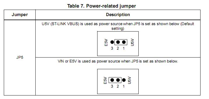
JP5的配置
When the board is power supplied by USB (U5V) a jumper must be connected between pin
1 and pin 2 of JP5 as shown in 板卡由USB供电/或者外部供电的跳针配置。
Table 7.
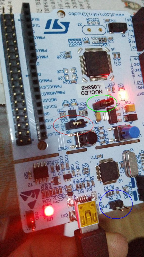
红圈处JP5,下方USB接口的右边 蓝圈处JP1,绿圈处JP6
JP6配置:
JP6 (IDD)
Jumper JP6, labeled IDD, is used to measure the STM32 microcontroller consumption by
removing the jumper and by connecting an ammeter. Jumper ON: STM32 microcontroller is powered (default). Jumper OFF: an ammeter must be connected to measure the STM32 microcontroller
current. If there is no ammeter, STM32 microcontroller is not powered.OSC clock
ON的时候默认,
OFF的时候,需要外接一个电流表。
也就是说,这里可以测量板卡的电流?
 STM32
STM32 MCU
MCU 通讯及无线技术
 物联网技术
物联网技术 电子DIY
电子DIY 板卡试用
板卡试用 基础知识
基础知识 软件与操作系统
 我爱生活
我爱生活 小e食堂
小e食堂