
 。 我尽量把屏幕和板一起拍进去了,在我的电脑上是超清视频是可以看清屏幕的,上传到优酷,缩水变成标清就不看太清楚了,所以就截了个图。还没有想到好点的方法,如果两个人,有一个人帮拍可能会好点。回头好好看看其他人怎么弄得。
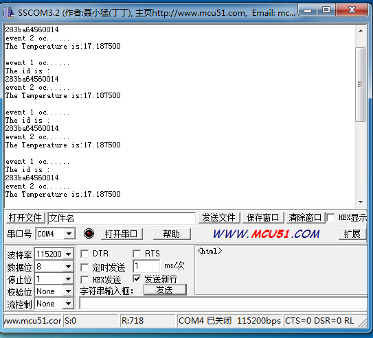
 系统滴答&18B20
系统时钟配置为48MHZ,由滴答控制,300ms输出一次18B20的ID,500ms输出一次温度。
#include "stm32f10x.h"
#include "stm32_eval.h"
#include <stdio.h>
#define Set_B20()    GPIO_SetBits(GPIOC, GPIO_Pin_12)
#define Reset_B20()  GPIO_ResetBits(GPIOC, GPIO_Pin_12)
#define Read_B20()   GPIO_ReadInputDataBit(GPIOC,GPIO_Pin_12)
volatile int flag;
unsigned char Error_Flag=0;
unsigned char zf=0;
unsigned char ID[8];
void delay_us(u32 n)
{
    u8 j;
    while(n--)
    for(j=0;j<10;j++);
}
void  delay_ms(u32 n)
{
  while(n--)
    delay_us(1000);
}

void SysTick_Configuration(void)
{
  /* Setup SysTick Timer for 1 msec interrupts  */
  if (SysTick_Config(48000))                //SysTick配置 48000/48MHZ=1ms 滴答一次
  {
    /* Capture error */
    while (1);
  }
 /* Configure the SysTick handler priority */
  NVIC_SetPriority(SysTick_IRQn, 0x0);                       //SysTick中断优先级
}

GPIO_InitTypeDef   GPIO_InitStructure;
USART_InitTypeDef USART_InitStructure;
USART_ClockInitTypeDef USART_ClockInitStructure;
#define RCC_PLLSource_HSE_Div1           ((uint32_t)0x00010000)

void RCC_Configuration(void)
{
  RCC_DeInit();

  RCC_HSICmd(ENABLE);
  while(RCC_GetFlagStatus(RCC_FLAG_HSIRDY) == RESET);

  RCC_SYSCLKConfig(RCC_SYSCLKSource_HSI);

  RCC_HSEConfig(RCC_HSE_OFF);
  RCC_LSEConfig(RCC_LSE_OFF);
  RCC_PLLConfig(RCC_PLLSource_HSI_Div2,RCC_PLLMul_6); // 6*8Mhz= 48MHz
  RCC_PLLCmd(ENABLE);
  while(RCC_GetFlagStatus(RCC_FLAG_PLLRDY) == RESET);
  RCC_ADCCLKConfig(RCC_PCLK2_Div4);
  RCC_PCLK2Config(RCC_HCLK_Div1);
  RCC_PCLK1Config(RCC_HCLK_Div2);
  RCC_HCLKConfig(RCC_SYSCLK_Div1);
  RCC_SYSCLKConfig(RCC_SYSCLKSource_PLLCLK);
  while(RCC_GetSYSCLKSource() != 0x08)
//  SystemInit();
    RCC_APB2PeriphClockCmd(RCC_APB2Periph_GPIOD|RCC_APB2Periph_AFIO, ENABLE);
 GPIO_PinRemapConfig(GPIO_Remap_SWJ_JTAGDisable,ENABLE);//disable JTAG
RCC_APB2PeriphClockCmd(RCC_APB2Periph_GPIOD|RCC_APB2Periph_AFIO, ENABLE);
 GPIO_PinRemapConfig(GPIO_Remap_SWJ_JTAGDisable,ENABLE);//disable JTAG
  GPIO_InitStructure.GPIO_Pin = GPIO_Pin_2;
  GPIO_InitStructure.GPIO_Speed = GPIO_Speed_50MHz;
  GPIO_InitStructure.GPIO_Mode = GPIO_Mode_Out_PP;
  GPIO_Init(GPIOD, &GPIO_InitStructure);
    GPIO_ResetBits(GPIOD,GPIO_Pin_2);
    RCC_APB2PeriphClockCmd(RCC_APB2Periph_GPIOC|RCC_APB2Periph_AFIO, ENABLE);
 GPIO_PinRemapConfig(GPIO_Remap_SWJ_JTAGDisable,ENABLE);//disable JTAG
  GPIO_InitStructure.GPIO_Pin = GPIO_Pin_0|GPIO_Pin_1|GPIO_Pin_2|GPIO_Pin_3|GPIO_Pin_4|GPIO_Pin_5|GPIO_Pin_6|GPIO_Pin_7;
  GPIO_InitStructure.GPIO_Speed = GPIO_Speed_50MHz;
  GPIO_InitStructure.GPIO_Mode = GPIO_Mode_Out_PP;
  GPIO_Init(GPIOC, &GPIO_InitStructure);
    GPIO_SetBits(GPIOC,GPIO_Pin_0|GPIO_Pin_1|GPIO_Pin_2|GPIO_Pin_3|GPIO_Pin_4|GPIO_Pin_5|GPIO_Pin_6|GPIO_Pin_7);
      RCC_APB1PeriphClockCmd(RCC_APB1Periph_TIM2, ENABLE);
}

void USART_int(long BaudRate)
{
    RCC_APB2PeriphClockCmd(RCC_APB2Periph_GPIOA|RCC_APB2Periph_USART1,ENABLE);
       GPIO_InitStructure.GPIO_Pin = GPIO_Pin_9;
    GPIO_InitStructure.GPIO_Speed = GPIO_Speed_50MHz;
    GPIO_InitStructure.GPIO_Mode = GPIO_Mode_AF_PP;
    GPIO_Init(GPIOA, &GPIO_InitStructure);
    /* PA10 USART1_Rx  */
    GPIO_InitStructure.GPIO_Pin = GPIO_Pin_10;
    GPIO_InitStructure.GPIO_Mode = GPIO_Mode_IN_FLOATING;
    GPIO_Init(GPIOA, &GPIO_InitStructure);
  /* USARTx configured as follow:
        - BaudRate = 115200 baud
        - Word Length = 8 Bits
        - One Stop Bit
        - No parity
        - Hardware flow control disabled (RTS and CTS signals)
        - Receive and transmit enabled
  */
  USART_InitStructure.USART_BaudRate = BaudRate;//??????
  USART_InitStructure.USART_WordLength = USART_WordLength_8b;//???????8bit
  USART_InitStructure.USART_StopBits = USART_StopBits_1;//????1
  USART_InitStructure.USART_Parity = USART_Parity_No;//????
  USART_InitStructure.USART_HardwareFlowControl = USART_HardwareFlowControl_None;//??????none
  USART_InitStructure.USART_Mode = USART_Mode_Rx | USART_Mode_Tx;//??????????
    USART_ClockInitStructure.USART_Clock = USART_Clock_Disable;
    USART_ClockInitStructure.USART_CPOL = USART_CPOL_Low;
    USART_ClockInitStructure.USART_CPHA = USART_CPHA_2Edge;
    USART_ClockInitStructure.USART_LastBit = USART_LastBit_Disable;
    USART_ClockInit(USART1, &USART_ClockInitStructure);
  USART_Init(USART1, &USART_InitStructure);
  USART_Cmd(USART1, ENABLE);
    USART_ITConfig(USART1, USART_IT_RXNE, ENABLE);
 USART_Cmd(USART1, ENABLE);
}

void delay_18b20(u32 nus)
{
    u16 i;
    while(nus--)
        for(i=12;i>0;i--);
}
  void Init18B20(void)//18B20初始化
{
   u8 b=0;
   u8 count =0;
    RCC_APB2PeriphClockCmd(RCC_APB2Periph_GPIOC, ENABLE); //GPIOC的复用时钟使能
  GPIO_InitStructure.GPIO_Pin = GPIO_Pin_12;//选择PC12
  GPIO_InitStructure.GPIO_Mode = GPIO_Mode_Out_OD;//开漏输出
  GPIO_Init(GPIOC, &GPIO_InitStructure);//GPIOC初始化
   Set_B20() ;
    /*复位时需要至少480us的低电平*/
   delay_18b20(1);
   Reset_B20();
   delay_18b20(480);
    /* 探测到上升沿后等待15~60us后18B20发出存在脉冲 */
   Set_B20();
   delay_18b20(480);

    count=0;
    b=Read_B20();//读取18B20的一个字节 赋值给aa

    /*   校验读取值,错误次数大于99才报错 */
    while(!b && count<100)
   {
    b=Read_B20();
        count++;
   }
   if(count>=99)
        Error_Flag=1;
    else
        Error_Flag=0;
}

unsigned char Read18B20(void)//读取18B20的一个字节
{
    unsigned char i=0;
    unsigned char date=0;
    u8 tempp;
   for(i=8;i>0;i--)//按位读取,读取一个字需要循环8次
   {
        Reset_B20();//拉低电平
        date>>=1;//date右移一位
        delay_18b20(1);
        Set_B20(); //置高电平
    delay_18b20(1);
        tempp=Read_B20();//读取温度值
        if(tempp)//若读取到的值非0
    {date|=0x80;} //将date的最高位置1
        delay_18b20(60);
    }
    return(date);
}
void Write18B20(unsigned char date)//写入
{
    unsigned char i=0;

    for (i=8; i>0; i--)
    {
        Reset_B20(); //置低电平
        delay_18b20(1);
        if(date & 0x01)     //如果date最低位为1
        {
            Set_B20();//置高电平
        }
        else//如果date最低位为0
        {
            Reset_B20();}//置低电平
            delay_18b20(60);
            date>>=1;     //date右移一位
            Set_B20();//置高电平
            delay_18b20(1);
    }
    delay_18b20(15);
}

 float Read_T()//读取温度值
{
    unsigned char TUp,TDown;
    unsigned char fTemp;
    u8 TT=0;
    float Temp = 0;
    Init18B20();//1820初始化
    Write18B20(0xcc); //不提供64位ROM编码使用存储器
    Write18B20(0x44); //启动一次温度转换
    Init18B20();//1820初始化
    Write18B20(0xcc); //不提供64位ROM编码使用存储器
    Write18B20(0xbe);   //从字节0开始读取暂存器内容
    /*两次读取温度*/
    TDown = Read18B20();
    TUp = Read18B20();

    if(TUp>0x7f)    //  如果TUp的值大于最大值(11111111)bin
    {
        TDown=~TDown;  //TDown取反
        TUp=~TUp+1; //TUp取反加一
        TUp/=8; //TUp除以8
        zf=1;    //zf标志位置1
    }
    else
        zf=0;
    fTemp=TDown&0x0f;//TDown保留后四位,赋值给fTemp
    TUp<<=4;//TUp左移四位,舍去高四位
    TDown>>=4;//TDown右移四位,舍去低四位
    TT=TUp|TDown;//TUp与TDown合并 赋值给TT
    Temp=TT+(float)fTemp/16;
    return(Temp);
}

int main(void)
{
    int i;
    RCC_Configuration();
    USART_int(115200);
    Init18B20();//初始化18B20
    SysTick_Configuration();//系统滴答时钟配置

    printf(" config done...\r\n");
    Write18B20(0x33);//此命令获取18B20的ID
    for(i=0;i<8;i++)//用一个8位的数组保存id值
    {
        ID[i]=Read18B20();
    }
    delay_ms(1000);
    while(1)
    {}
}

void SysTick_Handler(void)
{
  int i;
    flag++;
    if(flag==300)//每300ms输出一次id
    {
        printf("\r\nevent 1 oc......\r\n");
        printf("The id is :\r\n");
        for(i=0;i<8;i++)
        {
            printf("%x",ID[i]);
        }
    }
    else if(flag==500)//每500ms输出一次温度
    {
        printf("\r\nevent 2 oc......\r\n");
        printf("The Temperature is:%f\r\n",Read_T());
        flag = 0;
    }
}
#ifdef  USE_FULL_ASSERT

/**
  * @brief  Reports the name of the source file and the source line number
  *         where the assert_param error has occurred.
  * @param  file: pointer to the source file name
  * @param  line: assert_param error line source number
  * @retval None
  */
void assert_failed(uint8_t* file, uint32_t line)
{
  /* User can add his own implementation to report the file name and line number,
     ex: printf("Wrong parameters value: file %s on line %d\r\n", file, line) */

  /* Infinite loop */
  while (1)
  {
  }
}

#endif

#ifdef __GNUC__
  /* With GCC/RAISONANCE, small printf (option LD Linker->Libraries->Small printf
     set to 'Yes') calls __io_putchar() */
  #define PUTCHAR_PROTOTYPE int __io_putchar(int ch)
#else
  #define PUTCHAR_PROTOTYPE int fputc(int ch, FILE *f)
#endif /* __GNUC__ */


/**
  * @brief  Retargets the C library printf function to the USART.
  * @param  None
  * @retval None
  */
PUTCHAR_PROTOTYPE
{
  /* Place your implementation of fputc here */
  /* e.g. write a character to the USART */
  USART_SendData(EVAL_COM1, (uint8_t) ch);

  /* Loop until the end of transmission */
  while (USART_GetFlagStatus(EVAL_COM1, USART_FLAG_TC) == RESET)
  {}

  return ch;
}

#ifdef  USE_FULL_ASSERT

/**
  * @brief  Reports the name of the source file and the source line number
  *         where the assert_param error has occurred.
  * @param  file: pointer to the source file name
  * @param  line: assert_param error line source number
  * @retval None
  */
void assert_failed(uint8_t* file, uint32_t line)
{
  /* User can add his own implementation to report the file name and line number,
     ex: printf("Wrong parameters value: file %s on line %d\r\n", file, line) */

  /* Infinite loop */
  while (1)
  {
  }
}

#endif
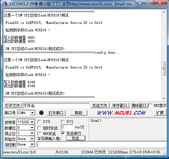
SPI从ADC中获取数值的代码作业
串口调试助手截图
/* Includes ------------------------------------------------------------------*/
#include "stm32f10x.h"
#include "stm32_eval.h"
#include
#include "spi_flash.h"
#define VREF 3.3
#define TxBufferSize1   (countof(TxBuffer1) - 1)
#define RxBufferSize1   (countof(TxBuffer1) - 1)
#define countof(a)      (sizeof(a) / sizeof(*(a)))
#define  BufferSize (countof(Tx_Buffer)-1)
typedef enum { FAILED = 0, PASSED = !FAILED} TestStatus;
#define  FLASH_WriteAddress     0x00000
#define  FLASH_ReadAddress      FLASH_WriteAddress
#define  FLASH_SectorToErase    FLASH_WriteAddress
#define  sFLASH_ID              0xEF3015     //W25X16
//#define  sFLASH_ID              0xEF4015   //W25Q16
#define buff_size  16;
char rx_buff[],rx_buff_count=0;
uint8_t Tx_Buffer[4096] ;
uint8_t Rx_Buffer[BufferSize];
__IO uint32_t DeviceID = 0;
__IO uint32_t FlashID = 0;
__IO TestStatus TransferStatus1 = FAILED;

 void delay_us(u32 n)
{
    u8 j;
    while(n--)
    for(j=0;j<10;j++);
}

void  delay_ms(u32 n)
{
    while(n--)
    delay_us(1000);
}

void Delay(__IO uint32_t nCount);
TestStatus Buffercmp(uint8_t* pBuffer1, uint8_t* pBuffer2, uint16_t BufferLength);

/** @addtogroup STM32F10x_StdPeriph_Examples
  * @{
  */

/** @addtogroup EXTI_Config
  * @{
  */

/* Private typedef -----------------------------------------------------------*/
/* Private define ------------------------------------------------------------*/
/* Private macro -------------------------------------------------------------*/
/* Private variables ---------------------------------------------------------*/
GPIO_InitTypeDef   GPIO_InitStructure;
USART_InitTypeDef USART_InitStructure;
USART_ClockInitTypeDef USART_ClockInitStructure;

char *int_to_string(int number,char *strnum)//整形数据转换为字符型
{
int j=0,i=0,n=0;
char temp;
while(number>0)
{
*(strnum+j)=number%10+48;
j++;
number=number/10;
n++;
}


for(i=0;iLibraries->Small printf
     set to 'Yes') calls __io_putchar() */
  #define PUTCHAR_PROTOTYPE int __io_putchar(int ch)
#else
  #define PUTCHAR_PROTOTYPE int fputc(int ch, FILE *f)
#endif /* __GNUC__ */


/**
  * @brief  Retargets the C library printf function to the USART.
  * @param  None
  * @retval None
  */
PUTCHAR_PROTOTYPE
{
  /* Place your implementation of fputc here */
  /* e.g. write a character to the USART */
  USART_SendData(EVAL_COM1, (uint8_t) ch);

  /* Loop until the end of transmission */
  while (USART_GetFlagStatus(EVAL_COM1, USART_FLAG_TC) == RESET)
  {}

  return ch;
}

#ifdef  USE_FULL_ASSERT

/**
  * @brief  Reports the name of the source file and the source line number
  *         where the assert_param error has occurred.
  * @param  file: pointer to the source file name
  * @param  line: assert_param error line source number
  * @retval None
  */
void assert_failed(uint8_t* file, uint32_t line)
{
  /* User can add his own implementation to report the file name and line number,
     ex: printf("Wrong parameters value: file %s on line %d\r\n", file, line) */

  /* Infinite loop */
  while (1)
  {
  }
}

#endif
关于焊电路板总结帖
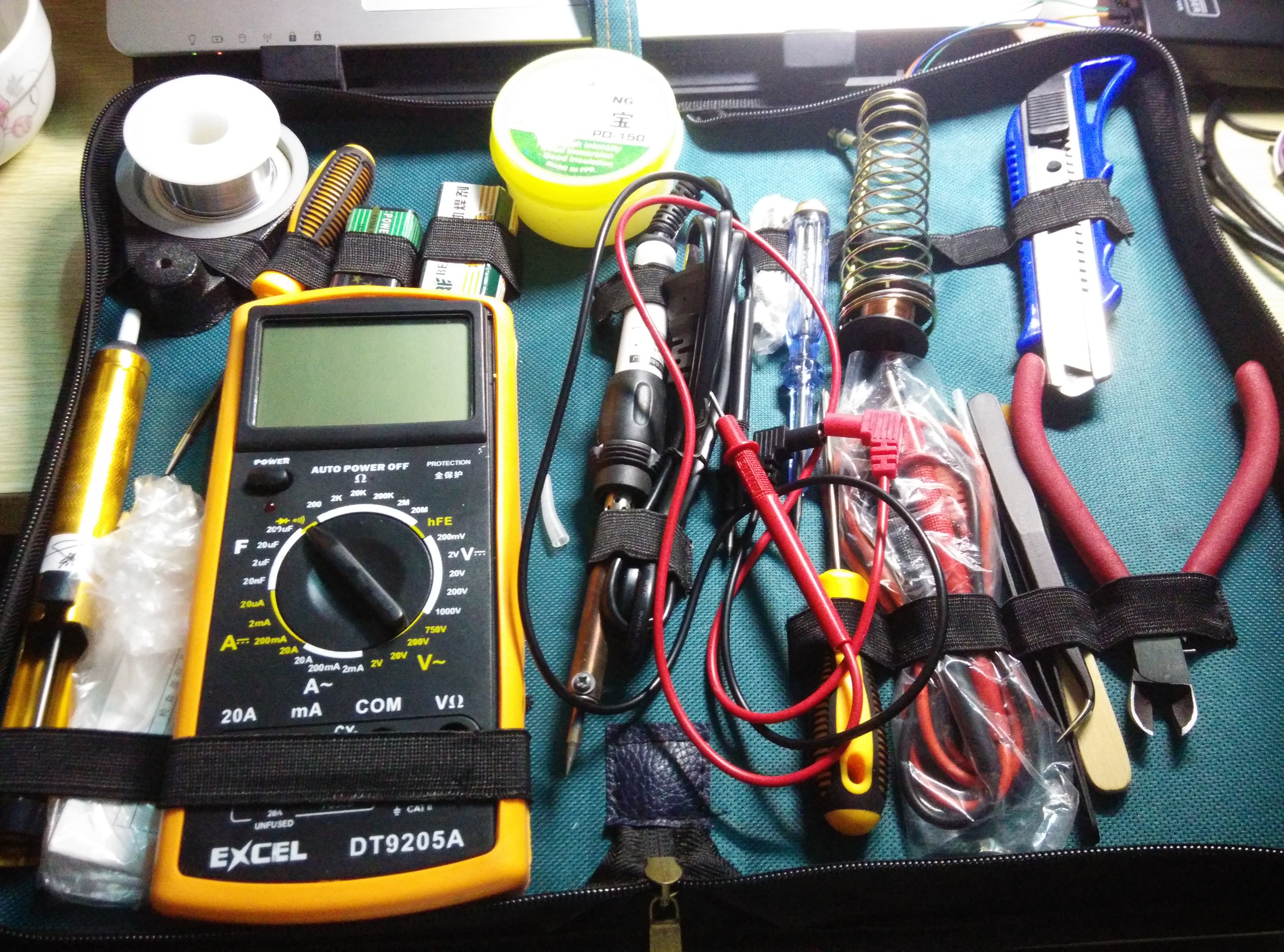
焊接板只要做好以下几点其实是很容易的。
1.做好焊接部件的先后顺序,小的部件先焊,大的后面焊接。就是把握好焊接顺序就好了。
2.还有就是掌握好焊接的小技巧,利用一些小的技巧就可以了。
下面说说焊接要准备的一些工具如图:
接下来就是焊接了。经过焊接课程其实大多数的焊接技巧都掌握好了。这里我就不多说了。
说说大多数同学遇到的问题。也是难题那就是焊接芯片了。因为我们的芯片管脚很细,因此加大了焊接的难度。其实焊好后。
掌握方法也是不难的。下面我说说焊接的方法与技巧。
1.首先焊的核心板芯片,把管脚对齐,用透明胶布固定(检查管脚是否对其有个技巧,就是把板放到台灯下可以更好地观察到);
2.在芯片管脚上再涂上焊宝(我推荐大家最好使用焊宝,因为焊宝币松香更好用一点),这样就可以固定好芯片方便焊接了;
3.就是焊接了,焊这颗芯片千万不要加焊锡,并且要处理干净电烙铁,不然会不小心把芯片管脚焊短路了。焊接等烙铁达到温度后,
就慢慢加热芯片管脚就好了,这样芯片就焊好了!
涂焊宝
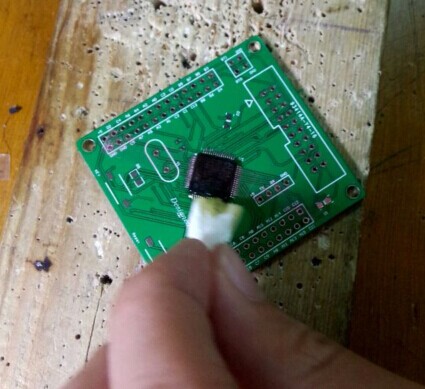
焊好芯片其他的贴片就很简单啦
可以先在焊盘上加一点焊锡,要有足够的焊锡才能把这些小贴片焊稳了

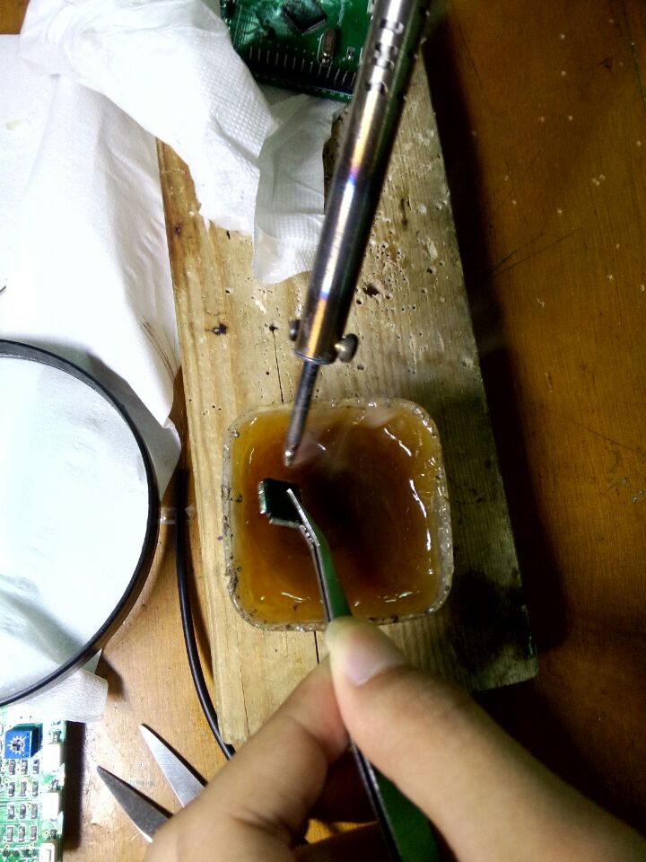
下面介绍一种针对芯片管脚被焊锡粘住后的解决方案
这是非常麻烦的一件事,很多同学不知道怎么处理,很难弄干净芯片的管脚。
用对方法其实就简单很多啦,方法就是使用焊宝或松香清洗就好了。
把被焊锡粘住的芯片放到焊宝或松香盒里。使用电烙铁加热。这样焊锡就好沉入焊宝盒的底部跟芯片管脚分开啦。
如图
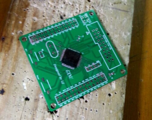
下面是我的焊好的板的效果展示:
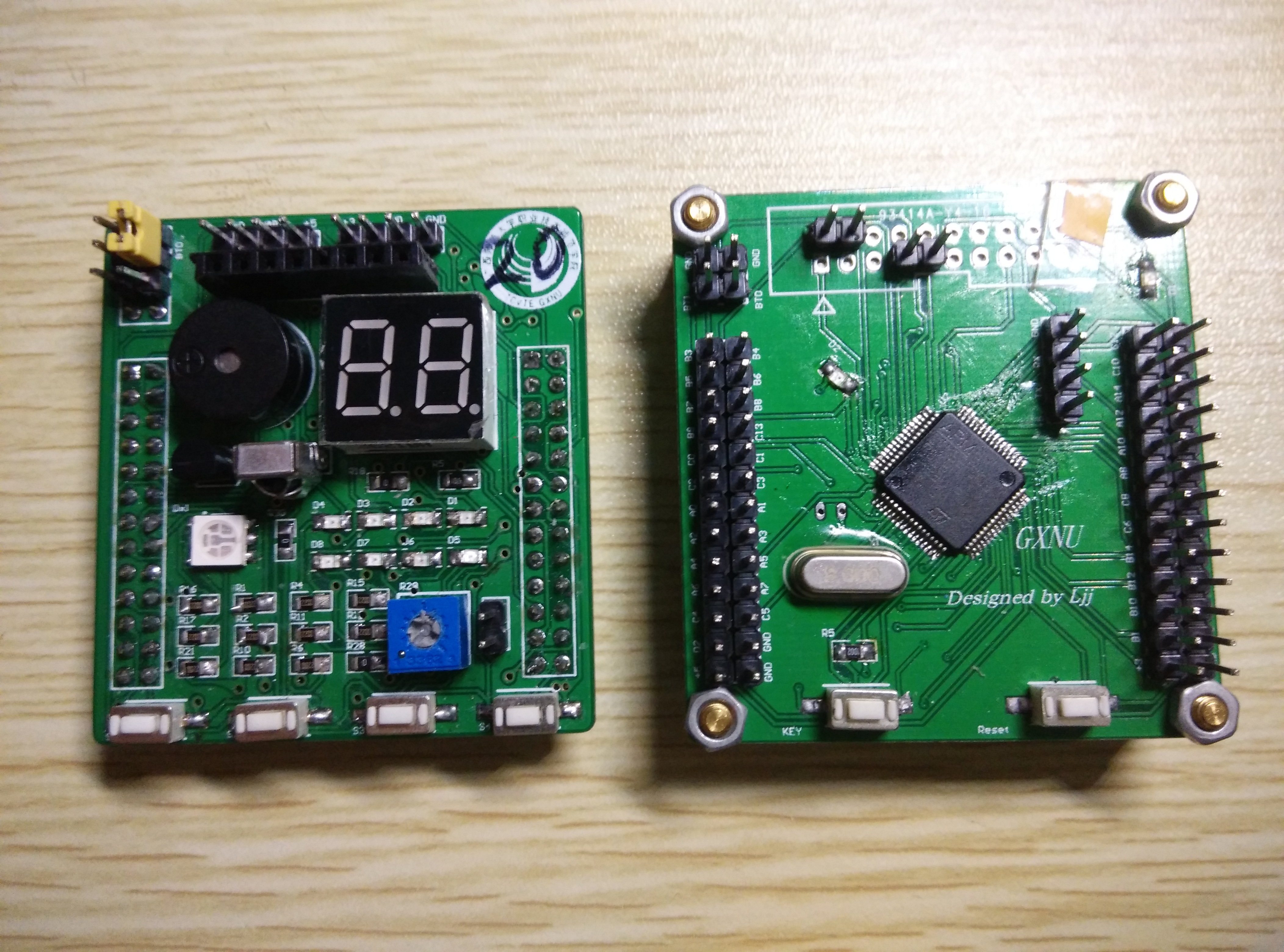
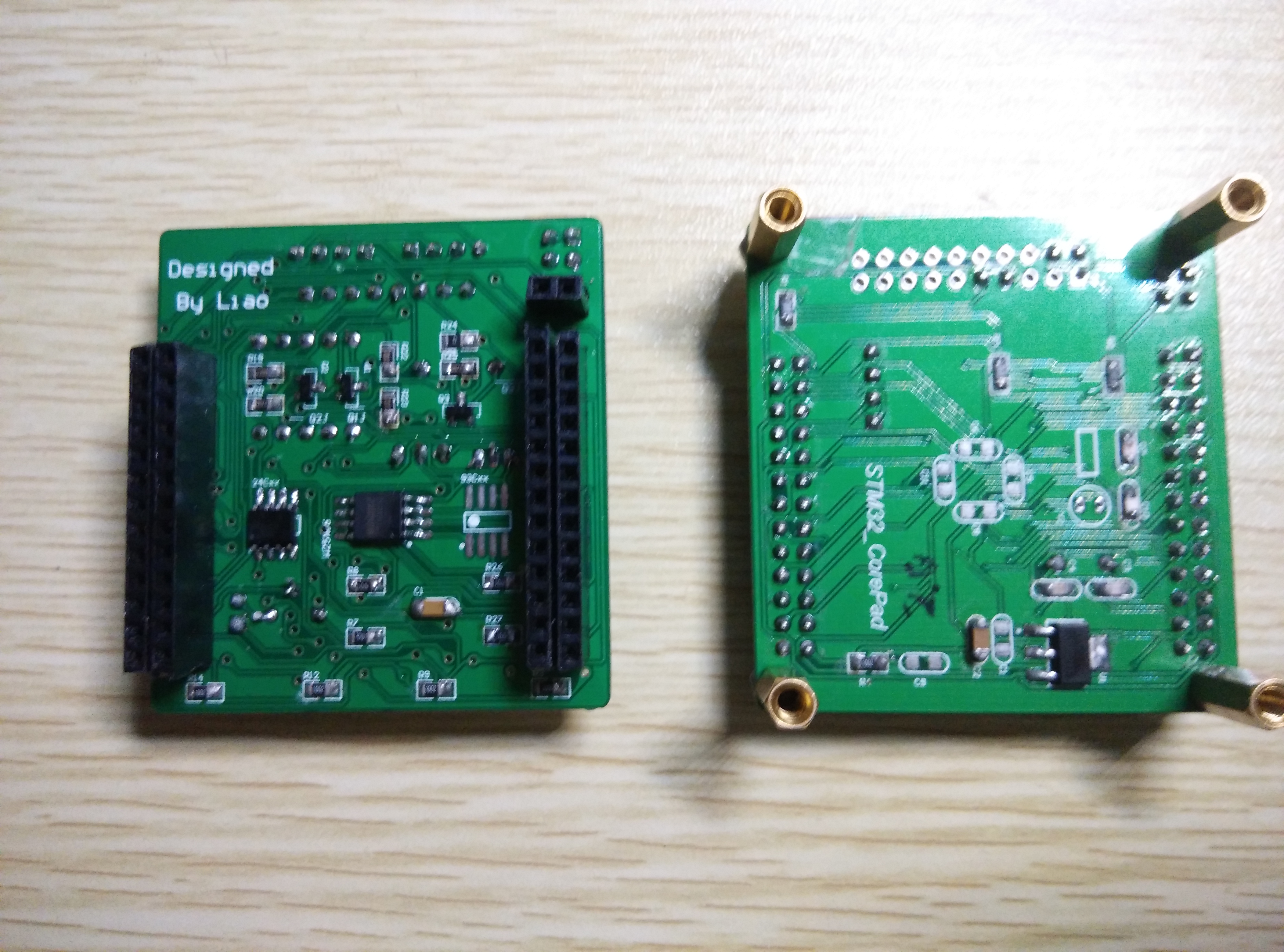
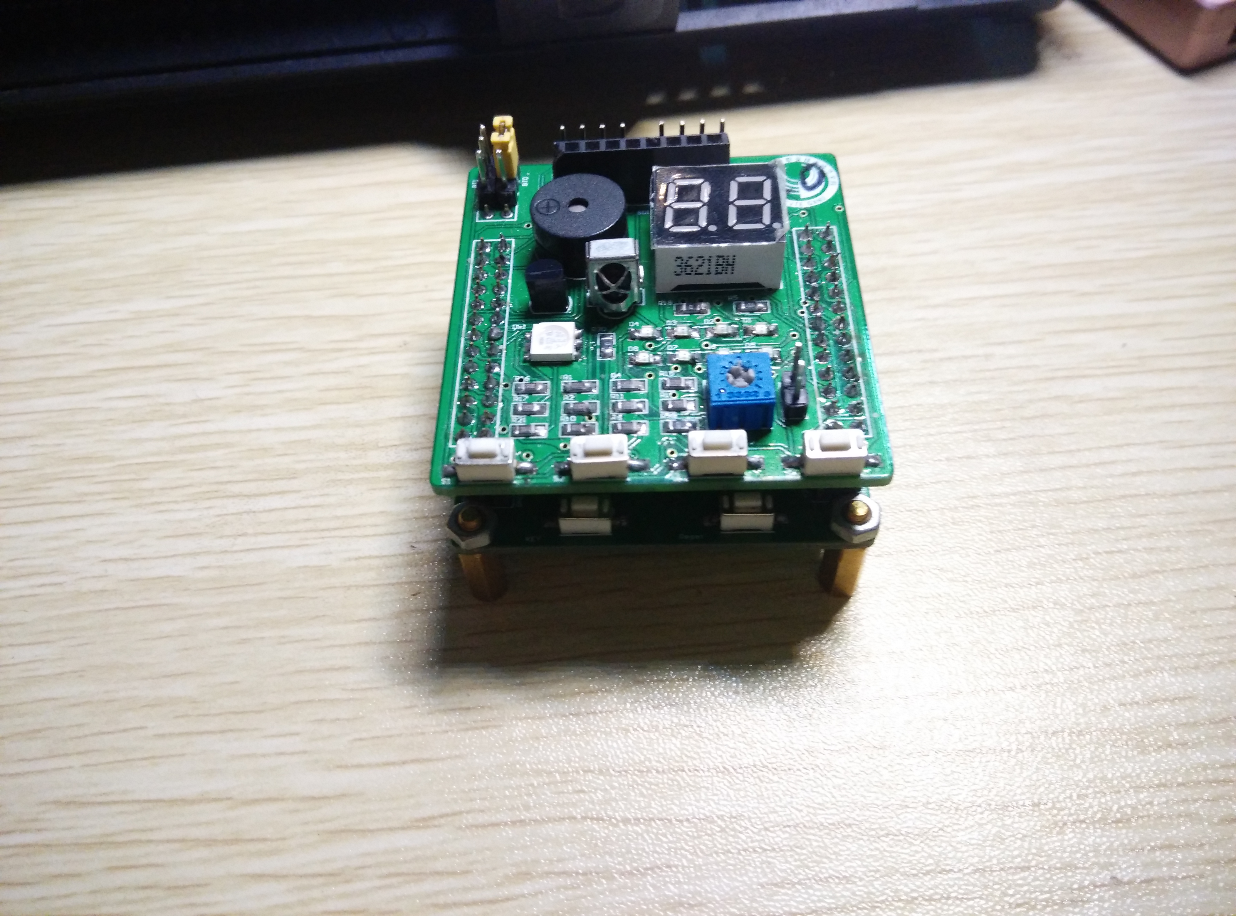
使用时候的线的连接
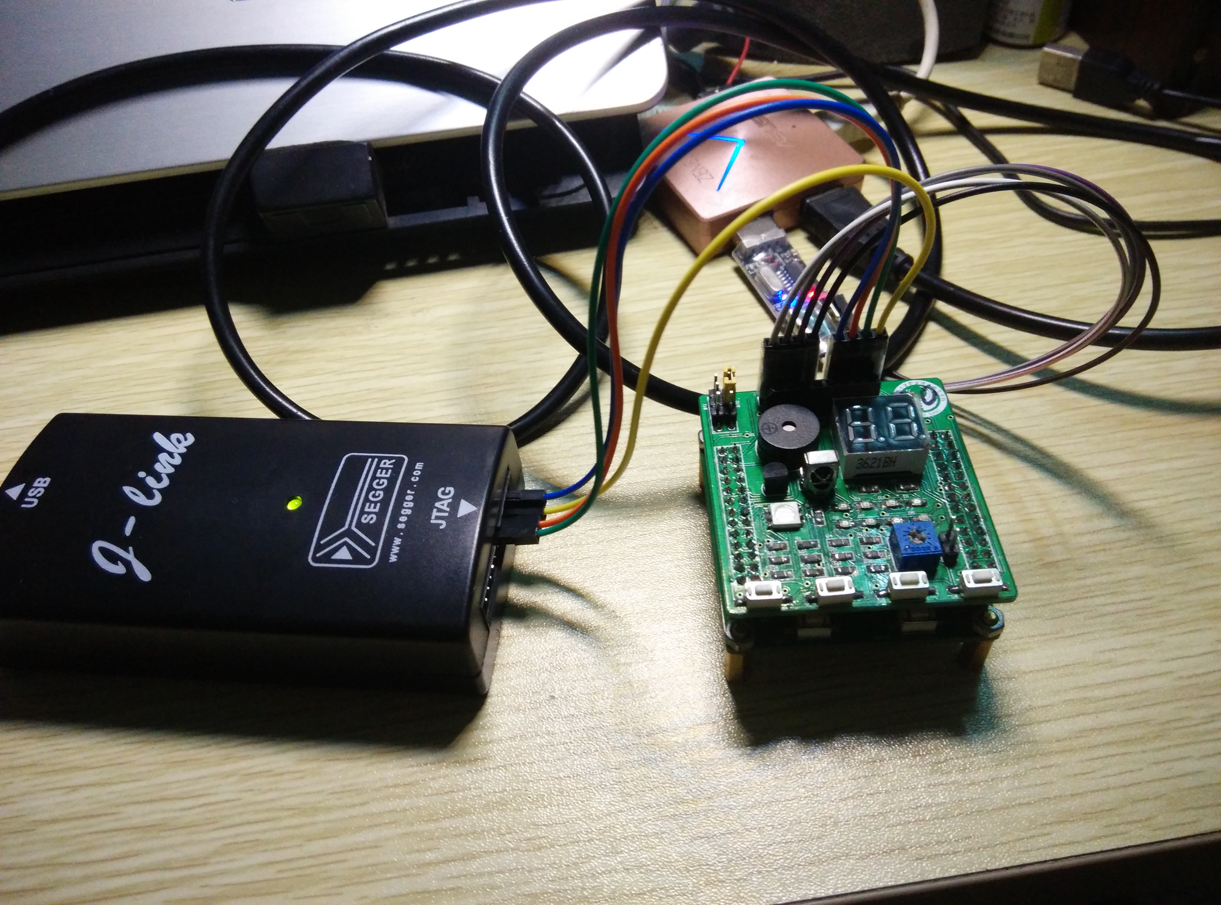
焊板的过程遇到挺多问题的,不过也学到了很多的东西,提高了自己的动手能力,对板也有了更多的了解。
总的来说焊电路板其实也是很有趣的
| 有奖活动 | |
|---|---|
| 5月直播——【探索边缘智能的未来——直播盛宴即将开启!】 | |
| 请大声喊出:我要开发板! | |
| 【有奖活动】EEPW网站征稿正在进行时,欢迎踊跃投稿啦 | |
| 【有奖活动】智能可穿戴设备AR/VR如何引领科技新潮流! | |
| 奖!发布技术笔记,技术评测贴换取您心仪的礼品 | |

 STM32
STM32 MCU
MCU 通讯及无线技术
 物联网技术
物联网技术 电子DIY
电子DIY 板卡试用
板卡试用 基础知识
基础知识 软件与操作系统
 我爱生活
我爱生活 小e食堂
小e食堂