
引言
1-Wire网络包括一个主机和一个或多个从机器件,1-Wire主机可以由微处理器的一个I/O引脚构成,手动产生定时脉冲。DS2482 I²C至1-Wire网络的桥接器件可以产生详细的1-Wire通信时序,无需工程师参与设计。图1所示为DS2482配置的简化框图。本文介绍了采用DS2482实现应用程序接口(API)有效方法,支持基本的和扩展的1-Wire操作。详细介绍了对应于1-Wire操作的I²C通信。这些操作为执行当前和未来1-Wire器件的所有功能打下了全面的基础,但基于DS250x系列EPROM的器件编程除外。以这种方式概要介绍1-Wire操作,适合不依赖1-Wire主机的1-Wire应用。
本文仅作为DS2482数据资料的补充,并不能替代数据资料。DS2482可提供两种配置,单通道1-Wire主控制器(DS2482-100)和带有低功耗休眠模式的1-Wire主控制器(DS2482-101),以及八通道1-Wire主控制器(DS2482-800)。
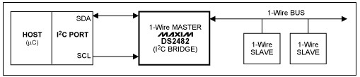
图1. 实现I²C与1-Wire网络通信的DS2482桥接器功能简图
下面给出几个基本的1-Wire函数,称之为原函数,也就是为了执行所有1-Wire操作,应用中必须具备的函数。第一个函数(OWReset)是使网络上所有1-Wire从器件复位,为接收来自1-Wire主控制器的指令做好准备。第二个函数(OWWriteBit)完成1-Wire主控制器向从器件写入一位的操作,而第三个函数(OWReadBit)完成从1-Wire从器件中读取一位的操作。由于必须由1-Wire主控制器启动所有的1-Wire位通信,所以“读取”实际上是在“写入”一位后采样得到的结果。几乎所有其他1-Wire操作都可以由这三个操作构成。例如,向1-Wire网络写1个字节相当于8次写一位操作。
1-Wire搜索算法也可以利用相同的三个原始函数构成。通1-Wire的三个命令,DS2482可以执行搜索功能,大大降低了搜索操作所需的通信量。同样,单字节的1-Wire通信命令要比八次逐位操作效率更高。
表1所示是三个基本原函数(OWReset、OWWriteBit/OWReadBit和OWWriteByte/OWReadByte)以及其它三个非常有用的函数(OWBlock、OWSearch和msDelay),它们构成了一系列主要的基本1-Wire操作。这些操作名称将在下文中使用。
表1. 基本的1-Wire操作
| Operation | Description |
| OWReset | Sends the 1-Wire reset stimulus and check for the presence pulse of 1-Wire slave devices. |
| OWWriteBit/OWReadBit | Sends to or receives from the 1-Wire network a single bit of data. |
| OWWriteByte/OWReadByte | Sends to or receives from the 1-Wire network a single byte of data. |
| OWBlock | Sends to and receives from the 1-Wire network multiple bytes of data. |
| OWSearch | Performs the 1-Wire Search Algorithm (see application note 187). |
| msDelay | Delays at least the specified number of milliseconds. Used for timing strong pullup operations. |
许多1-Wire从器件可以工作在两种不同的通信速率下:标准速率和高速模式。所有器件都支持标准速率模式。高速速率大约是标准速率的10倍。DS2482同时支持这两种1-Wire速率。
1-Wire器件通常从1-Wire总线上获取部分或全部工作电源。不过有些器件在协议的特定操作中需要额外供电。例如,某个器件可能需要进行温度转换或执行SHA-1散列算法。这种操作的电源是通过使能1-Wire总线的强上拉提供的。这种供电方式下,不能进行正常通信。DS2482通过设置强上拉标志(SPU)位供电,这将在1-Wire的下一个字节/位通信完成后启动强上拉。DS2482-100和DS2482-101还具有一个外部引脚(PCTLZ),可控制大电流强上拉。
表2列出了用于1-Wire速率设定、供电和编程脉冲的扩展1-Wire操作。
表2. 扩展的1-Wire操作
| Operation | Description |
| OWSpeed | Sets the 1-Wire communication speed, either standard or overdrive. Note that this only changes the communication speed of the 1-Wire master; the 1-Wire slave device must be instructed to make the switch when going from normal to overdrive. The 1-Wire slave will always revert to standard speed when it encounters a standard-speed 1-Wire reset. |
| OWLevel | Sets the 1-Wire power level (normal or power delivery). |
| OWReadBitPower | Reads a single bit of data from the 1-Wire network and optionally applies power delivery immediately after the bit is complete. |
| OWWriteBytePower | Sends a single byte of data to the 1-Wire network and applies power delivery immediately after the byte is complete. |
DS2482的主机应具有一个I²C通信口,本文并没有讲述主机的配置。然而,主机必须提供标准I²C接口操作。需要注意的是,主机接口具有包含一些I²C接口操作的高级函数。所需操作请参考表3。
表3. 所需要的I²C主机操作
| Operation | Description |
| I2C_start | I²C start command. |
| I2C_rep_start | I²C repeated start command. |
| I2C_stop | I²C stop command. |
| I2C_write | Writes a byte to the I²C bus. The byte to write is passed to the function. |
| I2C_read | Reads a byte from the I²C bus. The byte read is returned from the function. |
在尝试1-Wire操作之前,主机必须设置I²C至1-Wire线驱动器DS2482,并与其同步。要与DS2482通信,主机必须知道其从地址。图2所示为DS2482-100、DS2482-101和DS2482-800的从地址。
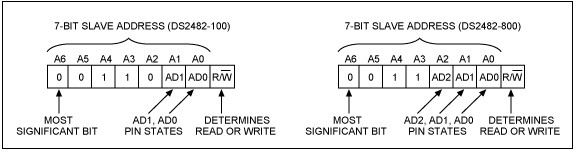
图2. DS2482的I²C从地址
下列符号说明来自于DS2482数据资料,以简写符号表示,用来说明器件的I²C通信过程。接下来,我们会重复这些通信过程,并为实现基本的和扩展的1-Wire操作提供附加注释和C语言例程。
I²C通信过程—符号说明
| Symbol | Description |
| S | START Condition |
| AD, 0 | Select DS2482 for Write Access |
| AD, 1 | Select DS2482 for Read Access |
| Sr | Repeated START Condition |
| P | STOP Condition |
| A | Acknowledged |
| A\ | Not acknowledged |
| (Idle) | Bus not busy |
| <byte> | Transfer of one byte |
| DRST | Command 'Device Reset', F0h |
| WCFG | Command 'Write Configuration', D2h |
| CHSL | Command 'Channel Select', C3h (DS2482-800 only) |
| SRP | Command 'Set Read Pointer', E1h |
| 1WRS | Command '1-Wire Reset', B4h |
| 1WWB | Command '1-Wire Write Byte', A5h |
| 1WRB | Command '1-Wire Read Byte', 96h |
| 1WSB | Command '1-Wire Single Bit', 87h |
| 1WT | Command '1-Wire Triplet', 78h |
| Master-to-Slave | Slave-to-Master |
本文中许多图中的数据方向表示方法指出了通信方向是主机到从机(灰色),还是从机到主机(白色)。 DS2482配置操作
以下操作用于设置、配置DS2482,有些操作需要调用1-Wire操作的子程序。
DS2482检测例1所示C程序提供检测和配置流程,写入DS2482的默认值包括1-Wire速率(标准)、强上拉(关断)、在线脉冲屏蔽(关断)和有源上拉(通)。该状态保持为通用变量,如果器件需要复位到该默认状态可以进行恢复。针对不同应用可以选择不同的默认值。
// DS2482 state
unsigned char I2C_address;
int c1WS, cSPU, cPPM, cAPU;
int short_detected;

//--------------------------------------------------------------------------
// DS2428 Detect routine that sets the I2C address and then performs a
// device reset followed by writing the configuration byte to default values:
//   1-Wire speed (c1WS) = standard (0)
//   Strong pullup (cSPU) = off (0)
//   Presence pulse masking (cPPM) = off (0)
//   Active pullup (cAPU) = on (CONFIG_APU = 0x01)
//
// Returns: TRUE if device was detected and written
//          FALSE device not detected or failure to write configuration byte
//
int DS2482_detect(unsigned char addr)
{
   // set global address
   I2C_address = addr;

   // reset the DS2482 ON selected address
   if (!DS2482_reset())
      return FALSE;

   // default configuration
   c1WS = FALSE;
   cSPU = FALSE;
   cPPM = FALSE;
   cAPU = CONFIG_APU;


   // write the default configuration setup
   if (!DS2482_write_config(c1WS | cSPU | cPPM | cAPU))
      return FALSE;

   return TRUE;
}
例1. DS2482检测
DS2482器件复位图3是DS2482器件复位I²C通信的流程。例2给出了DS2482复位命令的C程序,可实现器件状态机逻辑的完全复位,并终止所有正在进行的1-Wire通信。器件的复位命令代码是F0h。
![]()
图3. 上电后进行器件复位。该实例包括可选的读访问,以检验命令是否成功执行。
//--------------------------------------------------------------------------
// Perform a device reset on the DS2482
//
// Returns: TRUE if device was reset
//          FALSE device not detected or failure to perform reset
//
int DS2482_reset()
{
   unsigned char status;

   // Device Reset
   //   S AD,0 [A] DRST [A] Sr AD,1 [A] [SS] A\ P
   //  [] indicates from slave
   //  SS status byte to read to verify state

   I2C_start();
   I2C_write(I2C_address | I2C_WRITE, EXPECT_ACK);
   I2C_write(CMD_DRST, EXPECT_ACK);
   I2C_rep_start();
   I2C_write(I2C_address | I2C_READ, EXPECT_ACK);
   status = I2C_read(NACK);
   I2C_stop();

   // check for failure due to incorrect read back of status
   return ((status & 0xF7) == 0x10);
}
例2. 复位器件代码
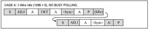
DS2482写配置图4所示为DS2482写配置的I²C通信例程;例3所示为实现DS2482写配置命令时序的C程序。写配置命令代码为D2h。
![]()
图4. 写配置寄存器,该实例中包括可选择的读操作,用于验证是否成功执行命令。
//--------------------------------------------------------------------------
// Write the configuration register in the DS2482. The configuration
// options are provided in the lower nibble of the provided config byte.
// The uppper nibble in bitwise inverted when written to the DS2482.
//
// Returns:  TRUE: config written and response correct
//           FALSE: response incorrect
//
int DS2482_write_config(unsigned char config)
{
   unsigned char read_config;

   // Write configuration (Case A)
   //   S AD,0 [A] WCFG [A] CF [A] Sr AD,1 [A] [CF] A\ P
   //  [] indicates from slave
   //  CF configuration byte to write

   I2C_start();
   I2C_write(I2C_address | I2C_WRITE, EXPECT_ACK);
   I2C_write(CMD_WCFG, EXPECT_ACK);
   I2C_write(config | (~config << 4), EXPECT_ACK);
   I2C_rep_start();
   I2C_write(I2C_address | I2C_READ, EXPECT_ACK);
   read_config = I2C_read(NACK);
   I2C_stop();

   // check for failure due to incorrect read back
   if (config != read_config)
   {
      // handle error
      // ...
      DS2482_reset();

      return FALSE;
   }

   return TRUE;
}
例3. DS2482写配置
DS2482通道选择图5所示为实现DS2482-800通道选择的I²C通信实例,有效通道为0至7。注意,该操作不适合DS2482-100或DS2482-101。例4给出了执行DS2482-800通道选择命令的C程序,通道选择命令码为C3h。选择通道后,选中通道可执行所有1-Wire操作。
![]()
图5. 写通道选择寄存器,该实例中包括可选择的读操作,用于验证是否成功执行命令。
//--------------------------------------------------------------------------
// Select the 1-Wire channel on a DS2482-800.
//
// Returns: TRUE if channel selected
//          FALSE device not detected or failure to perform select
//
int DS2482_channel_select(int channel)
{
   unsigned char ch, ch_read, check;

   // Channel Select (Case A)
   //   S AD,0 [A] CHSL [A] CC [A] Sr AD,1 [A] [RR] A\ P
   //  [] indicates from slave
   //  CC channel value
   //  RR channel read back

   I2C_start();
   I2C_write(I2C_address | I2C_WRITE, EXPECT_ACK);
   I2C_write(CMD_CHSL, EXPECT_ACK);

   switch (channel)
   {
      default: case 0: ch = 0xF0; ch_read = 0xB8; break;
      case 1: ch = 0xE1; ch_read = 0xB1; break;
      case 2: ch = 0xD2; ch_read = 0xAA; break;
      case 3: ch = 0xC3; ch_read = 0xA3; break;
      case 4: ch = 0xB4; ch_read = 0x9C; break;
      case 5: ch = 0xA5; ch_read = 0x95; break;
      case 6: ch = 0x96; ch_read = 0x8E; break;
      case 7: ch = 0x87; ch_read = 0x87; break;
   };

   I2C_write(ch, EXPECT_ACK);
   I2C_rep_start();
   I2C_write(I2C_address | I2C_READ, EXPECT_ACK);
   check = I2C_read(NACK);
   I2C_stop();

   // check for failure due to incorrect read back of channel
   return (check == ch_read);
}
例4. DS2482-800通道选择
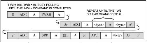
DS2482的1-Wire操作 OWReset1-Wire Reset命令(B4h)在1-Wire总线上执行1-Wire复位和1-Wire器件在线应答脉冲检测。通过状态寄存器中的在线应答脉冲检测(PPD)和短路检测(SD)字段,可以采样和报告1-Wire总线的状态。图6所示为1-Wire复位命令的I²C通信流程。例5为发送命令的C程序,将检查状态寄存器以确定在线应答脉冲状态。
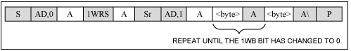
图6. 1-Wire复位。开始或终止1-Wire通信。连续检测1-Wire的空闲(1WB = 0)、忙状态,直到1-Wire命令完成为止,等到1-Wire命令执行完成,然后读取结果。
//--------------------------------------------------------------------------
// Reset all of the devices on the 1-Wire Net and return the result.
//
// Returns: TRUE(1):  presence pulse(s) detected, device(s) reset
//          FALSE(0): no presence pulses detected
//
int OWReset(void)
{
   unsigned char status;
   int poll_count = 0;

   // 1-Wire reset (Case B)
   //   S AD,0 [A] 1WRS [A] Sr AD,1 [A] [Status] A [Status] A\ P
   //                                   \--------/
   //                       Repeat until 1WB bit has changed to 0
   //  [] indicates from slave

   I2C_start();
   I2C_write(I2C_address | I2C_WRITE, EXPECT_ACK);
   I2C_write(CMD_1WRS, EXPECT_ACK);
   I2C_rep_start();
   I2C_write(I2C_address | I2C_READ, EXPECT_ACK);

   // loop checking 1WB bit for completion of 1-Wire operation
   // abort if poll limit reached
   status = I2C_read(ACK);
   do
   {
      status = I2C_read(status & STATUS_1WB);
   }
   while ((status & STATUS_1WB) && (poll_count++ < POLL_LIMIT));

   I2C_stop();

   // check for failure due to poll limit reached
   if (poll_count >= POLL_LIMIT)
   {
      // handle error
      // ...
      DS2482_reset();
      return FALSE;
   }

   // check for short condition
   if (status & STATUS_SD)
      short_detected = TRUE;
   else
      short_detected = FALSE;

   // check for presence detect
   if (status & STATUS_PPD)
      return TRUE;
   else
      return FALSE;
}
例5. OWReset代码
OWWriteBit/OWReadBit1-Wire位命令(0x87)生成一个1-Wire位时隙。图7所示是1-Wire位命令的I²C通信C程序。图8时字节的位分配,V是发送位。例6给出了OWWriteBit、OWReadBit和OWTouchBit程序。
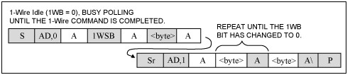
图7. 1-Wire位,在1-Wire总线上生成一个时隙,当1WB从1变为0时,状态寄存器保持1-Wire位命令的有效结果。
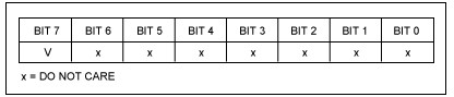
图8. 1-Wire的一个数据字节
//--------------------------------------------------------------------------
// Send 1 bit of communication to the 1-Wire Net.
// The parameter 'sendbit' least significant bit is used.
//
// 'sendbit' - 1 bit to send (least significant byte)
//
void OWWriteBit(unsigned char sendbit)
{
   OWTouchBit(sendbit);
}

//--------------------------------------------------------------------------
// Reads 1 bit of communication from the 1-Wire Net and returns the
// result
//
// Returns:  1 bit read from 1-Wire Net
//
unsigned char OWReadBit(void)
{
   return OWTouchBit(0x01);
}

//--------------------------------------------------------------------------
// Send 1 bit of communication to the 1-Wire Net and return the
// result 1 bit read from the 1-Wire Net. The parameter 'sendbit'
// least significant bit is used and the least significant bit
// of the result is the return bit.
//
// 'sendbit' - the least significant bit is the bit to send
//
// Returns: 0:   0 bit read from sendbit
//          1:   1 bit read from sendbit
//
unsigned char OWTouchBit(unsigned char sendbit)
{
   unsigned char status;
   int poll_count = 0;

   // 1-Wire bit (Case B)
   //   S AD,0 [A] 1WSB [A] BB [A] Sr AD,1 [A] [Status] A [Status] A\ P
   //                                          \--------/
   //                           Repeat until 1WB bit has changed to 0
   //  [] indicates from slave
   //  BB indicates byte containing bit value in msbit

   I2C_start();
   I2C_write(I2C_address | I2C_WRITE, EXPECT_ACK);
   I2C_write(CMD_1WSB, EXPECT_ACK);
   I2C_write(sendbit ? 0x80 : 0x00, EXPECT_ACK);
   I2C_rep_start();
   I2C_write(I2C_address | I2C_READ, EXPECT_ACK);

   // loop checking 1WB bit for completion of 1-Wire operation
   // abort if poll limit reached
   status = I2C_read(ACK);
   do
   {
      status = I2C_read(status & STATUS_1WB);
   }
   while ((status & STATUS_1WB) && (poll_count++ < POLL_LIMIT));

   I2C_stop();

   // check for failure due to poll limit reached
   if (poll_count >= POLL_LIMIT)
   {
      // handle error
      // ...
      DS2482_reset();
      return 0;
   }

   // return bit state
   if (status & STATUS_SBR)
      return 1;
   else
      return 0;
}
例6. 1-Wire位命令
OWWriteByte1-Wire写字节命令(A5h)向1-Wire总线写入单个数据字节。在DS2482执行该命令之前,必须结束1-Wire的工作状态。图9所示为通过I²C写1-Wire字节的情况。例7中的程序在从该操作返回前检查1-Wire是否完成有效的操作。
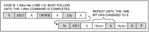
图9. 1-Wire写字节。向1-Wire总线发送命令代码。当1WB从1变为0时,完成1-Wire写字节命令。
//--------------------------------------------------------------------------
// Send 8 bits of communication to the 1-Wire Net and verify that the
// 8 bits read from the 1-Wire Net are the same (write operation).
// The parameter 'sendbyte' least significant 8 bits are used.
//
// 'sendbyte' - 8 bits to send (least significant byte)
//
// Returns:  TRUE: bytes written and echo was the same
//           FALSE: echo was not the same
//
void OWWriteByte(unsigned char sendbyte)
{
   unsigned char status;
   int poll_count = 0;

   // 1-Wire Write Byte (Case B)
   //   S AD,0 [A] 1WWB [A] DD [A] Sr AD,1 [A] [Status] A [Status] A\ P
   //                                          \--------/
   //                             Repeat until 1WB bit has changed to 0
   //  [] indicates from slave
   //  DD data to write

   I2C_start();
   I2C_write(I2C_address | I2C_WRITE, EXPECT_ACK);
   I2C_write(CMD_1WWB, EXPECT_ACK);
   I2C_write(sendbyte, EXPECT_ACK);
   I2C_rep_start();
   I2C_write(I2C_address | I2C_READ, EXPECT_ACK);

   // loop checking 1WB bit for completion of 1-Wire operation
   // abort if poll limit reached
   status = I2C_read(ACK);
   do
   {
      status = I2C_read(status & STATUS_1WB);
   }
   while ((status & STATUS_1WB) && (poll_count++ < POLL_LIMIT));

   I2C_stop();

   // check for failure due to poll limit reached
   if (poll_count >= POLL_LIMIT)
   {
      // handle error
      // ...
      DS2482_reset();
   }
} 
 我要赚赏金
我要赚赏金 STM32
STM32 MCU
MCU 通讯及无线技术
 物联网技术
物联网技术 电子DIY
电子DIY 板卡试用
板卡试用 基础知识
基础知识 软件与操作系统
 我爱生活
我爱生活 小e食堂
小e食堂

