
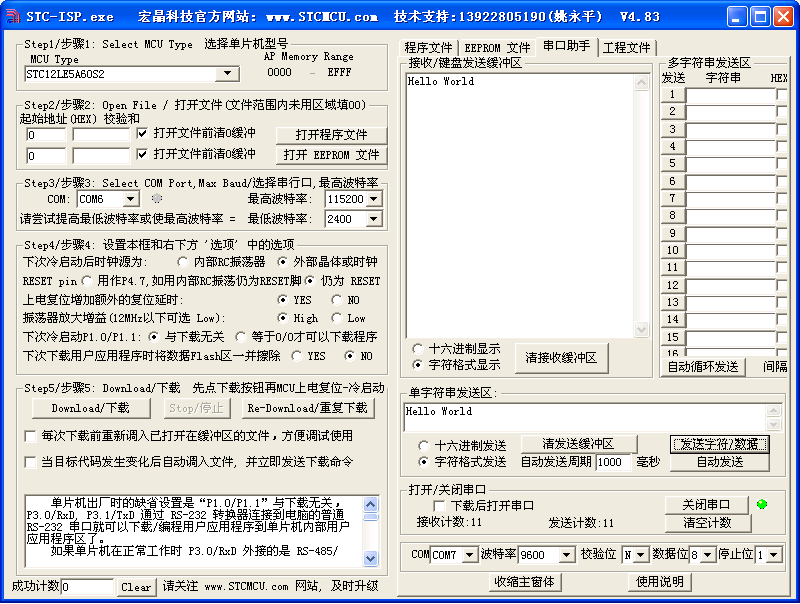
分别使用了查询方式和中断方式 串口1接收到数据后再发送出去
代码:
//Header:stm32f10x_conf.h
//FIle Name: main.c
//Author:
//Data:
#include "stm32f10x_conf.h" // 负责预编译头文件,
#include "stm32f10x.h"
#include "stm32f10x_it.h"
#include <stdio.h>
int useInt = 1; // 是否使用中断方式
int fputc(int ch, FILE *f);
void Uart1_PutChar(u8 ch);
void USART1_IRQHandler(void);
/*************************************************
函数: void RCC_Configuration(void)
功能: 复位和时钟控制 配置
参数: 无
返回: 无
**************************************************/
void RCC_Configuration(void)
{
ErrorStatus HSEStartUpStatus; //定义外部高速晶体启动状态枚举变量
RCC_DeInit(); //复位RCC外部设备寄存器到默认值
RCC_HSEConfig(RCC_HSE_ON); //打开外部高速晶振
HSEStartUpStatus = RCC_WaitForHSEStartUp(); //等待外部高速时钟准备好
if(HSEStartUpStatus == SUCCESS) //外部高速时钟已经准别好
{
FLASH_PrefetchBufferCmd(FLASH_PrefetchBuffer_Enable); //开启FLASH预读缓冲功能,加速FLASH的读取。所有程序中必须的用法.位置:RCC初始化子函数里面,时钟起振之后
FLASH_SetLatency(FLASH_Latency_2); //flash操作的延时
RCC_HCLKConfig(RCC_SYSCLK_Div1); //配置AHB(HCLK)时钟等于==SYSCLK
RCC_PCLK2Config(RCC_HCLK_Div1); //配置APB2(PCLK2)钟==AHB时钟
RCC_PCLK1Config(RCC_HCLK_Div2); //配置APB1(PCLK1)钟==AHB1/2时钟
RCC_PLLConfig(RCC_PLLSource_HSE_Div1, RCC_PLLMul_9); //配置PLL时钟 == 外部高速晶体时钟 * 9 = 72MHz
RCC_PLLCmd(ENABLE); //使能PLL时钟
while(RCC_GetFlagStatus(RCC_FLAG_PLLRDY) == RESET) //等待PLL时钟就绪
{
}
RCC_SYSCLKConfig(RCC_SYSCLKSource_PLLCLK); //配置系统时钟 = PLL时钟
while(RCC_GetSYSCLKSource() != 0x08) //检查PLL时钟是否作为系统时钟
{
}
}
}
void NVIC_Configuration(void)
{
NVIC_InitTypeDef NVIC_InitStructure;
/* Set the Vector Table base location at 0x08000000 */
NVIC_SetVectorTable(NVIC_VectTab_FLASH, 0x0);
/* Configure the NVIC Preemption Priority Bits */
NVIC_PriorityGroupConfig(NVIC_PriorityGroup_0);
/* Enable the USART1 Interrupt */
NVIC_InitStructure.NVIC_IRQChannel = USART1_IRQn; //通道设置为串口1中断
NVIC_InitStructure.NVIC_IRQChannelPreemptionPriority = 0; //中断占先等级0
NVIC_InitStructure.NVIC_IRQChannelSubPriority = 0; //中断响应优先级0
NVIC_InitStructure.NVIC_IRQChannelCmd = ENABLE; //打开中断
NVIC_Init(&NVIC_InitStructure); //初始化
}
/*******************************************************************************
函数名:USART1_Configuration
输 入:
输 出:
功能说明:
初始化串口硬件设备,启用中断
配置步骤:
(1)打开GPIO和USART1的时钟
(2)设置USART1两个管脚GPIO模式
(3)配置USART1数据格式、波特率等参数
(4)使能USART1接收中断功能
(5)最后使能USART1功能
*/
void USART1_Configuration(void)
{
GPIO_InitTypeDef GPIO_InitStructure;
USART_InitTypeDef USART_InitStructure;
/* 第1步:打开GPIO和USART部件的时钟 */
RCC_APB2PeriphClockCmd(RCC_APB2Periph_GPIOA | RCC_APB2Periph_AFIO, ENABLE);
RCC_APB2PeriphClockCmd(RCC_APB2Periph_USART1, ENABLE);
/* 第2步:将USART Tx的GPIO配置为推挽复用模式 */
GPIO_InitStructure.GPIO_Pin = GPIO_Pin_9;
GPIO_InitStructure.GPIO_Mode = GPIO_Mode_AF_PP;
GPIO_InitStructure.GPIO_Speed = GPIO_Speed_50MHz;
GPIO_Init(GPIOA, &GPIO_InitStructure);
/* 第3步:将USART Rx的GPIO配置为浮空输入模式
由于CPU复位后,GPIO缺省都是浮空输入模式,因此下面这个步骤不是必须的
但是,我还是建议加上便于阅读,并且防止其它地方修改了这个口线的设置参数
*/
GPIO_InitStructure.GPIO_Pin = GPIO_Pin_10;
GPIO_InitStructure.GPIO_Mode = GPIO_Mode_IN_FLOATING;
GPIO_Init(GPIOA, &GPIO_InitStructure);
GPIO_InitStructure.GPIO_Speed = GPIO_Speed_50MHz;
GPIO_Init(GPIOA, &GPIO_InitStructure);
/* 第4步:配置USART1参数
- BaudRate = 115200 baud
- Word Length = 8 Bits
- One Stop Bit
- No parity
- Hardware flow control disabled (RTS and CTS signals)
- Receive and transmit enabled
*/
USART_InitStructure.USART_BaudRate = 9600;
USART_InitStructure.USART_WordLength = USART_WordLength_8b;
USART_InitStructure.USART_StopBits = USART_StopBits_1;
USART_InitStructure.USART_Parity = USART_Parity_No;
USART_InitStructure.USART_HardwareFlowControl = USART_HardwareFlowControl_None;
USART_InitStructure.USART_Mode = USART_Mode_Rx | USART_Mode_Tx;
USART_Init(USART1, &USART_InitStructure);
/* 若接收数据寄存器满,则产生中断 */
if(useInt)
USART_ITConfig(USART1, USART_IT_RXNE, ENABLE);
/* 第5步:使能 USART1, 配置完毕 */
USART_Cmd(USART1, ENABLE);
/* 如下语句解决第1个字节无法正确发送出去的问题 */
USART_ClearFlag(USART1, USART_FLAG_TC); // 清标志
}
int main(void)
{
u8 revData;
RCC_Configuration();
if(useInt)
NVIC_Configuration();
USART1_Configuration();
while(1)
{
if(!useInt)
{
while(USART_GetFlagStatus(USART1, USART_FLAG_RXNE) == RESET); //等待接收完毕
revData = USART_ReceiveData(USART1); //接受一个字节
// 把接收到的字符发送出去
Uart1_PutChar(revData);
}
}
return 1;
}
int fputc(int ch, FILE *f)
{
USART_SendData(USART1, (uint8_t) ch); /*发送一个字符函数*/
/* Loop until the end of transmission */
while (USART_GetFlagStatus(USART1, USART_FLAG_TC) == RESET)/*等待发送完成*/
{
}
return ch;
}
void Uart1_PutChar(u8 ch)
{
USART_SendData(USART1, (u8) ch);
while(USART_GetFlagStatus(USART1, USART_FLAG_TXE) == RESET);
}
/*******************************************************************/
/* */
/* STM32在串口1接收1字节 */
/* 说明:串口1接收中断 */
/* */
/*******************************************************************/
void USART1_IRQHandler(void) //在中断服务程序中,由于主机响应中断时并不知道是哪个中断源发出中断请求,因此必须在中断服务程序中对中断源进行判别,然后分别进行处理。当然,如果只涉及到一个中断请求,是不用做上述判别的。但是无论什么情况,做上述判别是个好习惯
{
u8 dat;
if(USART_GetITStatus(USART1, USART_IT_RXNE) != RESET) //若接收数据寄存器满
{
dat = USART_ReceiveData(USART1);
Uart1_PutChar(dat);
}
}
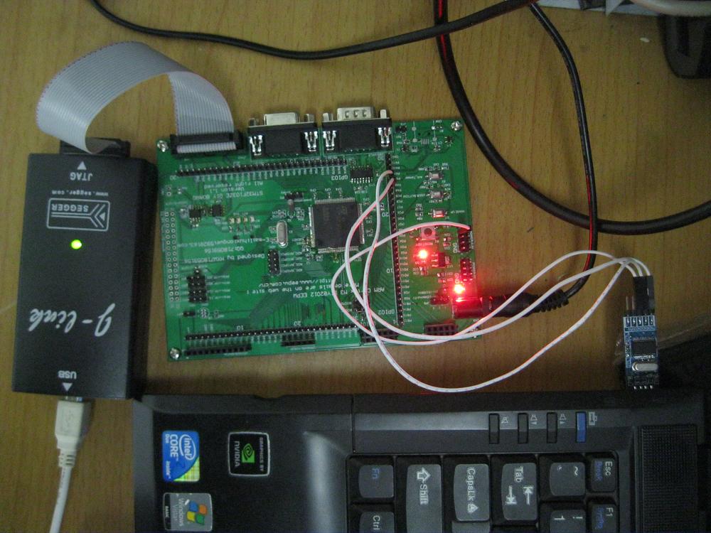
jlink下载
Build target 'Target 1'
linking...
Program Size: Code=6240 RO-data=268 RW-data=28 ZI-data=516
FromELF: creating hex file...
".\obj\My_Prj_Template.axf" - 0 Error(s), 0 Warning(s).
Load "D:\\STM32Proj\\My_Stm_Com\\obj\\My_Prj_Template.AXF"
Set JLink Project File to "D:\STM32Proj\My_Stm_Com\JLinkSettings.ini"
JLink info:
------------
DLL: V4.24b, compiled Feb 22 2011 20:47:17
Firmware: J-Link ARM V8 compiled Jan 31 2011 18:34:52
Hardware: V8.00
S/N : 20100214
Feature(s) : RDI,FlashDL,FlashBP,JFlash,GDBFull
* JLink Info: TotalIRLen = 9, IRPrint = 0x0011
* JLink Info: Found Cortex-M3 r1p1, Little endian.
* JLink Info: TPIU fitted.
* JLink Info: ETM fitted.
* JLink Info: FPUnit: 6 code (BP) slots and 2 literal slots
ROMTableAddr = 0xE00FF003
* JLink Info: TotalIRLen = 9, IRPrint = 0x0011
* JLink Info: Found Cortex-M3 r1p1, Little endian.
* JLink Info: TPIU fitted.
* JLink Info: ETM fitted.
* JLink Info: FPUnit: 6 code (BP) slots and 2 literal slots
* JLink Info: TotalIRLen = 9, IRPrint = 0x0011
* JLink Info: Found Cortex-M3 r1p1, Little endian.
* JLink Info: TPIU fitted.
* JLink Info: ETM fitted.
* JLink Info: FPUnit: 6 code (BP) slots and 2 literal slots
Target info:
------------
Device: STM32F103ZE
VTarget = 3.584V
State of Pins:
TCK: 1, TDI: 0, TDO: 1, TMS: 0, TRES: 1, TRST: 1
Hardware-Breakpoints: 6
Software-Breakpoints: 2048
Watchpoints: 4
JTAG speed: 2000 kHz
Erase Done.
Programming Done.
Verify OK.
运行截图:
实现现场:
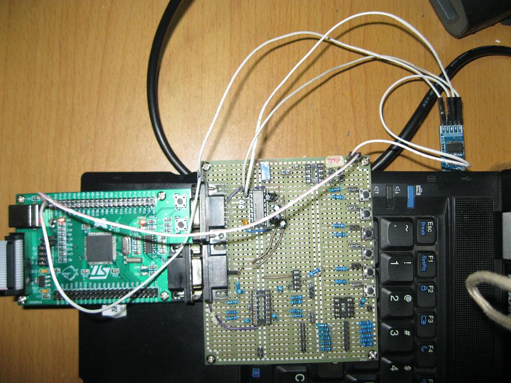
此外对别人的一个STM32F103VBT6最小系统板子做了串口下载 用的是USB转串口
 我要赚赏金
我要赚赏金 STM32
STM32 MCU
MCU 通讯及无线技术
 物联网技术
物联网技术 电子DIY
电子DIY 板卡试用
板卡试用 基础知识
基础知识 软件与操作系统
 我爱生活
我爱生活 小e食堂
小e食堂

