
ADC&RGB
这是在之前PWM的基础上简单更改的,加上了ADC的结构体 初始化 还有一些参数,就可以简单控制RGB的颜色了
视频后面再贴
/* Includes ------------------------------------------------------------------*/
#include "stm32f10x.h"
#include "stm32_eval.h"
#include <stdio.h>
#define VREF 3.3
/** @addtogroup STM32F10x_StdPeriph_Examples
* @{
*/
/** @addtogroup EXTI_Config
* @{
*/
/* Private typedef -----------------------------------------------------------*/
/* Private define ------------------------------------------------------------*/
/* Private macro -------------------------------------------------------------*/
/* Private variables ---------------------------------------------------------*/
GPIO_InitTypeDef GPIO_InitStructure;
USART_InitTypeDef USART_InitStructure;
USART_ClockInitTypeDef USART_ClockInitStructure;
void RCC_Configuration(void)
{
SystemInit();
RCC_APB2PeriphClockCmd(RCC_APB2Periph_GPIOD|RCC_APB2Periph_AFIO, ENABLE);
GPIO_PinRemapConfig(GPIO_Remap_SWJ_JTAGDisable,ENABLE);//disable JTAG
RCC_APB2PeriphClockCmd(RCC_APB2Periph_GPIOD|RCC_APB2Periph_AFIO, ENABLE);
GPIO_PinRemapConfig(GPIO_Remap_SWJ_JTAGDisable,ENABLE);//disable JTAG
GPIO_InitStructure.GPIO_Pin = GPIO_Pin_2;
GPIO_InitStructure.GPIO_Speed = GPIO_Speed_50MHz;
GPIO_InitStructure.GPIO_Mode = GPIO_Mode_Out_PP;
GPIO_Init(GPIOD, &GPIO_InitStructure);
GPIO_ResetBits(GPIOD,GPIO_Pin_2);
RCC_APB2PeriphClockCmd(RCC_APB2Periph_GPIOC|RCC_APB2Periph_AFIO, ENABLE);
GPIO_PinRemapConfig(GPIO_Remap_SWJ_JTAGDisable,ENABLE);//disable JTAG
RCC_APB1PeriphClockCmd(RCC_APB1Periph_TIM2, ENABLE);
}
void USART_int(long BaudRate)
{
RCC_APB2PeriphClockCmd(RCC_APB2Periph_GPIOA|RCC_APB2Periph_USART1,ENABLE);
GPIO_InitStructure.GPIO_Pin = GPIO_Pin_9;
GPIO_InitStructure.GPIO_Speed = GPIO_Speed_10MHz;
GPIO_InitStructure.GPIO_Mode = GPIO_Mode_AF_PP;
GPIO_Init(GPIOA, &GPIO_InitStructure);
/* PA10 USART1_Rx */
GPIO_InitStructure.GPIO_Pin = GPIO_Pin_10;
GPIO_InitStructure.GPIO_Mode = GPIO_Mode_IN_FLOATING;
GPIO_Init(GPIOA, &GPIO_InitStructure);
/* USARTx configured as follow:
- BaudRate = 115200 baud
- Word Length = 8 Bits
- One Stop Bit
- No parity
- Hardware flow control disabled (RTS and CTS signals)
- Receive and transmit enabled
*/
USART_InitStructure.USART_BaudRate = BaudRate;//??????
USART_InitStructure.USART_WordLength = USART_WordLength_8b;//???????8bit
USART_InitStructure.USART_StopBits = USART_StopBits_1;//????1
USART_InitStructure.USART_Parity = USART_Parity_No;//????
USART_InitStructure.USART_HardwareFlowControl = USART_HardwareFlowControl_None;//??????none
USART_InitStructure.USART_Mode = USART_Mode_Rx | USART_Mode_Tx;//??????????
USART_ClockInitStructure.USART_Clock = USART_Clock_Disable;
USART_ClockInitStructure.USART_CPOL = USART_CPOL_Low;
USART_ClockInitStructure.USART_CPHA = USART_CPHA_2Edge;
USART_ClockInitStructure.USART_LastBit = USART_LastBit_Disable;
USART_ClockInit(USART1, &USART_ClockInitStructure);
USART_Init(USART1, &USART_InitStructure);
USART_Cmd(USART1, ENABLE);
USART_ITConfig(USART1, USART_IT_RXNE, ENABLE);
USART_Cmd(USART1, ENABLE);
}
void delay_us(u32 n)
{
u8 j;
while(n--)
for(j=0;j<10;j++);
}
void delay_ms(u32 n)
{
while(n--)
delay_us(1000);
}
void PWM_Config()
{uint16_t PrescalerValue = 0;
TIM_TimeBaseInitTypeDef TIM_TimeBaseStructure;
TIM_OCInitTypeDef TIM_OCInitStructure;
/* TIM2 clock enable */
RCC_APB1PeriphClockCmd(RCC_APB1Periph_TIM2, ENABLE);
/* GPIOA enable */
RCC_APB2PeriphClockCmd(RCC_APB2Periph_AFIO , ENABLE);
GPIO_InitStructure.GPIO_Pin = GPIO_Pin_1|GPIO_Pin_2|GPIO_Pin_3;
GPIO_InitStructure.GPIO_Mode = GPIO_Mode_AF_PP;
GPIO_InitStructure.GPIO_Speed = GPIO_Speed_50MHz;
GPIO_Init(GPIOA, &GPIO_InitStructure);
TIM_Cmd(TIM2, ENABLE);
/* Compute the prescaler value */
PrescalerValue = (uint16_t) (SystemCoreClock / 24000000) - 1;
/* Time base configuration */
TIM_TimeBaseStructure.TIM_Period = 0x07FF;
TIM_TimeBaseStructure.TIM_Prescaler = PrescalerValue;
TIM_TimeBaseStructure.TIM_ClockDivision = 0;
TIM_TimeBaseStructure.TIM_CounterMode = TIM_CounterMode_Up;
TIM_TimeBaseInit(TIM2, &TIM_TimeBaseStructure);
TIM_OCInitStructure.TIM_OCMode = TIM_OCMode_PWM1;
TIM_OCInitStructure.TIM_OCPolarity = TIM_OCPolarity_High;
/* PWM1 Mode configuration: Channel2 */
TIM_OCInitStructure.TIM_OutputState = TIM_OutputState_Enable;
TIM_OCInitStructure.TIM_Pulse = 0xFFFF;
TIM_OC2Init(TIM2, &TIM_OCInitStructure);
/* PWM1 Mode configuration: Channel3 */
TIM_OCInitStructure.TIM_OutputState = TIM_OutputState_Enable;
TIM_OCInitStructure.TIM_Pulse = 0xFFFF;
TIM_OC3Init(TIM2, &TIM_OCInitStructure);
/* PWM1 Mode configuration: Channel4 */
TIM_OCInitStructure.TIM_OutputState = TIM_OutputState_Enable;
TIM_OCInitStructure.TIM_Pulse = 0xFFFF;
TIM_OC4Init(TIM2, &TIM_OCInitStructure);
TIM_ARRPreloadConfig(TIM2, ENABLE);
}
void ADC_CONFIG(){
ADC_InitTypeDef ADC_InitStructure;
#if defined (STM32F10X_LD_VL) || defined (STM32F10X_MD_VL) || defined (STM32F10X_HD_VL)
/* ADCCLK = PCLK2/2 */
RCC_ADCCLKConfig(RCC_PCLK2_Div2); //复位ADC1,同时设置分频因子
#else
/* ADCCLK = PCLK2/4 */
RCC_ADCCLKConfig(RCC_PCLK2_Div4);
#endif
ADC_DeInit(ADC1);
/* Enable ADC1 and GPIOC clock */
RCC_APB2PeriphClockCmd(RCC_APB2Periph_ADC1 | RCC_APB2Periph_GPIOB, ENABLE);
/* Configure PB0 (ADC Channel14) as analog input -------------------------*/
GPIO_InitStructure.GPIO_Pin = GPIO_Pin_0;
GPIO_InitStructure.GPIO_Mode = GPIO_Mode_AIN;
GPIO_Init(GPIOB, &GPIO_InitStructure);
/* ADC1 configuration ------------------------------------------------------*/
ADC_InitStructure.ADC_Mode = ADC_Mode_Independent; //ADC工作模式:独立模式
ADC_InitStructure.ADC_ScanConvMode = ENABLE; //AD单通道模式
ADC_InitStructure.ADC_ContinuousConvMode = ENABLE; //AD单次转换模式
ADC_InitStructure.ADC_ExternalTrigConv = ADC_ExternalTrigConv_None; //转换由软件而不是外部触发启动
ADC_InitStructure.ADC_DataAlign = ADC_DataAlign_Right; //ADC数据右对齐
ADC_InitStructure.ADC_NbrOfChannel = 1; //顺序进行规则转换的ADC通道的数目1
ADC_Init(ADC1, &ADC_InitStructure); //根据指定参数初始化外设ADC1
/* Enable ADC1 DMA */
ADC_DMACmd(ADC1, ENABLE);
/* Enable ADC1 */
ADC_Cmd(ADC1, ENABLE);
}
int Get_ADC(){
/* ADC1 regular channel configuration */
ADC_RegularChannelConfig(ADC1, ADC_Channel_8, 1, ADC_SampleTime_55Cycles5); //规则序列中的第1个转换,采样周期为55.5
/* Enable ADC1 reset calibration register */
ADC_ResetCalibration(ADC1); //执行复位校准
/* Check the end of ADC1 reset calibration register */
while(ADC_GetResetCalibrationStatus(ADC1));
/* Start ADC1 calibration */
ADC_StartCalibration(ADC1); //执行ADC校准,开始指定的ADC1的校准状态
/* Check the end of ADC1 calibration */
while(ADC_GetCalibrationStatus(ADC1));
/* Start ADC1 Software Conversion */
ADC_SoftwareStartConvCmd(ADC1, ENABLE); //软件开启ADC转换
return ADC_GetConversionValue(ADC1);
}
void PWM_TEST()
{
float Volt=0.00;
unsigned int temp0,temp1,temp2,ADValue = 0;
while(1)
{
ADValue = Get_ADC();
Volt = VREF*ADValue/4095;
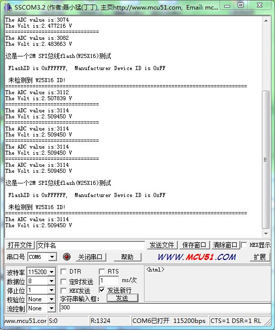
printf("PWM-RGB & ADC TEST......\r\n\r\n");
printf("The ADC value is:%d\r\n",ADValue);
printf("The Volt is:%f V\r\n",Volt);
TIM_SetCompare2(TIM2, temp0);
TIM_SetCompare3(TIM2, temp1);
TIM_SetCompare4(TIM2, temp2);
if(ADValue>3000)
{ temp0=ADValue/2;temp1=ADValue/2;temp2=ADValue/2-1500;
}
if(2000<ADValue<=3000)
{ temp0=ADValue/2;temp1=ADValue/2-1000;temp2=ADValue/2;
}
if(1000<ADValue<=2000)
{ temp0=ADValue/2+1000;temp1=ADValue/2;temp2=ADValue/2;
}
if(ADValue<=1000)
{ temp0=ADValue+500;temp1=ADValue+1500;temp2=ADValue+1000;
}
delay_ms(50);
}
}
/* Private functions ---------------------------------------------------------*/
/**
* @brief Main program.
* @param None
* @retval None
*/
int main(void)
{
RCC_Configuration();
USART_int(115200);
ADC_CONFIG();
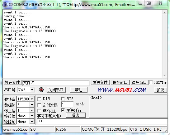
printf(" config done...\r\n");
Get_ADC();
PWM_Config();
delay_ms(200);
while(1)
{
PWM_TEST();
}
}
#ifdef USE_FULL_ASSERT
void assert_failed(uint8_t* file, uint32_t line)
{
while (1)
{
}
}
#endif
/**
* @}
*/
/**
* @}
*/
#ifdef __GNUC__
/* With GCC/RAISONANCE, small printf (option LD Linker->Libraries->Small printf
set to 'Yes') calls __io_putchar() */
#define PUTCHAR_PROTOTYPE int __io_putchar(int ch)
#else
#define PUTCHAR_PROTOTYPE int fputc(int ch, FILE *f)
#endif /* __GNUC__ */
PUTCHAR_PROTOTYPE
{
/* Place your implementation of fputc here */
/* e.g. write a character to the USART */
USART_SendData(EVAL_COM1, (uint8_t) ch);
/* Loop until the end of transmission */
while (USART_GetFlagStatus(EVAL_COM1, USART_FLAG_TC) == RESET)
{}
return ch;
}
#ifdef USE_FULL_ASSERT
void assert_failed(uint8_t* file, uint32_t line)
{
while (1)
{
}
}
#endif

 我要赚赏金
我要赚赏金 STM32
STM32 MCU
MCU 通讯及无线技术
 物联网技术
物联网技术 电子DIY
电子DIY 板卡试用
板卡试用 基础知识
基础知识 软件与操作系统
 我爱生活
我爱生活 小e食堂
小e食堂

