
#include "stm32f10x.h"
#include "stm32_eval.h"
#include <stdio.h>
#define VREF 3.3
unsigned char i=0;
void EXTIkeyS1_Config(void);
/* Private typedef -----------------------------------------------------------*/
/* Private define ------------------------------------------------------------*/
/* Private macro -------------------------------------------------------------*/
/* Private variables ---------------------------------------------------------*/
GPIO_InitTypeDef   GPIO_InitStructure;
USART_InitTypeDef USART_InitStructure;
USART_ClockInitTypeDef USART_ClockInitStructure;
EXTI_InitTypeDef   EXTI_InitStructure;
NVIC_InitTypeDef   NVIC_InitStructure;
void RCC_Configuration(void)
{
  RCC_DeInit();
  RCC_HSICmd(ENABLE);
  while(RCC_GetFlagStatus(RCC_FLAG_HSIRDY) == RESET);
  RCC_SYSCLKConfig(RCC_SYSCLKSource_HSI);
  RCC_HSEConfig(RCC_HSE_OFF);
  RCC_LSEConfig(RCC_LSE_OFF);
  RCC_PLLConfig(RCC_PLLSource_HSI_Div2,RCC_PLLMul_9); //  72HMz
  RCC_PLLCmd(ENABLE);
  while(RCC_GetFlagStatus(RCC_FLAG_PLLRDY) == RESET);
  RCC_ADCCLKConfig(RCC_PCLK2_Div4);
  RCC_PCLK2Config(RCC_HCLK_Div1);
  RCC_PCLK1Config(RCC_HCLK_Div2);
  RCC_HCLKConfig(RCC_SYSCLK_Div1);
  RCC_SYSCLKConfig(RCC_SYSCLKSource_PLLCLK);
  while(RCC_GetSYSCLKSource() != 0x08);
    //SystemInit();
    RCC_APB2PeriphClockCmd(RCC_APB2Periph_GPIOD|RCC_APB2Periph_AFIO, ENABLE);
  GPIO_PinRemapConfig(GPIO_Remap_SWJ_JTAGDisable,ENABLE);//disable JTAG
  RCC_APB2PeriphClockCmd(RCC_APB2Periph_GPIOD|RCC_APB2Periph_AFIO, ENABLE);
  GPIO_PinRemapConfig(GPIO_Remap_SWJ_JTAGDisable,ENABLE);//disable JTAG
  GPIO_InitStructure.GPIO_Pin = GPIO_Pin_2;
  GPIO_InitStructure.GPIO_Speed = GPIO_Speed_50MHz;
  GPIO_InitStructure.GPIO_Mode = GPIO_Mode_Out_PP;
  GPIO_Init(GPIOD, &GPIO_InitStructure);
    GPIO_ResetBits(GPIOD,GPIO_Pin_2);
    RCC_APB2PeriphClockCmd(RCC_APB2Periph_GPIOC|RCC_APB2Periph_AFIO, ENABLE);
  GPIO_PinRemapConfig(GPIO_Remap_SWJ_JTAGDisable,ENABLE);//disable JTAG
  GPIO_InitStructure.GPIO_Pin = GPIO_Pin_0|GPIO_Pin_1|GPIO_Pin_2|GPIO_Pin_3|GPIO_Pin_4|GPIO_Pin_5|GPIO_Pin_6|GPIO_Pin_7;
  GPIO_InitStructure.GPIO_Speed = GPIO_Speed_50MHz;
  GPIO_InitStructure.GPIO_Mode = GPIO_Mode_Out_PP;
  GPIO_Init(GPIOC, &GPIO_InitStructure);
    GPIO_SetBits(GPIOC,GPIO_Pin_0|GPIO_Pin_1|GPIO_Pin_2|GPIO_Pin_3|GPIO_Pin_4|GPIO_Pin_5|GPIO_Pin_6|GPIO_Pin_7);
      RCC_APB1PeriphClockCmd(RCC_APB1Periph_TIM2, ENABLE);
}

void USART_int(long BaudRate)
{
      RCC_APB2PeriphClockCmd(RCC_APB2Periph_GPIOA|RCC_APB2Periph_USART1,ENABLE);
    GPIO_InitStructure.GPIO_Pin = GPIO_Pin_9;
    GPIO_InitStructure.GPIO_Speed = GPIO_Speed_50MHz;
    GPIO_InitStructure.GPIO_Mode = GPIO_Mode_AF_PP;
    GPIO_Init(GPIOA, &GPIO_InitStructure);
    /* PA10 USART1_Rx  */
    GPIO_InitStructure.GPIO_Pin = GPIO_Pin_10;
    GPIO_InitStructure.GPIO_Mode = GPIO_Mode_IN_FLOATING;
    GPIO_Init(GPIOA, &GPIO_InitStructure);
  /* USARTx configured as follow:
        - BaudRate = 115200 baud
        - Word Length = 8 Bits
        - One Stop Bit
        - No parity
        - Hardware flow control disabled (RTS and CTS signals)
        - Receive and transmit enabled
  */
  USART_InitStructure.USART_BaudRate = BaudRate;//??????
  USART_InitStructure.USART_WordLength = USART_WordLength_8b;//???????8bit
  USART_InitStructure.USART_StopBits = USART_StopBits_1;//????1
  USART_InitStructure.USART_Parity = USART_Parity_No;//????
  USART_InitStructure.USART_HardwareFlowControl = USART_HardwareFlowControl_None;//??????none
  USART_InitStructure.USART_Mode = USART_Mode_Rx | USART_Mode_Tx;//??????????
    USART_ClockInitStructure.USART_Clock = USART_Clock_Disable;
    USART_ClockInitStructure.USART_CPOL = USART_CPOL_Low;
    USART_ClockInitStructure.USART_CPHA = USART_CPHA_2Edge;
    USART_ClockInitStructure.USART_LastBit = USART_LastBit_Disable;
    USART_ClockInit(USART1, &USART_ClockInitStructure);
  USART_Init(USART1, &USART_InitStructure);
  USART_Cmd(USART1, ENABLE);
    USART_ITConfig(USART1, USART_IT_RXNE, ENABLE);
  USART_Cmd(USART1, ENABLE);
      /* Configure four bit for preemption priority */
  NVIC_PriorityGroupConfig(NVIC_PriorityGroup_4);
  /* Enable the USART1 Interrupt */
  NVIC_InitStructure.NVIC_IRQChannel = USART1_IRQn; //
  NVIC_InitStructure.NVIC_IRQChannelPreemptionPriority = 15;
  NVIC_InitStructure.NVIC_IRQChannelCmd = ENABLE;
  NVIC_Init(&NVIC_InitStructure);
}

void IIc2_Init(void)
{
        GPIO_InitTypeDef GPIO_InitStructure;
        I2C_InitTypeDef I2C_InitStructure;

        RCC_APB2PeriphClockCmd(RCC_APB2Periph_GPIOB, ENABLE);
        RCC_APB1PeriphClockCmd(RCC_APB1Periph_I2C2, ENABLE);
        //PB6-I2C2_SCL PB7-I2C2_SDA PB10-I2C2_SCL PB11-I2C2_SDA
        /* Configure IO connected to IIC*********************/
        GPIO_InitStructure.GPIO_Pin =  GPIO_Pin_10 | GPIO_Pin_11;
        GPIO_InitStructure.GPIO_Speed = GPIO_Speed_50MHz;
        GPIO_InitStructure.GPIO_Mode = GPIO_Mode_AF_OD;
        GPIO_Init(GPIOB, &GPIO_InitStructure);

        I2C_InitStructure.I2C_Mode = I2C_Mode_I2C;
        I2C_InitStructure.I2C_DutyCycle = I2C_DutyCycle_2;
        I2C_InitStructure.I2C_OwnAddress1 = 0xA0;
        I2C_InitStructure.I2C_Ack = I2C_Ack_Enable;
        I2C_InitStructure.I2C_AcknowledgedAddress = I2C_AcknowledgedAddress_7bit;
        I2C_InitStructure.I2C_ClockSpeed = 400000;
        I2C_Cmd(I2C2, ENABLE);
        I2C_Init(I2C2, &I2C_InitStructure);
        I2C_AcknowledgeConfig(I2C2, ENABLE);
}

void I2C2_WriteByte(unsigned char id,unsigned char write_address,unsigned char byte)
{
        while(I2C_GetFlagStatus(I2C2, I2C_FLAG_BUSY));
        I2C_GenerateSTART(I2C2,ENABLE);
        while(!I2C_CheckEvent(I2C2, I2C_EVENT_MASTER_MODE_SELECT));
        I2C_Send7bitAddress(I2C2,id,I2C_Direction_Transmitter);
        while(!I2C_CheckEvent(I2C2, I2C_EVENT_MASTER_TRANSMITTER_MODE_SELECTED));
        I2C_SendData(I2C2, write_address);
        while(!I2C_CheckEvent(I2C2, I2C_EVENT_MASTER_BYTE_TRANSMITTED));
        I2C_SendData(I2C2, byte);
        while(!I2C_CheckEvent(I2C2, I2C_EVENT_MASTER_BYTE_TRANSMITTED));
        I2C_GenerateSTOP(I2C2, ENABLE);
        do
        {
           /* Send START condition */
           I2C_GenerateSTART(I2C2, ENABLE);
          /* Read I2C2 SR1 register */
            /* Send EEPROM address for write */
            I2C_Send7bitAddress(I2C2, 0xA0, I2C_Direction_Transmitter);
        }while(!(I2C_ReadRegister(I2C2, I2C_Register_SR1) & 0x0002));

        /* Clear AF flag */
        I2C_ClearFlag(I2C2, I2C_FLAG_AF);
        /* STOP condition */
        I2C_GenerateSTOP(I2C2, ENABLE);
}

unsigned char I2C2_ReadByte(unsigned char  id, unsigned char read_address)
{
     unsigned char temp;
     while(I2C_GetFlagStatus(I2C2, I2C_FLAG_BUSY)){}
     I2C_GenerateSTART(I2C2, ENABLE);
     while(!I2C_CheckEvent(I2C2, I2C_EVENT_MASTER_MODE_SELECT));
     I2C_Send7bitAddress(I2C2, id, I2C_Direction_Transmitter);
     while(!I2C_CheckEvent(I2C2, I2C_EVENT_MASTER_TRANSMITTER_MODE_SELECTED));
     I2C_Cmd(I2C2, ENABLE);
     I2C_SendData(I2C2, read_address);
     while(!I2C_CheckEvent(I2C2, I2C_EVENT_MASTER_BYTE_TRANSMITTED));
     I2C_GenerateSTART(I2C2, ENABLE);
     while(!I2C_CheckEvent(I2C2, I2C_EVENT_MASTER_MODE_SELECT));
     I2C_Send7bitAddress(I2C2, id, I2C_Direction_Receiver);
     while(!I2C_CheckEvent(I2C2, I2C_EVENT_MASTER_RECEIVER_MODE_SELECTED));
    I2C_AcknowledgeConfig(I2C2, DISABLE);
    I2C_GenerateSTOP(I2C2, ENABLE);
    while(!(I2C_CheckEvent(I2C2, I2C_EVENT_MASTER_BYTE_RECEIVED)));
    temp = I2C_ReceiveData(I2C2);
    I2C_AcknowledgeConfig(I2C2, ENABLE);
     return temp;
}

/*delay_us*/
void delay_us(u32 n)
{
    u8 j;
    while(n--)
    for(j=0;j<10;j++);
}
/*delay_ms*/

void  delay_ms(u32 n)
{
    while(n--)
    delay_us(1000);
}

int main(void)
{
  RCC_Configuration();
  EXTIkeyS1_Config();
  USART_int(115200);
  IIc2_Init();
    printf(" config done...\r\n");
    i = I2C2_ReadByte(0xA0,0);//向0x00读取数据
    printf("从地址0x00读出数据 :%d\r\n",i);
    i++;
    I2C2_WriteByte(0xA0,0,i);//向0x00写入数据
    printf("向地址0x00写入数据 :%d\r\n",i);
    while(1)
    {
     delay_ms(1000);
     printf(" 上电次数为%d\r\n",i);
    }
}
void EXTIkeyS1_Config(void)//S1 PC8
{
  /* Enable GPIOA clock */
  RCC_APB2PeriphClockCmd(RCC_APB2Periph_GPIOC, ENABLE);
  /* Configure PA.00 pin as input floating */
  GPIO_InitStructure.GPIO_Pin = GPIO_Pin_8;//PC8 S1
  GPIO_InitStructure.GPIO_Mode = GPIO_Mode_IN_FLOATING;
  GPIO_Init(GPIOC, &GPIO_InitStructure);
  /* Enable AFIO clock */
  RCC_APB2PeriphClockCmd(RCC_APB2Periph_AFIO, ENABLE);
  GPIO_EXTILineConfig(GPIO_PortSourceGPIOC, GPIO_PinSource8);
  EXTI_InitStructure.EXTI_Line = EXTI_Line8;
  EXTI_InitStructure.EXTI_Mode = EXTI_Mode_Interrupt;
  EXTI_InitStructure.EXTI_Trigger = EXTI_Trigger_Falling;
  EXTI_InitStructure.EXTI_LineCmd = ENABLE;
  EXTI_Init(&EXTI_InitStructure);
  NVIC_InitStructure.NVIC_IRQChannel = EXTI9_5_IRQn;
  NVIC_InitStructure.NVIC_IRQChannelPreemptionPriority = 0x0F;
  NVIC_InitStructure.NVIC_IRQChannelSubPriority = 0x0F;
  NVIC_InitStructure.NVIC_IRQChannelCmd = ENABLE;
  NVIC_Init(&NVIC_InitStructure);
}
void EXTI9_5_IRQHandler(void)
{
  if(EXTI_GetITStatus(EXTI_Line8) != RESET)
  {
        i=0;
        I2C2_WriteByte(0xA0,0,0);
        printf(" 上电次数为%d\r\n",i);
    /* Clear the  EXTI line 8 pending bit */
    EXTI_ClearITPendingBit(EXTI_Line8);
  }
}
#ifdef  USE_FULL_ASSERT

/**
  * @brief  Reports the name of the source file and the source line number
  *         where the assert_param error has occurred.
  * @param  file: pointer to the source file name
  * @param  line: assert_param error line source number
  * @retval None
  */
void assert_failed(uint8_t* file, uint32_t line)
{
  /* User can add his own implementation to report the file name and line number,
     ex: printf("Wrong parameters value: file %s on line %d\r\n", file, line) */

  /* Infinite loop */
  while (1)
  {
  }
}

#endif

#ifdef __GNUC__
  /* With GCC/RAISONANCE, small printf (option LD Linker->Libraries->Small printf
     set to 'Yes') calls __io_putchar() */
  #define PUTCHAR_PROTOTYPE int __io_putchar(int ch)
#else
  #define PUTCHAR_PROTOTYPE int fputc(int ch, FILE *f)
#endif /* __GNUC__ */

/**
  * @brief  Retargets the C library printf function to the USART.
  * @param  None
  * @retval None
  */
PUTCHAR_PROTOTYPE
{
  /* Place your implementation of fputc here */
  /* e.g. write a character to the USART */
  USART_SendData(EVAL_COM1, (uint8_t) ch);

  /* Loop until the end of transmission */
  while (USART_GetFlagStatus(EVAL_COM1, USART_FLAG_TC) == RESET)
  {}

  return ch;
}

#ifdef  USE_FULL_ASSERT

/**
  * @brief  Reports the name of the source file and the source line number
  *         where the assert_param error has occurred.
  * @param  file: pointer to the source file name
  * @param  line: assert_param error line source number
  * @retval None
  */
void assert_failed(uint8_t* file, uint32_t line)
{
  /* User can add his own implementation to report the file name and line number,
     ex: printf("Wrong parameters value: file %s on line %d\r\n", file, line) */

  /* Infinite loop */
  while (1)
  {
  }
}

#endif
#include "stm32f10x.h"
#include "stm32_eval.h"
#include    "stdio.h"
#include "math.h"
#define buff_size  16;
char rx_buff[], rx_buff_count=0;

GPIO_InitTypeDef  GPIO_InitStructure;
USART_InitTypeDef  USART_InitStructure;
NVIC_InitTypeDef  NVIC_InitStructure;
USART_ClockInitTypeDef  USART_ClockInitStructure;

void RCC_Configuration(void)
{
    RCC_DeInit();
    RCC_HSICmd(ENABLE);
    while(RCC_GetFlagStatus(RCC_FLAG_HSIRDY) == RESET);
    RCC_SYSCLKConfig(RCC_SYSCLKSource_HSI);
    RCC_HSEConfig(RCC_HSE_OFF);
    RCC_LSEConfig(RCC_LSE_OFF);
    RCC_PLLConfig(RCC_PLLSource_HSI_Div2,RCC_PLLMul_9); //  72HMz
    RCC_PLLCmd(ENABLE);
    while(RCC_GetFlagStatus(RCC_FLAG_PLLRDY) == RESET);
    RCC_ADCCLKConfig(RCC_PCLK2_Div4);
    RCC_PCLK2Config(RCC_HCLK_Div1);
    RCC_PCLK1Config(RCC_HCLK_Div2);
    RCC_HCLKConfig(RCC_SYSCLK_Div1);
    RCC_SYSCLKConfig(RCC_SYSCLKSource_PLLCLK);
    while(RCC_GetSYSCLKSource() != 0x08);
    RCC_APB2PeriphClockCmd(RCC_APB2Periph_GPIOD|RCC_APB2Periph_AFIO, ENABLE);
    GPIO_PinRemapConfig(GPIO_Remap_SWJ_JTAGDisable,ENABLE);//disable JTAG
    GPIO_InitStructure.GPIO_Pin = GPIO_Pin_2;
    GPIO_InitStructure.GPIO_Speed = GPIO_Speed_50MHz;
    GPIO_InitStructure.GPIO_Mode = GPIO_Mode_Out_PP;
    GPIO_Init(GPIOD, &GPIO_InitStructure);
    GPIO_ResetBits(GPIOD,GPIO_Pin_2);
}
void GPIO_INIT()
{
    RCC_APB2PeriphClockCmd(RCC_APB2Periph_GPIOC, ENABLE);

    GPIO_InitStructure.GPIO_Pin = GPIO_Pin_0|GPIO_Pin_1|GPIO_Pin_2|GPIO_Pin_3|GPIO_Pin_4|GPIO_Pin_5|GPIO_Pin_6|GPIO_Pin_7;
    GPIO_InitStructure.GPIO_Speed = GPIO_Speed_50MHz;
    GPIO_InitStructure.GPIO_Mode = GPIO_Mode_Out_PP;
    GPIO_Init(GPIOC, &GPIO_InitStructure);
}

void USART_int(long BaudRate)
{
     RCC_APB2PeriphClockCmd(RCC_APB2Periph_GPIOA|RCC_APB2Periph_USART1,ENABLE);
   GPIO_InitStructure.GPIO_Pin = GPIO_Pin_9;
   GPIO_InitStructure.GPIO_Speed = GPIO_Speed_10MHz;
   GPIO_InitStructure.GPIO_Mode = GPIO_Mode_AF_PP;
   GPIO_Init(GPIOA, &GPIO_InitStructure);
   GPIO_InitStructure.GPIO_Pin = GPIO_Pin_10;
   GPIO_InitStructure.GPIO_Mode = GPIO_Mode_IN_FLOATING;
   GPIO_Init(GPIOA, &GPIO_InitStructure);
  /* USARTx configured as follow:
        - BaudRate = 115200 baud
        - Word Length = 8 Bits
        - One Stop Bit
        - No parity
        - Hardware flow control disabled (RTS and CTS signals)
        - Receive and transmit enabled
  */
    USART_InitStructure.USART_BaudRate = BaudRate;
    USART_InitStructure.USART_WordLength = USART_WordLength_8b;
    USART_InitStructure.USART_StopBits = USART_StopBits_1;
    USART_InitStructure.USART_Parity = USART_Parity_No;
    USART_InitStructure.USART_HardwareFlowControl = USART_HardwareFlowControl_None;
    USART_InitStructure.USART_Mode = USART_Mode_Rx | USART_Mode_Tx;
    USART_ClockInitStructure.USART_Clock = USART_Clock_Disable;
  USART_ClockInitStructure.USART_CPOL = USART_CPOL_Low;
  USART_ClockInitStructure.USART_CPHA = USART_CPHA_2Edge;
  USART_ClockInitStructure.USART_LastBit = USART_LastBit_Disable;
    USART_ClockInit(USART1, &USART_ClockInitStructure);
    USART_Init(USART1, &USART_InitStructure);
    USART_Cmd(USART1, ENABLE);
    USART_ITConfig(USART1, USART_IT_RXNE, ENABLE);
    USART_Cmd(USART1, ENABLE);
  /* Configure four bit for preemption priority */
    NVIC_PriorityGroupConfig(NVIC_PriorityGroup_4);
  /* Enable the USART1 Interrupt */
    NVIC_InitStructure.NVIC_IRQChannel = USART1_IRQn;
    NVIC_InitStructure.NVIC_IRQChannelPreemptionPriority = 15;
    NVIC_InitStructure.NVIC_IRQChannelCmd = ENABLE;
    NVIC_Init(&NVIC_InitStructure);//?????
}

/*delay_us*/
void delay_us(u32 n)
{
    u8 j;
    while(n--)
    for(j=0;j<10;j++);
}
/*delay_ms*/
void  delay_ms(u32 n)
{
    while(n--)
    delay_us(1000);
}

void USART_SendStr(char *str)
{
   while((*str)!='\0')
    {
        USART_SendData(USART1,*str++);
        while(USART_GetFlagStatus(USART1, USART_FLAG_TXE) == RESET);
    }
}

unsigned int translate(char *S,char j)
{
    unsigned int a[4],sum=0;
    char i;
    for(i=0;i<j;i++)
    {
        a[i]=S[5+j-1-i]-48;
        sum+=a[i]*pow(10,i);
    }
    return sum;
}

void func(char *S,char LEN)
{
    char count;//
    unsigned int sum,i,j,k;
    if((LEN!=6)&(LEN!=7)&(LEN!=8)&(LEN!=9))
    {USART_SendStr("\r\n Erro input!!!\r\n");}
    else
    {
        count=LEN-5;
        sum = translate(S,count);
        GPIO_SetBits(GPIOC,0x000000ff);
        for(k=0;k<3;k++)
        {
            i=0x00000100;
            for(j=1;j<=8;j++)
            {
                i>>=1;
                GPIO_ResetBits(GPIOC,i);
                delay_ms(50);
                GPIO_SetBits(GPIOC,i);
                delay_ms(sum);
            }
        }
    }
}

void input_ASK()
{
    char j;
    func(rx_buff,rx_buff_count);
    rx_buff_count=0;
    for (j=0;j<rx_buff_count;j++)
    {rx_buff[j]='\0';}
    USART_SendStr("\n>");
}

int main(void)
{
    RCC_Configuration();
    GPIO_INIT();
    USART_int(9600);
    GPIO_ResetBits(GPIOC,0x000000ff);  //LED灯亮
    delay_ms(200);
    GPIO_SetBits(GPIOC,0x000000ff); //LED灯灭
    USART_SendStr("SyStem booting......\r\n");
    USART_SendStr("\n>");//
    while(1)
        {}
}

void USART1_IRQHandler(void)
{
  while(USART_GetFlagStatus(USART1, USART_FLAG_RXNE) == RESET)
  {  }
    if(USART_ReceiveData(USART1)==0x0d)
    {input_ASK();}
    else
    {
        USART_SendData(USART1,USART_ReceiveData(USART1));
        rx_buff[rx_buff_count]= USART_ReceiveData(USART1);
        rx_buff_count++;
    }
    USART_ClearFlag(USART1, USART_FLAG_RXNE);
}
ADC调节RGB
#include "stm32f10x.h"
#include "stm32_eval.h"
#include
#define VREF 3.3
GPIO_InitTypeDef   GPIO_InitStructure;
USART_InitTypeDef USART_InitStructure;
USART_ClockInitTypeDef USART_ClockInitStructure;
int volt;
unsigned int temp0,temp1,temp2;
void RCC_Configuration(void)
{/*
  RCC_DeInit();

  RCC_HSICmd(ENABLE);
  while(RCC_GetFlagStatus(RCC_FLAG_HSIRDY) == RESET);

  RCC_SYSCLKConfig(RCC_SYSCLKSource_HSI);

  RCC_HSEConfig(RCC_HSE_OFF);
  RCC_LSEConfig(RCC_LSE_OFF);
  RCC_PLLConfig(RCC_PLLSource_HSI_Div2,RCC_PLLMul_9); //  72HMz
  RCC_PLLCmd(ENABLE);
  while(RCC_GetFlagStatus(RCC_FLAG_PLLRDY) == RESET);
  RCC_ADCCLKConfig(RCC_PCLK2_Div4);
  RCC_PCLK2Config(RCC_HCLK_Div1);
  RCC_PCLK1Config(RCC_HCLK_Div2);
  RCC_HCLKConfig(RCC_SYSCLK_Div1);
  RCC_SYSCLKConfig(RCC_SYSCLKSource_PLLCLK);
  while(RCC_GetSYSCLKSource() != 0x08);
*/
    SystemInit();
    RCC_APB2PeriphClockCmd(RCC_APB2Periph_GPIOD|RCC_APB2Periph_AFIO, ENABLE);
 GPIO_PinRemapConfig(GPIO_Remap_SWJ_JTAGDisable,ENABLE);//disable JTAG
RCC_APB2PeriphClockCmd(RCC_APB2Periph_GPIOD|RCC_APB2Periph_AFIO, ENABLE);
 GPIO_PinRemapConfig(GPIO_Remap_SWJ_JTAGDisable,ENABLE);//disable JTAG
  GPIO_InitStructure.GPIO_Pin = GPIO_Pin_2;
  GPIO_InitStructure.GPIO_Speed = GPIO_Speed_50MHz;
  GPIO_InitStructure.GPIO_Mode = GPIO_Mode_Out_PP;
  GPIO_Init(GPIOD, &GPIO_InitStructure);
    GPIO_ResetBits(GPIOD,GPIO_Pin_2);
    RCC_APB2PeriphClockCmd(RCC_APB2Periph_GPIOC|RCC_APB2Periph_AFIO, ENABLE);
 GPIO_PinRemapConfig(GPIO_Remap_SWJ_JTAGDisable,ENABLE);//disable JTAG
  GPIO_InitStructure.GPIO_Pin = GPIO_Pin_0|GPIO_Pin_1|GPIO_Pin_2|GPIO_Pin_3|GPIO_Pin_4|GPIO_Pin_5|GPIO_Pin_6|GPIO_Pin_7;
  GPIO_InitStructure.GPIO_Speed = GPIO_Speed_50MHz;
  GPIO_InitStructure.GPIO_Mode = GPIO_Mode_Out_PP;
  GPIO_Init(GPIOC, &GPIO_InitStructure);
    GPIO_SetBits(GPIOC,GPIO_Pin_0|GPIO_Pin_1|GPIO_Pin_2|GPIO_Pin_3|GPIO_Pin_4|GPIO_Pin_5|GPIO_Pin_6|GPIO_Pin_7);
      RCC_APB1PeriphClockCmd(RCC_APB1Periph_TIM2, ENABLE);
}

void USART_int(long BaudRate)
{
    RCC_APB2PeriphClockCmd(RCC_APB2Periph_GPIOA|RCC_APB2Periph_USART1,ENABLE);
       GPIO_InitStructure.GPIO_Pin = GPIO_Pin_9;
    GPIO_InitStructure.GPIO_Speed = GPIO_Speed_10MHz;
    GPIO_InitStructure.GPIO_Mode = GPIO_Mode_AF_PP;
    GPIO_Init(GPIOA, &GPIO_InitStructure);
    /* PA10 USART1_Rx  */
    GPIO_InitStructure.GPIO_Pin = GPIO_Pin_10;
    GPIO_InitStructure.GPIO_Mode = GPIO_Mode_IN_FLOATING;
    GPIO_Init(GPIOA, &GPIO_InitStructure);
  /* USARTx configured as follow:
        - BaudRate = 115200 baud
        - Word Length = 8 Bits
        - One Stop Bit
        - No parity
        - Hardware flow control disabled (RTS and CTS signals)
        - Receive and transmit enabled
  */
  USART_InitStructure.USART_BaudRate = BaudRate;//??????
  USART_InitStructure.USART_WordLength = USART_WordLength_8b;//???????8bit
  USART_InitStructure.USART_StopBits = USART_StopBits_1;//????1
  USART_InitStructure.USART_Parity = USART_Parity_No;//????
  USART_InitStructure.USART_HardwareFlowControl = USART_HardwareFlowControl_None;//??????none
  USART_InitStructure.USART_Mode = USART_Mode_Rx | USART_Mode_Tx;//??????????
    USART_ClockInitStructure.USART_Clock = USART_Clock_Disable;
    USART_ClockInitStructure.USART_CPOL = USART_CPOL_Low;
    USART_ClockInitStructure.USART_CPHA = USART_CPHA_2Edge;
    USART_ClockInitStructure.USART_LastBit = USART_LastBit_Disable;
    USART_ClockInit(USART1, &USART_ClockInitStructure);
  USART_Init(USART1, &USART_InitStructure);
  USART_Cmd(USART1, ENABLE);
    USART_ITConfig(USART1, USART_IT_RXNE, ENABLE);
 USART_Cmd(USART1, ENABLE);
}
void delay_us(u32 n)
{
    u8 j;
    while(n--)
    for(j=0;j<10;j++);
}
void  delay_ms(u32 n)
{
    while(n--)
    delay_us(1000);
}
void PWM_Config()
{
    uint16_t PrescalerValue = 0;
    TIM_TimeBaseInitTypeDef  TIM_TimeBaseStructure;
  TIM_OCInitTypeDef  TIM_OCInitStructure;
    /* TIM2 clock enable */
  RCC_APB1PeriphClockCmd(RCC_APB1Periph_TIM2, ENABLE);
  /* GPIOA  enable */
  RCC_APB2PeriphClockCmd(RCC_APB2Periph_AFIO, ENABLE);
    GPIO_InitStructure.GPIO_Pin = GPIO_Pin_1|GPIO_Pin_2|GPIO_Pin_3;//PWM&RGB- PA1 PA2 PA3
  GPIO_InitStructure.GPIO_Mode = GPIO_Mode_AF_PP;
  GPIO_InitStructure.GPIO_Speed = GPIO_Speed_50MHz;
  GPIO_Init(GPIOA, &GPIO_InitStructure);
        TIM_Cmd(TIM2, ENABLE);
      /* Compute the prescaler value */
  PrescalerValue = (uint16_t) (SystemCoreClock / 24000000) - 1;
  /* Time base configuration */
  TIM_TimeBaseStructure.TIM_Period = 0x07FF;
  TIM_TimeBaseStructure.TIM_Prescaler = PrescalerValue;
  TIM_TimeBaseStructure.TIM_ClockDivision = 0;
  TIM_TimeBaseStructure.TIM_CounterMode = TIM_CounterMode_Up;
  TIM_TimeBaseInit(TIM2, &TIM_TimeBaseStructure);
  TIM_OCInitStructure.TIM_OCMode = TIM_OCMode_PWM1;
  TIM_OCInitStructure.TIM_OCPolarity = TIM_OCPolarity_High;
  /* PWM1 Mode configuration: Channel2 ,PA1???2*/
  TIM_OCInitStructure.TIM_OutputState = TIM_OutputState_Enable;
  TIM_OCInitStructure.TIM_Pulse = 0xFFFF;
  TIM_OC2Init(TIM2, &TIM_OCInitStructure);
    /* PWM1 Mode configuration: Channel3 PA2???3*/
  TIM_OCInitStructure.TIM_OutputState = TIM_OutputState_Enable;
  TIM_OCInitStructure.TIM_Pulse = 0xFFFF;
  TIM_OC3Init(TIM2, &TIM_OCInitStructure);
    /* PWM1 Mode configuration: Channel4 PA3???4*/
  TIM_OCInitStructure.TIM_OutputState = TIM_OutputState_Enable;
  TIM_OCInitStructure.TIM_Pulse = 0xFFFF;
  TIM_OC4Init(TIM2, &TIM_OCInitStructure);
  TIM_ARRPreloadConfig(TIM2, ENABLE);
}
void ADC_CONFIG(){
    ADC_InitTypeDef ADC_InitStructure;
    #if defined (STM32F10X_LD_VL) || defined (STM32F10X_MD_VL) || defined (STM32F10X_HD_VL)
  /* ADCCLK = PCLK2/2 */
  RCC_ADCCLKConfig(RCC_PCLK2_Div2);
#else
  /* ADCCLK = PCLK2/4 */
  RCC_ADCCLKConfig(RCC_PCLK2_Div4);
#endif
ADC_DeInit(ADC1);
  /* Enable ADC1 and GPIOC clock */
  RCC_APB2PeriphClockCmd(RCC_APB2Periph_ADC1 | RCC_APB2Periph_GPIOB, ENABLE);
    /* Configure PB0 (ADC Channel14) as analog input -------------------------*/
  GPIO_InitStructure.GPIO_Pin = GPIO_Pin_0;//ADC????PB0
  GPIO_InitStructure.GPIO_Mode = GPIO_Mode_AIN;//??????
  GPIO_Init(GPIOB, &GPIO_InitStructure);
  /* ADC1 configuration ------------------------------------------------------*/
  ADC_InitStructure.ADC_Mode = ADC_Mode_Independent;
  ADC_InitStructure.ADC_ScanConvMode = ENABLE;
  ADC_InitStructure.ADC_ContinuousConvMode = ENABLE;
  ADC_InitStructure.ADC_ExternalTrigConv = ADC_ExternalTrigConv_None;
  ADC_InitStructure.ADC_DataAlign = ADC_DataAlign_Right;//ADC?????
  ADC_InitStructure.ADC_NbrOfChannel = 1;//ADC????1
  ADC_Init(ADC1, &ADC_InitStructure);//???ADC1
  /* Enable ADC1 DMA */
  ADC_DMACmd(ADC1, ENABLE);
  /* Enable ADC1 */
  ADC_Cmd(ADC1, ENABLE);
}

int Get_ADC(){
     /* ADC1 regular channel configuration */
  ADC_RegularChannelConfig(ADC1, ADC_Channel_8, 1, ADC_SampleTime_55Cycles5);//??:8 ,????
    /* Enable ADC1 reset calibration register */
  ADC_ResetCalibration(ADC1);//??ADC1??????
  /* Check the end of ADC1 reset calibration register */
  while(ADC_GetResetCalibrationStatus(ADC1));//??????
  /* Start ADC1 calibration */
  ADC_StartCalibration(ADC1);//??ADC1??
  /* Check the end of ADC1 calibration */
  while(ADC_GetCalibrationStatus(ADC1));//??????
  /* Start ADC1 Software Conversion */
  ADC_SoftwareStartConvCmd(ADC1, ENABLE);//??ADC1??????
    return ADC_GetConversionValue(ADC1);
}
void PWM_TEST()
{
    /*????volt,??TIM_SetCompare2,TIM_SetCompare3,TIM_SetCompare4 ??????*/
    unsigned int temp0=volt,temp1=0,temp2=volt;
    printf("PWM-RGB TEST......\r\n");
   for(;(temp0>0)||(temp10);temp0++,temp2--)//????  ????
     {
       TIM_SetCompare2(TIM2, temp0);//temp0:0~volt
       TIM_SetCompare4(TIM2, temp2);//temp2:volt~0
       delay_us(1000);
   }


	   for(;(temp1>0)||(temp2


	视频:


系统滴答时钟18b20读取18b20的温度与id:
/* Includes ------------------------------------------------------------------*/
#include "stm32f10x.h"
#include "stm32_eval.h"
#include <stdio.h>
volatile int flag;
#define Set_B20() GPIO_SetBits(GPIOC, GPIO_Pin_12) //上拉关闭PC12
#define Reset_B20() GPIO_ResetBits(GPIOC, GPIO_Pin_12) //下拉打开PC12
#define Read_B20() GPIO_ReadInputDataBit(GPIOC,GPIO_Pin_12) //读PC12状态
unsigned char Error_Flag=0;
unsigned char zf=0;
void SysTick_Configuration(void)
{
/* Setup SysTick Timer for 10 msec interrupts */
if (SysTick_Config(48000)) //SysTick配置
{
/* Capture error */
while (1);
}
/* Configure the SysTick handler priority */
NVIC_SetPriority(SysTick_IRQn, 0x0); //SysTick中断优先级
}
/** @addtogroup STM32F10x_StdPeriph_Examples
* @{
*/
/** @addtogroup EXTI_Config
* @{
*/
/* Private typedef -----------------------------------------------------------*/
/* Private define ------------------------------------------------------------*/
/* Private macro -------------------------------------------------------------*/
/* Private variables ---------------------------------------------------------*/
GPIO_InitTypeDef GPIO_InitStructure; //结构体的命名
USART_InitTypeDef USART_InitStructure; //结构体的命名
USART_ClockInitTypeDef USART_ClockInitStructure; //结构体的命名
void RCC_Configuration(void)
{
RCC_DeInit(); //将外设RCC的所有寄存器重新设为缺省值
RCC_HSICmd(ENABLE); //使能内部高速晶振
while(RCC_GetFlagStatus(RCC_FLAG_HSIRDY) == RESET); //当SHI晶振就绪则重新设定
RCC_SYSCLKConfig(RCC_SYSCLKSource_HSI); //设置系统时钟,选择SHI时钟为系统时钟
RCC_HSEConfig(RCC_HSE_OFF); //设置外部高速晶振,HSE晶振OFF
RCC_LSEConfig(RCC_LSE_OFF); //设置外部低速晶振,LSE晶振OFF
//******配置PLL时钟频率为48MHZ*******//
RCC_PLLConfig(RCC_PLLSource_HSI_Div2,RCC_PLLMul_8); //RCC_PLLMul_x 即设置PLL时钟频率为 6*x MHz
//************************************//
RCC_PLLCmd(ENABLE); ////*******************使能PLL
while(RCC_GetFlagStatus(RCC_FLAG_PLLRDY) == RESET); //PLL就绪
RCC_ADCCLKConfig(RCC_PCLK2_Div4); // ADC时钟=PCLK/2
RCC_PCLK2Config(RCC_HCLK_Div1); // APB2时钟=HCLK
RCC_PCLK1Config(RCC_HCLK_Div2); /// APB1时钟=HCLK/2
RCC_HCLKConfig(RCC_SYSCLK_Div1); // AHB时钟=系统时钟
RCC_SYSCLKConfig(RCC_SYSCLKSource_PLLCLK); // 选择PLL为系统时钟
while(RCC_GetSYSCLKSource() != 0x08); //当PLL不是系统时钟
// SystemInit();
RCC_APB2PeriphClockCmd(RCC_APB2Periph_GPIOD|RCC_APB2Periph_AFIO, ENABLE); //使能APB2外设时钟/****GPIOD时钟和功能复用IO时钟***/
GPIO_PinRemapConfig(GPIO_Remap_SWJ_JTAGDisable,ENABLE);//disable JTAG SW_DP使能
RCC_APB2PeriphClockCmd(RCC_APB2Periph_GPIOD|RCC_APB2Periph_AFIO, ENABLE);
GPIO_PinRemapConfig(GPIO_Remap_SWJ_JTAGDisable,ENABLE);//disable JTAG
GPIO_InitStructure.GPIO_Pin = GPIO_Pin_2; // //选择设置GPIO管脚
GPIO_InitStructure.GPIO_Speed = GPIO_Speed_50MHz; ////设置管脚速率
GPIO_InitStructure.GPIO_Mode = GPIO_Mode_Out_PP; ////设置管脚工作状态,此为推挽输出
GPIO_Init(GPIOD, &GPIO_InitStructure); //初始化GPIOD
GPIO_ResetBits(GPIOD,GPIO_Pin_2); //上拉关闭蜂鸣器
RCC_APB2PeriphClockCmd(RCC_APB2Periph_GPIOC|RCC_APB2Periph_AFIO, ENABLE);
GPIO_PinRemapConfig(GPIO_Remap_SWJ_JTAGDisable,ENABLE);//disable JTAG
GPIO_InitStructure.GPIO_Pin = GPIO_Pin_0|GPIO_Pin_1|GPIO_Pin_2|GPIO_Pin_3|GPIO_Pin_4|GPIO_Pin_5|GPIO_Pin_6|GPIO_Pin_7;//LED
GPIO_InitStructure.GPIO_Speed = GPIO_Speed_50MHz;
GPIO_InitStructure.GPIO_Mode = GPIO_Mode_Out_PP;
GPIO_Init(GPIOC, &GPIO_InitStructure);
GPIO_SetBits(GPIOC,GPIO_Pin_0|GPIO_Pin_1|GPIO_Pin_2|GPIO_Pin_3|GPIO_Pin_4|GPIO_Pin_5|GPIO_Pin_6|GPIO_Pin_7); // GPIOC.0到GPIOC.7输出胃叩缙姜
RCC_APB1PeriphClockCmd(RCC_APB1Periph_TIM2, ENABLE); //使能TIM2时钟
}
void USART_int(long BaudRate)
{
RCC_APB2PeriphClockCmd(RCC_APB2Periph_GPIOA|RCC_APB2Periph_USART1,ENABLE);//使能GPIOA、USART1外设时钟
GPIO_InitStructure.GPIO_Pin = GPIO_Pin_9;
GPIO_InitStructure.GPIO_Speed = GPIO_Speed_50MHz; //GPIO的输出速率为50MHz
GPIO_InitStructure.GPIO_Mode = GPIO_Mode_AF_PP;
GPIO_Init(GPIOA, &GPIO_InitStructure);
/* PA10 USART1_Rx */
GPIO_InitStructure.GPIO_Pin = GPIO_Pin_10;
GPIO_InitStructure.GPIO_Mode = GPIO_Mode_IN_FLOATING; //使能外设GPIOC端口时钟
GPIO_Init(GPIOA, &GPIO_InitStructure);
/* USARTx configured as follow:
- BaudRate = 115200 baud
- Word Length = 8 Bits
- One Stop Bit
- No parity
- Hardware flow control disabled (RTS and CTS signals)
- Receive and transmit enabled
*/
USART_InitStructure.USART_BaudRate = BaudRate;//设置USART传输波特率 BaudRate = 9600 可以直接写9600
USART_InitStructure.USART_WordLength = USART_WordLength_8b;//一帧传输或者接收的数据位数为8bit
USART_InitStructure.USART_StopBits = USART_StopBits_1;//在帧结尾传输一个停止位
USART_InitStructure.USART_Parity = USART_Parity_No;//奇偶模式失能
USART_InitStructure.USART_HardwareFlowControl = USART_HardwareFlowControl_None;//硬件流控制失能
USART_InitStructure.USART_Mode = USART_Mode_Rx | USART_Mode_Tx;//使能接收发模式
USART_ClockInitStructure.USART_Clock = USART_Clock_Disable; //时钟低电平活动
USART_ClockInitStructure.USART_CPOL = USART_CPOL_Low; //引脚时钟输出低电平时钟
USART_ClockInitStructure.USART_CPHA = USART_CPHA_2Edge; //第二个时钟边沿开始捕获数据
USART_ClockInitStructure.USART_LastBit = USART_LastBit_Disable;//最后一位数据的时钟脉冲不从SCLK输出
USART_ClockInit(USART1, &USART_ClockInitStructure); //引用结构体的成员
USART_Init(USART1, &USART_InitStructure);//USART1初始化
USART_Cmd(USART1, ENABLE);//使能USART1时钟外设
USART_ITConfig(USART1, USART_IT_RXNE, ENABLE);//使能接受中断
USART_Cmd(USART1, ENABLE); //使能 USART
}
void delay_18b20(u32 nus) //18b20按照严格的时序工作,这是特定的一个延时函数(自定义)
{
u16 i;
while(nus--)
for(i=12;i>0;i--);
}
void Init18B20(void) //18B20初始化
{
u8 aa=0;
u8 count =0;
RCC_APB2PeriphClockCmd(RCC_APB2Periph_GPIOC, ENABLE);//使能PC时钟
GPIO_InitStructure.GPIO_Pin = GPIO_Pin_12; //配置端口GPIOC.12
GPIO_InitStructure.GPIO_Mode = GPIO_Mode_Out_OD;//开漏输出
GPIO_Init(GPIOC, &GPIO_InitStructure); //引用结构体的变量
Set_B20() ; // GPIO_SetBits(GPIOC, GPIO_Pin_12)
delay_18b20(1);
Reset_B20(); //重置18B20
delay_18b20(480);
Set_B20();
// delay_18b20(500);
delay_18b20(480);
count=0;
aa=Read_B20(); //温度读取
/****个人认为限制温度不超过99度,作为一个保护*/
while(!aa && count<100) //判断aa的非和计数器count的值是否都小于100
{
aa=Read_B20(); //
count++; //count自加1
}
if(count>=99)
Error_Flag=1; //错误返回值1
else
Error_Flag=0; //错误返回值0
}
unsigned char Read18B20(void)//按位读取数据
{
unsigned char i=0;
unsigned char date=0;
u8 tempp;
for(i=8;i>0;i--)
{
Reset_B20(); //打开PC12
date>>=1; //标志右移一位
delay_18b20(1);
Set_B20(); //关闭
delay_18b20(1);
tempp=Read_B20(); //读取温度
if(tempp) //判断tempp是否为1
date|=0x80; // 1000 0000 将最高位填1 ,然后右移,每次最高位由0变1,使8位全部传递完毕 0xff = 1111 1111
delay_18b20(60); //延时
}
return(date); //返回值是无符号的字符型的类型 date
}
void Write18B20(unsigned char date)//向18b20写数据
{
unsigned char i=0;
for (i=8; i>0; i--)
{
Reset_B20();
delay_18b20(1);
if(date & 0x01)
{
Set_B20();
}
else
{ Reset_B20();}
delay_18b20(60);
date>>=1;
Set_B20();
delay_18b20(1);
}
delay_18b20(15);
}
float Read_T()//读温度
{
unsigned char TUp,TDown;
unsigned char fTemp;
u8 TT=0;
float Temp = 0;
Init18B20();
Write18B20(0xcc);
Write18B20(0x44);
Init18B20();
Write18B20(0xcc);
Write18B20(0xbe);
TDown = Read18B20();
TUp = Read18B20();
if(TUp>0x7f)
{
TDown=~TDown;
TUp=~TUp+1;
TUp/=8;
zf=1;
}
else
zf=0;
fTemp=TDown&0x0f;
TUp<<=4;
TDown>>=4;
TT=TUp|TDown;
Temp=TT+(float)fTemp/16;
return(Temp);
}
int main(void)
{
/*!< At this stage the microcontroller clock setting is already configured,
this is done through SystemInit() function which is called from startup
file (startup_stm32f10x_xx.s) before to branch to application main.
To reconfigure the default setting of SystemInit() function, refer to
system_stm32f10x.c file
*/
/* System Clocks Configuration */
char AddressID[10]; //定义一个字符型数组,长度为10
int k=0;
RCC_Configuration(); //配置RCC时钟
USART_int(115200); //波特率的设置
SysTick_Configuration(); //系统滴答时钟的调用
printf(" config done...\r\n"); //打印输出
//delay_ms(1000);
Init18B20(); //初始化18b20;
Write18B20(0x34); //写入读取地址的命令
delay_18b20(20); //延时
while(1)
{
if(flag == 300) //判断flag是否等于300
{
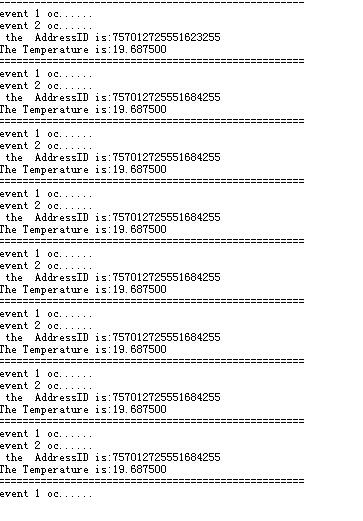
printf(" the AddressID is:") ;
for(k=0;k<8;k++) //字符不能直接输出,要按位输出
{
AddressID[k] = Read18B20();//读取地址
printf("%d", AddressID[k]);//输出地址
}
printf("\r\n") ; //换行
}
if(flag == 500) //判断flag是否等于500
{
printf("The Temperature is:%f\r\n",Read_T());//读取温度并输出
printf("===================================================\r\n");
}
}
}
#ifdef USE_FULL_ASSERT
/**
* @brief Reports the name of the source file and the source line number
* where the assert_param error has occurred.
* @param file: pointer to the source file name
* @param line: assert_param error line source number
* @retval None
*/
void assert_failed(uint8_t* file, uint32_t line)
{
/* User can add his own implementation to report the file name and line number,
ex: printf("Wrong parameters value: file %s on line %d\r\n", file, line) */
/* Infinite loop */
while (1)
{
}
}
#endif
/**
* @}
*/
/**
* @}
*/
#ifdef __GNUC__
/* With GCC/RAISONANCE, small printf (option LD Linker->Libraries->Small printf
set to 'Yes') calls __io_putchar() */
#define PUTCHAR_PROTOTYPE int __io_putchar(int ch)
#else
#define PUTCHAR_PROTOTYPE int fputc(int ch, FILE *f)
#endif /* __GNUC__ */
/**
* @brief Retargets the C library printf function to the USART.
* @param None
* @retval None
*/
PUTCHAR_PROTOTYPE
{
/* Place your implementation of fputc here */
/* e.g. write a character to the USART */
USART_SendData(EVAL_COM1, (uint8_t) ch);
/* Loop until the end of transmission */
while (USART_GetFlagStatus(EVAL_COM1, USART_FLAG_TC) == RESET)
{}
return ch;
}
#ifdef USE_FULL_ASSERT
/**
* @brief Reports the name of the source file and the source line number
* where the assert_param error has occurred.
* @param file: pointer to the source file name
* @param line: assert_param error line source number
* @retval None
*/
void assert_failed(uint8_t* file, uint32_t line)
{
/* User can add his own implementation to report the file name and line number,
ex: printf("Wrong parameters value: file %s on line %d\r\n", file, line) */
/* Infinite loop */
while (1)
{
}
}
#endif
回复
 我要赚赏金打赏帖 我要赚赏金打赏帖 |
|
|---|---|
| 【S32K3XX】FlexCAN 模块配置使用被打赏¥30元 | |
| 【S32K3XX】FlexCAN RAM 资源分配整理被打赏¥25元 | |
| 【S32K3XX】IPCF 适配核间中断处理被打赏¥21元 | |
| 【S32K3XX】IPCF 核间通讯模块UNMANAGED方式使用被打赏¥29元 | |
| 片外存储Flash使用方法(Arduino IDE环境)被打赏¥22元 | |
| 三分钟快速上手ESP-NOW(ArduinoIDE环境)被打赏¥23元 | |
| 【S32K3XX】LPSPI参数配置说明被打赏¥21元 | |
| 在WT9932C61-TINY上实现超声波测距被打赏¥22元 | |
| 基于WT9932C61-TINY的环境构建及OLED屏驱动测试被打赏¥20元 | |
| 【S32K3XX】Core-to-Core 中断使用被打赏¥21元 | |
 STM32
STM32 MCU
MCU 通讯及无线技术
 物联网技术
物联网技术 电子DIY
电子DIY 板卡试用
板卡试用 基础知识
基础知识 软件与操作系统
 我爱生活
我爱生活 小e食堂
小e食堂

