Abstract
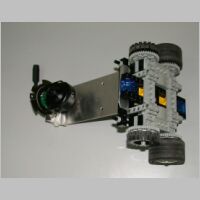
In this project a controllable Lego vehicle with an onboard camera was built, the visual data analyzed and the vehicle controlled by a PC navigating through several traffic signs in a playground that was set up for this purpose.
 |
 |
 |
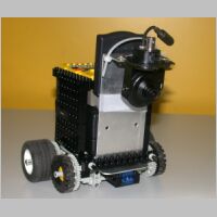
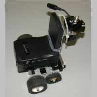
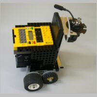
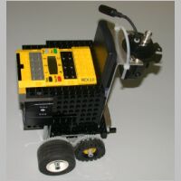
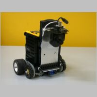
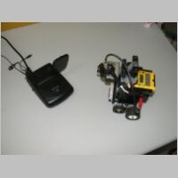
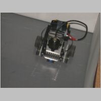
| Figure 1 The LEGO vehicle |
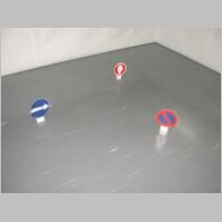
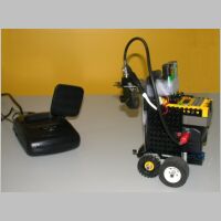
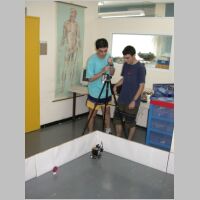
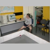
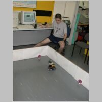
Figure 2 The playground used |
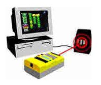
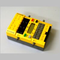
Figure 3 The PC link |
Introduction
The aim of the project was to build a system that helps navigate a vehicle by computer aided vision. In our work a vehicle with a camera attached to it navigated its way according to traffic signs that were placed in its way. Such a navigating system could be very useful in a real vehicle, e.g. in a warning system that alerts the driver if a traffic sign is recognized. One could think even of a self-driving vehicle hat doesn't need a driver behind its wheel at all. For humans, it is very easy and natural to recognize objects by sight. By just looking at an object we recognize it immediately without even thinking of it consciously. It seems that modern computers are still far away from the performance of the visual brain. In this work we concentrate in recognizing different traffic signs by means of color analysis. Computers, on the contrary, don't understand pictures it receives from a camera naturally. Very sophisticated methods must be used in order to recognize only quite simple visual tasks. In this work we concentrated in several certain traffic signs that can be separated easily by color analysis.
Tools & Environment
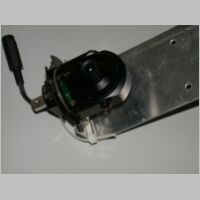
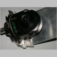
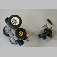
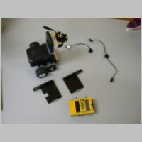
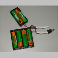
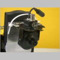
A LEGO Mindstorms Robotic Invention System set with a programmable controller (RCX), 4 wheels and 2 motors and some standard LEGO bricks were used for the vehicle. A miniature camera of type WATEC 207-CD was attached and battery powered and a RF Video Signal Transmitter-Receiver couple used (the Transmitter also attached to the vehicle and powered by battery pack). An infrared link built-in the RCX controller enabled communication with the Pentium 3 PC that hosted the controlling program. As software tool for sending commands from the PC to the RCX controller we used the Phantom ActiveX control published by LEGO fans on the Internet. A commercial software library named VideoOCX served us for capturing images from the camera through a VFW (Video for Windows) compatible PC video capture card of type Flyvideo 98 using the Visual Basic development environment (version 6.0). A 2.5 X 2.5 meter playground with gray ground and white walls and several paper-made traffic signs were used as the experiment environment.
Development
1. Building the vehicle
The Lego Mindstorms?Robot Invention System and the accessories mentioned above were used to build the controllable vehicle, the RCX loaded with a basic operation system (firmware) and a program written in Visual Basic that is capable of capturing pictures from the camera and send control commands to the RCX controller of the vehicle.
118.47 KB |
146.24 KB |
694.88 KB |
716.44 KB |
176.62 KB |
146.40 KB |
865.02 KB |
109.51 KB |
109.79 KB |
141.57 KB |
113.87 KB |
659.53 KB |
165.45 KB |
187.22 KB |
179.10 KB |
184.69 KB |
195.72 KB |
972.34 KB |
816.86 KB |
205.17 KB |
670.49 KB |
|
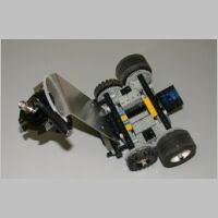
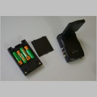
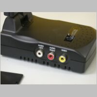
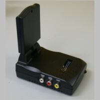
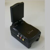
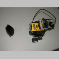
Figure 4 The equipment used
|
2. Image Processing
Locating the sign in the image
In this step the image frames captured from the camera were processed by our program. First the coordinates of a possible traffic sign were recognized. In order to do that, the HSV (Hue Saturation Value) color space was used. The image received from the camera is in RGB (Red, Green, Blue) format, where every pixel is a combination of the three colors. Using the HSV color space, it was possible to isolate the pixels that belong to the traffic sign in the picture according to the saturation level.
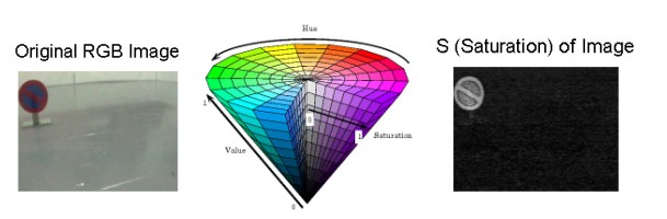 |
| Figure 5: Using the Saturation level to locate colored pixels in the image |
Identifying the Sign
In this step the pixels of high saturation were examined for their hue value to identify the color. As the background of the playing area was mainly gray level, no color was found besides the traffic signs, so that it was possible to distinguish the different signs by counting the colored pixels.
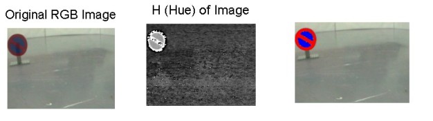 |
| Figure 6: Using the Hue value to identify the colors in the sign |
Estimate Distance
The relative number of pixels of each color was used to decide which traffic sign is recognized. The absolute number of the pixels was used in order to estimate the distance of the sign from the vehicle.
Control the vehicle
The information gathered from the visual data was used in order to decide on control commands for the vehicle:
Turn to right, turn to left or stop and turn vehicle OFF according to the sign.
3. Experiments
Several traffic signs were placed randomly in the play area and the vehicle run freely. Our computer program captured the image frames and sent control commands to the robot according to the wanted reaction to the identified traffic sign.
Results:
In our experiments, when one of the traffic signs were in the field of view of the camera and close enough to the vehicle - it was recognized correctly and the vehicle acted as expected, i.e. it turned right or left or stopped.
The reaction time of the computer to recognize one of the signs was found to be about 2 seconds.
796.46 KB |
359.72 KB |

757.35 KB |
240.61 KB |
891.42 KB |
305.21 KB |
|
Figure 7: Experimenting
|
Results and discussion
The slow reaction time forced us to limit the vehicle to a low speed in order for it to identify the signs in time before it crashes into them. It was found that the vehicle does not turn the same angle (e.g. 90 degrees for left or right turn) in each case. This is probably the fault of low precision of the LEGO motors and of non-unique friction of the ground. Another problem was found to be 'noises' in the background (e.g. a person walking through the play area). The image-processing algorithm that was used is based on the fact that the background is not colored (e.g. gray level only) so that the color of the signs could be distinguished clearly from the background. In case of other colored objects the algorithm fails.
The angle of the traffic signs as sees by the camera is important because of the way the vehicle measures its distance from the sign. The distance of the sign is calculated by counting the number of colored pixels, when the camera sees a traffic sign in different angles, it will not take this into account but calculate the distance as from frontal view.
Another problem could be that the vehicle may not identify dirty signs because the algorithm expects ideal signs: The saturation value may not be high enough where the dirt appears. This could be not very significant because if there is only a small part of the sign that does not have a high enough saturation value, the rest of the sign may have enough colored pixels for the recognition algorithm to succeed. Another way the dirt could affect is if the saturation value is high enough but the color value as found from the Hue value may be wrong.
The computer can't recognize objects in images as easy as we can and a special program is needed for it to recognize some things, but most of the programs can only work under some conditions. This is why the making of a program that navigates a robot in the cityscape is a very difficult job. In order for such a robot to work in the real landscapes every little detail should be considered, and an algorithm like the one that was done in that project, an algorithm that recognizes the signs by saturation and color will not be sufficient.
Conclusions
The aim of the project was to build a system that helps navigate a vehicle by computer aided vision.
Our results were reasonable with the assumptions that we move slowly and have a not colored quite unique background. In real world we cannot assume that of course, so this work can be only a starting point for a development of a smart vehicle controlling system or driving assistance system.
Problems like real-time processing, precision of the motor control and arbitrary background have to be taken care of. In addition our work solved the recognition problem only for 3 certain traffic signs. Many signs cannot be recognized by our method as they are distinguished not only by color but also by shape.
The traffic sign recognition algorithm that was used in this project could not be used on a real car, because it only works in optimal conditions where everything except of the traffic signs is white, but after improving the image processing algorithm and real-time running performance a navigating system such as developed in this work could be very useful in a real vehicle, e.g. in a warning system that alerts the driver if a traffic sign is recognized. One could think even of a self-driving vehicle hat doesn't need a driver behind its wheel at all.
References
1. MATLAB documentation.
2. http://members.cox.net/pbrick-alpha/Phantom.htm (Phantom ActiveX control for LEGO Mindstorms).
3. http://www.videoocx.de
4. http://www.legomindstorms.com/
Acknowledgments
We'd like to thank our supervisors Johanan Erez and Ina Krinsky and the lab assistant Dror Ouzana.
Our thanks to the Electrical Engineering Faculty that kindly hosted us in their department and to Orth Highschools management for the scholarship that enabled this work.
We would also like to express our special gratitude to the Ollendorff Research Center for supporting this project with equipment.
|

 我要赚赏金
我要赚赏金 STM32
STM32 MCU
MCU 通讯及无线技术
 物联网技术
物联网技术 电子DIY
电子DIY 板卡试用
板卡试用 基础知识
基础知识 软件与操作系统
 我爱生活
我爱生活 小e食堂
小e食堂

