
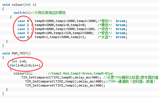
case i 的值只有0到4 为啥要用for自加到6捏?
现在写的是用电阻变化的大小来控制PWM的变化
只是白色亮度大小的变化
延时的时候会出现颜色的变化
改进ing
#include "stm32f10x.h"
#include "stm32_eval.h"
#include
#define VREF 3.3
int temp0,temp1,temp2;
/*延时函数 微秒*/
void delay_us(u32 n)
{
u8 j;
while(n--)
for(j=0;j<10;j++);
}
/*延时函数 毫秒*/
void delay_ms(u32 n)
{
while(n--)
delay_us(1000);
}
GPIO_InitTypeDef GPIO_InitStructure;
USART_InitTypeDef USART_InitStructure;
USART_ClockInitTypeDef USART_ClockInitStructure;
void RCC_Configuration(void)
{
SystemInit();
RCC_APB2PeriphClockCmd(RCC_APB2Periph_GPIOD|RCC_APB2Periph_AFIO, ENABLE);
GPIO_PinRemapConfig(GPIO_Remap_SWJ_JTAGDisable,ENABLE);//disable JTAG
RCC_APB2PeriphClockCmd(RCC_APB2Periph_GPIOD|RCC_APB2Periph_AFIO, ENABLE);
GPIO_PinRemapConfig(GPIO_Remap_SWJ_JTAGDisable,ENABLE);//disable JTAG
GPIO_InitStructure.GPIO_Pin = GPIO_Pin_2;
GPIO_InitStructure.GPIO_Speed = GPIO_Speed_50MHz;
GPIO_InitStructure.GPIO_Mode = GPIO_Mode_Out_PP;
GPIO_Init(GPIOD, &GPIO_InitStructure);
GPIO_ResetBits(GPIOD,GPIO_Pin_2);
RCC_APB2PeriphClockCmd(RCC_APB2Periph_GPIOC|RCC_APB2Periph_AFIO, ENABLE);
GPIO_PinRemapConfig(GPIO_Remap_SWJ_JTAGDisable,ENABLE);//disable JTAG
GPIO_InitStructure.GPIO_Pin = GPIO_Pin_0|GPIO_Pin_1|GPIO_Pin_2|GPIO_Pin_3|GPIO_Pin_4|GPIO_Pin_5|GPIO_Pin_6|GPIO_Pin_7;
GPIO_InitStructure.GPIO_Speed = GPIO_Speed_50MHz;
GPIO_InitStructure.GPIO_Mode = GPIO_Mode_Out_PP;
GPIO_Init(GPIOC, &GPIO_InitStructure);
GPIO_SetBits(GPIOC,GPIO_Pin_0|GPIO_Pin_1|GPIO_Pin_2|GPIO_Pin_3|GPIO_Pin_4|GPIO_Pin_5|GPIO_Pin_6|GPIO_Pin_7);
RCC_APB1PeriphClockCmd(RCC_APB1Periph_TIM2, ENABLE);
}
void USART_int(long BaudRate)
{
RCC_APB2PeriphClockCmd(RCC_APB2Periph_GPIOA|RCC_APB2Periph_USART1,ENABLE);
GPIO_InitStructure.GPIO_Pin = GPIO_Pin_9;
GPIO_InitStructure.GPIO_Speed = GPIO_Speed_10MHz;
GPIO_InitStructure.GPIO_Mode = GPIO_Mode_AF_PP;
GPIO_Init(GPIOA, &GPIO_InitStructure);
/* PA10 USART1_Rx */
GPIO_InitStructure.GPIO_Pin = GPIO_Pin_10;
GPIO_InitStructure.GPIO_Mode = GPIO_Mode_IN_FLOATING;
GPIO_Init(GPIOA, &GPIO_InitStructure);
USART_InitStructure.USART_BaudRate = BaudRate;//??????
USART_InitStructure.USART_WordLength = USART_WordLength_8b;//???????8bit
USART_InitStructure.USART_StopBits = USART_StopBits_1;//????1
USART_InitStructure.USART_Parity = USART_Parity_No;//????
USART_InitStructure.USART_HardwareFlowControl = USART_HardwareFlowControl_None;//??????none
USART_InitStructure.USART_Mode = USART_Mode_Rx | USART_Mode_Tx;//??????????
USART_ClockInitStructure.USART_Clock = USART_Clock_Disable;
USART_ClockInitStructure.USART_CPOL = USART_CPOL_Low;
USART_ClockInitStructure.USART_CPHA = USART_CPHA_2Edge;
USART_ClockInitStructure.USART_LastBit = USART_LastBit_Disable;
USART_ClockInit(USART1, &USART_ClockInitStructure);
USART_Init(USART1, &USART_InitStructure);
USART_Cmd(USART1, ENABLE);
USART_ITConfig(USART1, USART_IT_RXNE, ENABLE);
USART_Cmd(USART1, ENABLE);
}
void GPIO_INIT()
{
RCC_APB2PeriphClockCmd(RCC_APB2Periph_GPIOC, ENABLE); //RCC_APB2Periph_GPIOB 开启GPIOB的时钟 ENABLE\DISABLE 打开or关闭
GPIO_InitStructure.GPIO_Pin = GPIO_Pin_8|GPIO_Pin_9|GPIO_Pin_10;//按键使用PC8-10
GPIO_InitStructure.GPIO_Speed = GPIO_Speed_50MHz; //速度:配置晶振
GPIO_InitStructure.GPIO_Mode = GPIO_Mode_IN_FLOATING; //模式:Out_PP推挽输出,可做输出,输入 !!!
GPIO_Init(GPIOC, &GPIO_InitStructure);
}
void ADC_CONFIG(){
ADC_InitTypeDef ADC_InitStructure;
#if defined (STM32F10X_LD_VL) || defined (STM32F10X_MD_VL) || defined (STM32F10X_HD_VL)
/* ADCCLK = PCLK2/2 */
RCC_ADCCLKConfig(RCC_PCLK2_Div2);
#else
/* ADCCLK = PCLK2/4 */
RCC_ADCCLKConfig(RCC_PCLK2_Div4);
#endif
ADC_DeInit(ADC1);
/* Enable ADC1 and GPIOC clock */
RCC_APB2PeriphClockCmd(RCC_APB2Periph_ADC1 | RCC_APB2Periph_GPIOB, ENABLE);
/* Configure PB0 (ADC Channel14) as analog input -------------------------*/
GPIO_InitStructure.GPIO_Pin = GPIO_Pin_0;
GPIO_InitStructure.GPIO_Mode = GPIO_Mode_AIN;
GPIO_Init(GPIOB, &GPIO_InitStructure);
/* ADC1 configuration ------------------------------------------------------*/
ADC_InitStructure.ADC_Mode = ADC_Mode_Independent;
ADC_InitStructure.ADC_ScanConvMode = ENABLE;
ADC_InitStructure.ADC_ContinuousConvMode = ENABLE;
ADC_InitStructure.ADC_ExternalTrigConv = ADC_ExternalTrigConv_None;
ADC_InitStructure.ADC_DataAlign = ADC_DataAlign_Right;
ADC_InitStructure.ADC_NbrOfChannel = 1;
ADC_Init(ADC1, &ADC_InitStructure);
/* Enable ADC1 DMA */
ADC_DMACmd(ADC1, ENABLE);
/* Enable ADC1 */
ADC_Cmd(ADC1, ENABLE);
}
int Get_ADC(){
/* ADC1 regular channel configuration */
ADC_RegularChannelConfig(ADC1, ADC_Channel_8, 1, ADC_SampleTime_55Cycles5);
/* Enable ADC1 reset calibration register */
ADC_ResetCalibration(ADC1);
/* Check the end of ADC1 reset calibration register */
while(ADC_GetResetCalibrationStatus(ADC1));
/* Start ADC1 calibration */
ADC_StartCalibration(ADC1);
/* Check the end of ADC1 calibration */
while(ADC_GetCalibrationStatus(ADC1));
/* Start ADC1 Software Conversion */
ADC_SoftwareStartConvCmd(ADC1, ENABLE);
return ADC_GetConversionValue(ADC1);
}
void PWM_Config()
{uint16_t PrescalerValue = 0;
TIM_TimeBaseInitTypeDef TIM_TimeBaseStructure;//定义结构体
TIM_OCInitTypeDef TIM_OCInitStructure;
RCC_APB1PeriphClockCmd(RCC_APB1Periph_TIM2, ENABLE);//打开TIM2,TIM2挂在AP1上
RCC_APB2PeriphClockCmd(RCC_APB2Periph_AFIO , ENABLE);//一、开启功能复用
GPIO_InitStructure.GPIO_Pin = GPIO_Pin_1|GPIO_Pin_2|GPIO_Pin_3;
GPIO_InitStructure.GPIO_Mode = GPIO_Mode_AF_PP;//所需的3个管脚,复用输出
GPIO_InitStructure.GPIO_Speed = GPIO_Speed_50MHz;
GPIO_Init(GPIOA, &GPIO_InitStructure);
// GPIO_SetBits(GPIOA,GPIO_Pin_1|GPIO_Pin_2|GPIO_Pin_3);
// delay_ms(20);
TIM_Cmd(TIM2, ENABLE);
PrescalerValue = (uint16_t) (SystemCoreClock / 24000000) - 1;//二、配置TIM2
/* Time base configuration */
TIM_TimeBaseStructure.TIM_Period = 0x0FFE;
TIM_TimeBaseStructure.TIM_Prescaler = PrescalerValue;
TIM_TimeBaseStructure.TIM_ClockDivision = 0;
TIM_TimeBaseStructure.TIM_CounterMode = TIM_CounterMode_Up;
TIM_TimeBaseInit(TIM2, &TIM_TimeBaseStructure);
TIM_OCInitStructure.TIM_OCMode = TIM_OCMode_PWM1;//三、脉冲宽度调制模式1
TIM_OCInitStructure.TIM_OCPolarity = TIM_OCPolarity_High;
/* PWM1 Mode configuration: Channel2 *///四、
TIM_OCInitStructure.TIM_OutputState = TIM_OutputState_Enable;//选择输出比较状态
TIM_OCInitStructure.TIM_Pulse = 0xFFFF;//IM_Pulse-设置了待装入捕获比较寄存器的脉冲值,取值在0x0000-0xFFFF之间
TIM_OC2Init(TIM2, &TIM_OCInitStructure);
/* PWM1 Mode configuration: Channel3 */
TIM_OCInitStructure.TIM_OutputState = TIM_OutputState_Enable;
TIM_OCInitStructure.TIM_Pulse = 0xFFFF;//0x0000最亮,0xFFFF熄灭
TIM_OC3Init(TIM2, &TIM_OCInitStructure);
/* PWM1 Mode configuration: Channel4 */
TIM_OCInitStructure.TIM_OutputState = TIM_OutputState_Enable;
TIM_OCInitStructure.TIM_Pulse = 0xFFFF;
TIM_OC4Init(TIM2, &TIM_OCInitStructure);
TIM_ARRPreloadConfig(TIM2, ENABLE);//reload-重新装载初始值
}
//void RGB(int a)
//{
//// int VCC;
//// VCC=a;
// //temp1-Red,temp2-Green,temp0-Blue
// if(!GPIO_ReadInputDataBit(GPIOC,GPIO_Pin_9)) //判断按键是否被按下
// {
// delay_ms(50); //延时去抖
// if(!GPIO_ReadInputDataBit(GPIOC,GPIO_Pin_9)) //判断按键是否被按下 假如端口PC8为低电平
// {
// printf(" !!!!!!!!!!!!!!!!!!!!!\r\n");
// //GPIO_ResetBits(GPIOA,GPIO_Pin_1|GPIO_Pin_2|GPIO_Pin_3);
// TIM_SetCompare2(TIM2,a);delay_ms(100); //设置TIM2捕获比较器2寄存器的值
// TIM_SetCompare3(TIM2,a);delay_ms(100);//TIM——通道数(定时器,数值)
// TIM_SetCompare4(TIM2,a);delay_ms(100);
// }
// }
//}
int main(void)
{
float Volt=0.00;
int ADValue = 0;
RCC_Configuration();
USART_int(115200);//设置波特率
GPIO_INIT();
ADC_CONFIG();
printf(" config done...\r\n");
Get_ADC();
delay_ms(1000);
PWM_Config();
delay_ms(1000);
while(1)
{
ADValue = Get_ADC();
// RGB(ADValue);
Volt = VREF*ADValue/4095;//实际电压
printf("===============================\r\n");
printf("The ADC value is:%d\r\n",ADValue);
printf("The Volt is:%f V\r\n",Volt);
delay_ms(500);
// if(!GPIO_ReadInputDataBit(GPIOC,GPIO_Pin_9)) //判断按键是否被按下
// {
// delay_ms(50); //延时去抖
// if(!GPIO_ReadInputDataBit(GPIOC,GPIO_Pin_9)) //判断按键是否被按下 假如端口PC8为低电平
// {
TIM_SetCompare2(TIM2,ADValue);delay_ms(100); //设置TIM2捕获比较器2寄存器的值
TIM_SetCompare3(TIM2,ADValue);delay_ms(100);//TIM——通道数(定时器,数值)
TIM_SetCompare4(TIM2,ADValue);delay_ms(100);
// }
// }
}
}
#ifdef USE_FULL_ASSERT
void assert_failed(uint8_t* file, uint32_t line)
{
while (1)
{
}
}
#endif
#ifdef __GNUC__
#define PUTCHAR_PROTOTYPE int __io_putchar(int ch)
#else
#define PUTCHAR_PROTOTYPE int fputc(int ch, FILE *f)
#endif /* __GNUC__ */
PUTCHAR_PROTOTYPE
{
USART_SendData(EVAL_COM1, (uint8_t) ch);
while (USART_GetFlagStatus(EVAL_COM1, USART_FLAG_TC) == RESET)
{}
return ch;
}
#ifdef USE_FULL_ASSERT
void assert_failed(uint8_t* file, uint32_t line)
{
while (1)
{
}
}
#endif
IIC记上电次数~
#include "stm32f10x.h"
#include "stm32_eval.h"
#include "STM32_I2C.h"
#include <stdio.h>

GPIO_InitTypeDef   GPIO_InitStructure;
USART_InitTypeDef USART_InitStructure;
USART_ClockInitTypeDef USART_ClockInitStructure;
EXTI_InitTypeDef   EXTI_InitStructure;
NVIC_InitTypeDef   NVIC_InitStructure;
unsigned char i;
void EXTIkeyS1_Config(void);

/*delay_us*/
void delay_us(u32 n)
{
    u8 j;
    while(n--)
    for(j=0;j<10;j++);
}
/*delay_ms*/

void  delay_ms(u32 n)
{
    while(n--)
    delay_us(1000);
}

void RCC_Configuration(void)
{
  RCC_DeInit();
  RCC_HSICmd(ENABLE);
  while(RCC_GetFlagStatus(RCC_FLAG_HSIRDY) == RESET);
  RCC_SYSCLKConfig(RCC_SYSCLKSource_HSI);
  RCC_HSEConfig(RCC_HSE_OFF);
  RCC_LSEConfig(RCC_LSE_OFF);
  RCC_PLLConfig(RCC_PLLSource_HSI_Div2,RCC_PLLMul_9); //  72HMz
  RCC_PLLCmd(ENABLE);
  while(RCC_GetFlagStatus(RCC_FLAG_PLLRDY) == RESET);
  RCC_ADCCLKConfig(RCC_PCLK2_Div4);
  RCC_PCLK2Config(RCC_HCLK_Div1);
  RCC_PCLK1Config(RCC_HCLK_Div2);
  RCC_HCLKConfig(RCC_SYSCLK_Div1);
  RCC_SYSCLKConfig(RCC_SYSCLKSource_PLLCLK);
  while(RCC_GetSYSCLKSource() != 0x08);
    //SystemInit();
    RCC_APB2PeriphClockCmd(RCC_APB2Periph_GPIOD|RCC_APB2Periph_AFIO, ENABLE);
  GPIO_PinRemapConfig(GPIO_Remap_SWJ_JTAGDisable,ENABLE);//disable JTAG
  RCC_APB2PeriphClockCmd(RCC_APB2Periph_GPIOD|RCC_APB2Periph_AFIO, ENABLE);
  GPIO_PinRemapConfig(GPIO_Remap_SWJ_JTAGDisable,ENABLE);//disable JTAG
  GPIO_InitStructure.GPIO_Pin = GPIO_Pin_2;
  GPIO_InitStructure.GPIO_Speed = GPIO_Speed_50MHz;
  GPIO_InitStructure.GPIO_Mode = GPIO_Mode_Out_PP;
  GPIO_Init(GPIOD, &GPIO_InitStructure);
    GPIO_ResetBits(GPIOD,GPIO_Pin_2);
    RCC_APB2PeriphClockCmd(RCC_APB2Periph_GPIOC|RCC_APB2Periph_AFIO, ENABLE);
  GPIO_PinRemapConfig(GPIO_Remap_SWJ_JTAGDisable,ENABLE);//disable JTAG
  GPIO_InitStructure.GPIO_Pin = GPIO_Pin_0|GPIO_Pin_1|GPIO_Pin_2|GPIO_Pin_3|GPIO_Pin_4|GPIO_Pin_5|GPIO_Pin_6|GPIO_Pin_7;
  GPIO_InitStructure.GPIO_Speed = GPIO_Speed_50MHz;
  GPIO_InitStructure.GPIO_Mode = GPIO_Mode_Out_PP;
  GPIO_Init(GPIOC, &GPIO_InitStructure);
    GPIO_SetBits(GPIOC,GPIO_Pin_0|GPIO_Pin_1|GPIO_Pin_2|GPIO_Pin_3|GPIO_Pin_4|GPIO_Pin_5|GPIO_Pin_6|GPIO_Pin_7);
      RCC_APB1PeriphClockCmd(RCC_APB1Periph_TIM2, ENABLE);
}

void USART_int(long BaudRate)
{
      RCC_APB2PeriphClockCmd(RCC_APB2Periph_GPIOA|RCC_APB2Periph_USART1,ENABLE);
    GPIO_InitStructure.GPIO_Pin = GPIO_Pin_9;
    GPIO_InitStructure.GPIO_Speed = GPIO_Speed_50MHz;
    GPIO_InitStructure.GPIO_Mode = GPIO_Mode_AF_PP;
    GPIO_Init(GPIOA, &GPIO_InitStructure);
    /* PA10 USART1_Rx  */
    GPIO_InitStructure.GPIO_Pin = GPIO_Pin_10;
    GPIO_InitStructure.GPIO_Mode = GPIO_Mode_IN_FLOATING;
    GPIO_Init(GPIOA, &GPIO_InitStructure);
  /* USARTx configured as follow:
        - BaudRate = 115200 baud
        - Word Length = 8 Bits
        - One Stop Bit
        - No parity
        - Hardware flow control disabled (RTS and CTS signals)
        - Receive and transmit enabled
  */
  USART_InitStructure.USART_BaudRate = BaudRate;//??????
  USART_InitStructure.USART_WordLength = USART_WordLength_8b;//???????8bit
  USART_InitStructure.USART_StopBits = USART_StopBits_1;//????1
  USART_InitStructure.USART_Parity = USART_Parity_No;//????
  USART_InitStructure.USART_HardwareFlowControl = USART_HardwareFlowControl_None;//??????none
  USART_InitStructure.USART_Mode = USART_Mode_Rx | USART_Mode_Tx;//??????????
    USART_ClockInitStructure.USART_Clock = USART_Clock_Disable;
    USART_ClockInitStructure.USART_CPOL = USART_CPOL_Low;
    USART_ClockInitStructure.USART_CPHA = USART_CPHA_2Edge;
    USART_ClockInitStructure.USART_LastBit = USART_LastBit_Disable;
    USART_ClockInit(USART1, &USART_ClockInitStructure);
  USART_Init(USART1, &USART_InitStructure);
  USART_Cmd(USART1, ENABLE);
    USART_ITConfig(USART1, USART_IT_RXNE, ENABLE);
  USART_Cmd(USART1, ENABLE);
      /* Configure four bit for preemption priority */
  NVIC_PriorityGroupConfig(NVIC_PriorityGroup_4);
  /* Enable the USART1 Interrupt */
  NVIC_InitStructure.NVIC_IRQChannel = USART1_IRQn; //
  NVIC_InitStructure.NVIC_IRQChannelPreemptionPriority = 15;
  NVIC_InitStructure.NVIC_IRQChannelCmd = ENABLE;
  NVIC_Init(&NVIC_InitStructure);
}

void IIc2_Init(void)
{
        GPIO_InitTypeDef GPIO_InitStructure;
        I2C_InitTypeDef I2C_InitStructure;

        RCC_APB2PeriphClockCmd(RCC_APB2Periph_GPIOB, ENABLE);
        RCC_APB1PeriphClockCmd(RCC_APB1Periph_I2C2, ENABLE);
        //PB6-I2C2_SCL PB7-I2C2_SDA PB10-I2C2_SCL PB11-I2C2_SDA
        /* Configure IO connected to IIC*********************/
        GPIO_InitStructure.GPIO_Pin =  GPIO_Pin_10 | GPIO_Pin_11;
        GPIO_InitStructure.GPIO_Speed = GPIO_Speed_50MHz;
        GPIO_InitStructure.GPIO_Mode = GPIO_Mode_AF_OD;
        GPIO_Init(GPIOB, &GPIO_InitStructure);

        I2C_InitStructure.I2C_Mode = I2C_Mode_I2C;
        I2C_InitStructure.I2C_DutyCycle = I2C_DutyCycle_2;
        I2C_InitStructure.I2C_OwnAddress1 = 0xA0;
        I2C_InitStructure.I2C_Ack = I2C_Ack_Enable;
        I2C_InitStructure.I2C_AcknowledgedAddress = I2C_AcknowledgedAddress_7bit;
        I2C_InitStructure.I2C_ClockSpeed = 400000;
        I2C_Cmd(I2C2, ENABLE);
        I2C_Init(I2C2, &I2C_InitStructure);
        I2C_AcknowledgeConfig(I2C2, ENABLE);
}

void I2C2_WriteByte(unsigned char id,unsigned char write_address,unsigned char byte)
{
        while(I2C_GetFlagStatus(I2C2, I2C_FLAG_BUSY));
        I2C_GenerateSTART(I2C2,ENABLE);
        while(!I2C_CheckEvent(I2C2, I2C_EVENT_MASTER_MODE_SELECT));
        I2C_Send7bitAddress(I2C2,id,I2C_Direction_Transmitter);
        while(!I2C_CheckEvent(I2C2, I2C_EVENT_MASTER_TRANSMITTER_MODE_SELECTED));
        I2C_SendData(I2C2, write_address);
        while(!I2C_CheckEvent(I2C2, I2C_EVENT_MASTER_BYTE_TRANSMITTED));
        I2C_SendData(I2C2, byte);
        while(!I2C_CheckEvent(I2C2, I2C_EVENT_MASTER_BYTE_TRANSMITTED));
        I2C_GenerateSTOP(I2C2, ENABLE);
        do
        {
           /* Send START condition */
           I2C_GenerateSTART(I2C2, ENABLE);
          /* Read I2C2 SR1 register */
            /* Send EEPROM address for write */
            I2C_Send7bitAddress(I2C2, 0xA0, I2C_Direction_Transmitter);
        }while(!(I2C_ReadRegister(I2C2, I2C_Register_SR1) & 0x0002));

        /* Clear AF flag */
        I2C_ClearFlag(I2C2, I2C_FLAG_AF);
        /* STOP condition */
        I2C_GenerateSTOP(I2C2, ENABLE);
}

unsigned char I2C2_ReadByte(unsigned char  id, unsigned char read_address)
{
     unsigned char temp;
     while(I2C_GetFlagStatus(I2C2, I2C_FLAG_BUSY)){}
     I2C_GenerateSTART(I2C2, ENABLE);
     while(!I2C_CheckEvent(I2C2, I2C_EVENT_MASTER_MODE_SELECT));
     I2C_Send7bitAddress(I2C2, id, I2C_Direction_Transmitter);
     while(!I2C_CheckEvent(I2C2, I2C_EVENT_MASTER_TRANSMITTER_MODE_SELECTED));
     I2C_Cmd(I2C2, ENABLE);
     I2C_SendData(I2C2, read_address);
     while(!I2C_CheckEvent(I2C2, I2C_EVENT_MASTER_BYTE_TRANSMITTED));
     I2C_GenerateSTART(I2C2, ENABLE);
     while(!I2C_CheckEvent(I2C2, I2C_EVENT_MASTER_MODE_SELECT));
     I2C_Send7bitAddress(I2C2, id, I2C_Direction_Receiver);
     while(!I2C_CheckEvent(I2C2, I2C_EVENT_MASTER_RECEIVER_MODE_SELECTED));
    I2C_AcknowledgeConfig(I2C2, DISABLE);
    I2C_GenerateSTOP(I2C2, ENABLE);
    while(!(I2C_CheckEvent(I2C2, I2C_EVENT_MASTER_BYTE_RECEIVED)));
    temp = I2C_ReceiveData(I2C2);
    I2C_AcknowledgeConfig(I2C2, ENABLE);
     return temp;
}

int main(void)
{
  RCC_Configuration();
  EXTIkeyS1_Config();
  USART_int(115200);
  IIc2_Init();
    printf(" config done...\r\n");
    i = I2C2_ReadByte(0xA0,0);//向0x00读取数据
    printf("从地址0x00读出数据 :%d\r\n",i);
    i++;
    I2C2_WriteByte(0xA0,0,i);//向0x00写入数据
    printf("向地址0x00写入数据 :%d\r\n",i);
    while(1)
    {
     delay_ms(2000);
     printf(" 上电次数为%d\r\n",i);
    }
}
void EXTIkeyS1_Config(void)//S1 PC8
{
  /* Enable GPIOA clock */
  RCC_APB2PeriphClockCmd(RCC_APB2Periph_GPIOC, ENABLE);
  /* Configure PA.00 pin as input floating */
  GPIO_InitStructure.GPIO_Pin = GPIO_Pin_8;//PC8 S1
  GPIO_InitStructure.GPIO_Mode = GPIO_Mode_IN_FLOATING;
  GPIO_Init(GPIOC, &GPIO_InitStructure);
  /* Enable AFIO clock */
  RCC_APB2PeriphClockCmd(RCC_APB2Periph_AFIO, ENABLE);
  GPIO_EXTILineConfig(GPIO_PortSourceGPIOC, GPIO_PinSource8);
  EXTI_InitStructure.EXTI_Line = EXTI_Line8;
  EXTI_InitStructure.EXTI_Mode = EXTI_Mode_Interrupt;
  EXTI_InitStructure.EXTI_Trigger = EXTI_Trigger_Falling;
  EXTI_InitStructure.EXTI_LineCmd = ENABLE;
  EXTI_Init(&EXTI_InitStructure);
  NVIC_InitStructure.NVIC_IRQChannel = EXTI9_5_IRQn;
  NVIC_InitStructure.NVIC_IRQChannelPreemptionPriority = 0x0F;
  NVIC_InitStructure.NVIC_IRQChannelSubPriority = 0x0F;
  NVIC_InitStructure.NVIC_IRQChannelCmd = ENABLE;
  NVIC_Init(&NVIC_InitStructure);
}
void EXTI9_5_IRQHandler(void)
{
  if(EXTI_GetITStatus(EXTI_Line8) != RESET)
  {
        i=0;
        I2C2_WriteByte(0xA0,0,0);
        printf(" 上电次数为%d\r\n",i);
    /* Clear the  EXTI line 8 pending bit */
    EXTI_ClearITPendingBit(EXTI_Line8);
  }
}

#ifdef  USE_FULL_ASSERT

void assert_failed(uint8_t* file, uint32_t line)
{
  while (1)
  {
  }
}

#endif

#ifdef __GNUC__

  #define PUTCHAR_PROTOTYPE int __io_putchar(int ch)
#else
  #define PUTCHAR_PROTOTYPE int fputc(int ch, FILE *f)
#endif /* __GNUC__ */


PUTCHAR_PROTOTYPE
{

  USART_SendData(EVAL_COM1, (uint8_t) ch);
  while (USART_GetFlagStatus(EVAL_COM1, USART_FLAG_TC) == RESET)
  {}

  return ch;
}

#ifdef  USE_FULL_ASSERT

void assert_failed(uint8_t* file, uint32_t line)
{
  while (1)
  {
  }
}

#endif
isp
#include "stm32f10x.h"
#include "stm32_eval.h"
#include <stdio.h>
#include "spi_flash.h"
//#define VREF 3.3

/*延时函数 微秒*/
void delay_us(u32 n)
{
    u8 j;
    while(n--)
    for(j=0;j<10;j++);
}
/*延时函数 毫秒*/

void  delay_ms(u32 n)
{
   while(n--)
    delay_us(1000);
}

#define TxBufferSize1   (countof(TxBuffer1) - 1)
#define RxBufferSize1   (countof(TxBuffer1) - 1)
#define countof(a)      (sizeof(a) / sizeof(*(a)))
#define  BufferSize (countof(Tx_Buffer)-1)
typedef enum { FAILED = 0, PASSED = !FAILED} TestStatus;
#define  FLASH_WriteAddress     0x00000
#define  FLASH_ReadAddress      FLASH_WriteAddress
#define  FLASH_SectorToErase    FLASH_WriteAddress
#define  sFLASH_ID              0xEF3015     //W25X16的地址,不可以改的

#define buff_size  16;
char rx_buff[],rx_buff_count=0;

uint8_t Tx_Buffer[] = "欢迎使用STM32掌上实验室\r\n                www.zsxy.gxnu.edu.cn";
uint8_t Rx_Buffer[BufferSize];

__IO uint32_t DeviceID = 0;
__IO uint32_t FlashID = 0;
__IO TestStatus TransferStatus1 = FAILED;

void Delay(__IO uint32_t nCount);
TestStatus Buffercmp(uint8_t* pBuffer1, uint8_t* pBuffer2, uint16_t BufferLength);

GPIO_InitTypeDef   GPIO_InitStructure;
USART_InitTypeDef USART_InitStructure;
USART_ClockInitTypeDef USART_ClockInitStructure;

void RCC_Configuration(void)
{
  RCC_DeInit();

  RCC_HSICmd(ENABLE);
  while(RCC_GetFlagStatus(RCC_FLAG_HSIRDY) == RESET);

  RCC_SYSCLKConfig(RCC_SYSCLKSource_HSI);

  RCC_HSEConfig(RCC_HSE_OFF);
  RCC_LSEConfig(RCC_LSE_OFF);
  RCC_PLLConfig(RCC_PLLSource_HSI_Div2,RCC_PLLMul_9); //  72HMz
  RCC_PLLCmd(ENABLE);
  while(RCC_GetFlagStatus(RCC_FLAG_PLLRDY) == RESET);
  RCC_ADCCLKConfig(RCC_PCLK2_Div4);
  RCC_PCLK2Config(RCC_HCLK_Div1);
  RCC_PCLK1Config(RCC_HCLK_Div2);
  RCC_HCLKConfig(RCC_SYSCLK_Div1);
  RCC_SYSCLKConfig(RCC_SYSCLKSource_PLLCLK);
  while(RCC_GetSYSCLKSource() != 0x08);

	RCC_APB2PeriphClockCmd(RCC_APB2Periph_GPIOD|RCC_APB2Periph_AFIO, ENABLE);
  GPIO_PinRemapConfig(GPIO_Remap_SWJ_JTAGDisable,ENABLE);//disable JTAG
  RCC_APB2PeriphClockCmd(RCC_APB2Periph_GPIOD|RCC_APB2Periph_AFIO, ENABLE);
  GPIO_PinRemapConfig(GPIO_Remap_SWJ_JTAGDisable,ENABLE);//disable JTAG
  GPIO_InitStructure.GPIO_Pin = GPIO_Pin_2;
  GPIO_InitStructure.GPIO_Speed = GPIO_Speed_50MHz;
  GPIO_InitStructure.GPIO_Mode = GPIO_Mode_Out_PP;
  GPIO_Init(GPIOD, &GPIO_InitStructure);
	GPIO_ResetBits(GPIOD,GPIO_Pin_2);
	RCC_APB2PeriphClockCmd(RCC_APB2Periph_GPIOC|RCC_APB2Periph_AFIO, ENABLE);
  GPIO_PinRemapConfig(GPIO_Remap_SWJ_JTAGDisable,ENABLE);//disable JTAG
  GPIO_InitStructure.GPIO_Pin = GPIO_Pin_0|GPIO_Pin_1|GPIO_Pin_2|GPIO_Pin_3|GPIO_Pin_4|GPIO_Pin_5|GPIO_Pin_6|GPIO_Pin_7;
  GPIO_InitStructure.GPIO_Speed = GPIO_Speed_50MHz;
  GPIO_InitStructure.GPIO_Mode = GPIO_Mode_Out_PP;
  GPIO_Init(GPIOC, &GPIO_InitStructure);
	GPIO_SetBits(GPIOC,GPIO_Pin_0|GPIO_Pin_1|GPIO_Pin_2|GPIO_Pin_3|GPIO_Pin_4|GPIO_Pin_5|GPIO_Pin_6|GPIO_Pin_7);
	RCC_APB1PeriphClockCmd(RCC_APB1Periph_TIM2, ENABLE);
}

void USART_int(long BaudRate)
{
	  RCC_APB2PeriphClockCmd(RCC_APB2Periph_GPIOA|RCC_APB2Periph_USART1,ENABLE);
    GPIO_InitStructure.GPIO_Pin = GPIO_Pin_9;
    GPIO_InitStructure.GPIO_Speed = GPIO_Speed_50MHz;
    GPIO_InitStructure.GPIO_Mode = GPIO_Mode_AF_PP;
    GPIO_Init(GPIOA, &GPIO_InitStructure);
    /* PA10 USART1_Rx  */
    GPIO_InitStructure.GPIO_Pin = GPIO_Pin_10;
    GPIO_InitStructure.GPIO_Mode = GPIO_Mode_IN_FLOATING;
    GPIO_Init(GPIOA, &GPIO_InitStructure);

		USART_InitStructure.USART_BaudRate = BaudRate;//??????
		USART_InitStructure.USART_WordLength = USART_WordLength_8b;//???????8bit
		USART_InitStructure.USART_StopBits = USART_StopBits_1;//????1
		USART_InitStructure.USART_Parity = USART_Parity_No;//????
		USART_InitStructure.USART_HardwareFlowControl = USART_HardwareFlowControl_None;//??????none
		USART_InitStructure.USART_Mode = USART_Mode_Rx | USART_Mode_Tx;//??????????
		USART_ClockInitStructure.USART_Clock = USART_Clock_Disable;
    USART_ClockInitStructure.USART_CPOL = USART_CPOL_Low;
    USART_ClockInitStructure.USART_CPHA = USART_CPHA_2Edge;
    USART_ClockInitStructure.USART_LastBit = USART_LastBit_Disable;
    USART_ClockInit(USART1, &USART_ClockInitStructure);
		USART_Init(USART1, &USART_InitStructure);
		USART_Cmd(USART1, ENABLE);
		USART_ITConfig(USART1, USART_IT_RXNE, ENABLE);
    USART_Cmd(USART1, ENABLE);
}

TestStatus Buffercmp(uint8_t* pBuffer1, uint8_t* pBuffer2, uint16_t BufferLength)//比较两个是否相等
{
  while(BufferLength--)
  {
    if(*pBuffer1 != *pBuffer2)
    {
      return FAILED;//如若有不相等,则返回FAILED
    }
    pBuffer1++;
    pBuffer2++;
  }
  return PASSED;//如若全部相等,则返回PASSED
}

void Delay(__IO uint32_t nCount)
{
  for(; nCount != 0; nCount--);
}


void SPI_TEST()//这节课学习的部分
{
	printf("\r\n这是一个2M SPI总线flash(W25X16)测试 \r\n");
	                         /*第一步:在对芯片操作前先要对端口及SPI外设进行相应的初始化*/
	SPI_FLASH_Init();  //SPI初始化,在spi_flash.c头文件中定义

	/* Get SPI Flash Device ID */
	DeviceID = SPI_FLASH_ReadDeviceID();//第二步:读取器件地址1,此函数在spi_flash.c头文件中定义
	Delay( 200 );

	/* Get SPI Flash ID */
	FlashID = SPI_FLASH_ReadID();//第三步:读取器件地址2,此函数在spi_flash.c头文件中定义
	printf("\r\n FlashID is 0x%X,  Manufacturer Device ID is 0x%X\r\n", FlashID, DeviceID);

	/* Check the SPI Flash ID */
	/* #define  sFLASH_ID  0xEF3015 W25X16的固定ID地址 */
	                                  //第四步:检测ID地址是否相同
	if (FlashID == sFLASH_ID)//如果ID地址相同
	{
		printf("\r\n 检测到华邦flash W25X16 !\r\n");
		/* Erase SPI FLASH Sector to write on */
		SPI_FLASH_SectorErase(FLASH_SectorToErase);

		/*写缓存并发送*/
		SPI_FLASH_BufferWrite(Tx_Buffer, FLASH_WriteAddress, BufferSize);
		printf("\r\n写入的数据是:%s \r\t", Tx_Buffer);

		/* 读出刚才写入的数据*/
		SPI_FLASH_BufferRead(Rx_Buffer, FLASH_ReadAddress, BufferSize);
		printf("\r\n读出的数据是:%s \r\n", Rx_Buffer);

		                                /* 第五步:比较写入的数据与读出的数据是否相等*/
		TransferStatus1 = Buffercmp(Tx_Buffer, Rx_Buffer, BufferSize);//前面写的用于比较的函数

		if( PASSED == TransferStatus1 )//如若读写一致,则测试成功
		{
			printf("\r\n 2M SPI总线flash(W25X16)测试成功!\n\r");
		}
		else////如若读写不一致,则测试不成功
		{
			printf("\r\n 2M SPI总线flash(W25X16)测试失败!\n\r");
		}
	}

	else//如果ID地址不相同
	{
		printf("\r\n 未检测到 W25X16 ID!\n\r");
	}

	SPI_Flash_PowerDown();  //进入掉电模式
	printf("\r\n=================================================\n\r");
}

int main(void)
{
  RCC_Configuration();
  USART_int(115200);

	printf(" config done...\r\n");
	delay_ms(1000);
	while(1)
	{
    	SPI_TEST();
		  delay_ms(2000);
	}
}

#ifdef  USE_FULL_ASSERT

void assert_failed(uint8_t* file, uint32_t line)
{
  while (1)
  {
  }
}

#endif

#ifdef __GNUC__

  #define PUTCHAR_PROTOTYPE int __io_putchar(int ch)
#else
  #define PUTCHAR_PROTOTYPE int fputc(int ch, FILE *f)
#endif /* __GNUC__ */

PUTCHAR_PROTOTYPE
{
  USART_SendData(EVAL_COM1, (uint8_t) ch);
  while (USART_GetFlagStatus(EVAL_COM1, USART_FLAG_TC) == RESET)
  {}

  return ch;
}

#ifdef  USE_FULL_ASSERT
void assert_failed(uint8_t* file, uint32_t line)
{
  while (1)
  {
  }
}

#endif
昨天写完之后出来的ID号都是乱码郁闷半天
时序图什么的看不大懂
请教了各方大神
结果今早@买西瓜送熙熙 告诉我是输出格式有问题
尽管是unsigned char ID1[8];定义的数组
打印时用%c或%s都会出现乱码
最后还是%u正常
这个程序实现作业要求:
用配置时钟滴答48MHz;
300us显示一次18b20 ID,500us显示一次温度

#include "stm32f10x.h"
#include "stm32_eval.h"
#include <stdio.h>
volatile int flag;
                                                      //板子已将PC12脚接到18B20
#define Set_B20()	 GPIO_SetBits(GPIOC, GPIO_Pin_12)    //关上PC12
#define Reset_B20()	 GPIO_ResetBits(GPIOC, GPIO_Pin_12)   //打开PC12
#define Read_B20()	 GPIO_ReadInputDataBit(GPIOC,GPIO_Pin_12)   //读PC12
unsigned char Error_Flag=0;
unsigned char zf=0;

/*延时函数 微秒*/
void delay_us(u32 n)
{
    u8 j;
    while(n--)
    for(j=0;j<10;j++);
}
/*延时函数 毫秒*/
void  delay_ms(u32 n)
{
   while(n--)
    delay_us(1000);
}

void SysTick_Configuration(void)
{
	/*==========此次作业的部分===========*/
  if (SysTick_Config(48000))                //SysTick配置。48000/48ms=1ms
	/*===================================*/
  {
    while (1);
  }
  NVIC_SetPriority(SysTick_IRQn, 0x0);                       //SysTick中断优先级
}

GPIO_InitTypeDef   GPIO_InitStructure;
USART_InitTypeDef USART_InitStructure;
USART_ClockInitTypeDef USART_ClockInitStructure;

void RCC_Configuration(void)
{
  RCC_DeInit();

  RCC_HSICmd(ENABLE);
  while(RCC_GetFlagStatus(RCC_FLAG_HSIRDY) == RESET);

  RCC_SYSCLKConfig(RCC_SYSCLKSource_HSI);

  RCC_HSEConfig(RCC_HSE_OFF);
  RCC_LSEConfig(RCC_LSE_OFF);
	/*==========此次作业的部分===========*/
  RCC_PLLConfig(RCC_PLLSource_HSI_Div2,RCC_PLLMul_6);     //  PLLMul_X就是X的倍数,即8*6=48HMz
	/*===================================*/
  RCC_PLLCmd(ENABLE);
  while(RCC_GetFlagStatus(RCC_FLAG_PLLRDY) == RESET);
  RCC_ADCCLKConfig(RCC_PCLK2_Div4);
  RCC_PCLK2Config(RCC_HCLK_Div1);
  RCC_PCLK1Config(RCC_HCLK_Div2);
  RCC_HCLKConfig(RCC_SYSCLK_Div1);
  RCC_SYSCLKConfig(RCC_SYSCLKSource_PLLCLK);
  while(RCC_GetSYSCLKSource() != 0x08);
//	SystemInit();

	RCC_APB2PeriphClockCmd(RCC_APB2Periph_GPIOD|RCC_APB2Periph_AFIO, ENABLE);
  GPIO_PinRemapConfig(GPIO_Remap_SWJ_JTAGDisable,ENABLE);//disable JTAG
  RCC_APB2PeriphClockCmd(RCC_APB2Periph_GPIOD|RCC_APB2Periph_AFIO, ENABLE);
  GPIO_PinRemapConfig(GPIO_Remap_SWJ_JTAGDisable,ENABLE);//disable JTAG
  GPIO_InitStructure.GPIO_Pin = GPIO_Pin_2;
  GPIO_InitStructure.GPIO_Speed = GPIO_Speed_50MHz;
  GPIO_InitStructure.GPIO_Mode = GPIO_Mode_Out_PP;
  GPIO_Init(GPIOD, &GPIO_InitStructure);
	GPIO_ResetBits(GPIOD,GPIO_Pin_2);
	RCC_APB2PeriphClockCmd(RCC_APB2Periph_GPIOC|RCC_APB2Periph_AFIO, ENABLE);
  GPIO_PinRemapConfig(GPIO_Remap_SWJ_JTAGDisable,ENABLE);//disable JTAG
  GPIO_InitStructure.GPIO_Pin = GPIO_Pin_0|GPIO_Pin_1|GPIO_Pin_2|GPIO_Pin_3|GPIO_Pin_4|GPIO_Pin_5|GPIO_Pin_6|GPIO_Pin_7;
  GPIO_InitStructure.GPIO_Speed = GPIO_Speed_50MHz;
  GPIO_InitStructure.GPIO_Mode = GPIO_Mode_Out_PP;
  GPIO_Init(GPIOC, &GPIO_InitStructure);
	GPIO_SetBits(GPIOC,GPIO_Pin_0|GPIO_Pin_1|GPIO_Pin_2|GPIO_Pin_3|GPIO_Pin_4|GPIO_Pin_5|GPIO_Pin_6|GPIO_Pin_7);
	RCC_APB1PeriphClockCmd(RCC_APB1Periph_TIM2, ENABLE);
}

void USART_int(long BaudRate)
{
	  RCC_APB2PeriphClockCmd(RCC_APB2Periph_GPIOA|RCC_APB2Periph_USART1,ENABLE);
    GPIO_InitStructure.GPIO_Pin = GPIO_Pin_9;
    GPIO_InitStructure.GPIO_Speed = GPIO_Speed_50MHz;
    GPIO_InitStructure.GPIO_Mode = GPIO_Mode_AF_PP;
    GPIO_Init(GPIOA, &GPIO_InitStructure);
    /* PA10 USART1_Rx  */
    GPIO_InitStructure.GPIO_Pin = GPIO_Pin_10;
    GPIO_InitStructure.GPIO_Mode = GPIO_Mode_IN_FLOATING;
    GPIO_Init(GPIOA, &GPIO_InitStructure);

		USART_InitStructure.USART_BaudRate = BaudRate;//??????
		USART_InitStructure.USART_WordLength = USART_WordLength_8b;//???????8bit
		USART_InitStructure.USART_StopBits = USART_StopBits_1;//????1
		USART_InitStructure.USART_Parity = USART_Parity_No;//????
		USART_InitStructure.USART_HardwareFlowControl = USART_HardwareFlowControl_None;//??????none
		USART_InitStructure.USART_Mode = USART_Mode_Rx | USART_Mode_Tx;//??????????
		USART_ClockInitStructure.USART_Clock = USART_Clock_Disable;
		USART_ClockInitStructure.USART_CPOL = USART_CPOL_Low;
		USART_ClockInitStructure.USART_CPHA = USART_CPHA_2Edge;
		USART_ClockInitStructure.USART_LastBit = USART_LastBit_Disable;
		USART_ClockInit(USART1, &USART_ClockInitStructure);
		USART_Init(USART1, &USART_InitStructure);
		USART_Cmd(USART1, ENABLE);
		USART_ITConfig(USART1, USART_IT_RXNE, ENABLE);
		USART_Cmd(USART1, ENABLE);
}

void delay_18b20(u32 nus)  //18B20时序要求严格精确,为18B20写的延时函数
{
	u16 i;                               //这个函数写的貌似是1us
	while(nus--)             //nus每减一次,i减12次
		for(i=12;i>0;i--);
}

void Init18B20(void)
{
   u8 aa=0;
   u8 count =0;
	 RCC_APB2PeriphClockCmd(RCC_APB2Periph_GPIOC, ENABLE);  //打开PC时钟
   GPIO_InitStructure.GPIO_Pin = GPIO_Pin_12;         //选中管脚12
   GPIO_InitStructure.GPIO_Mode = GPIO_Mode_Out_OD;   //开漏输出
   GPIO_Init(GPIOC, &GPIO_InitStructure);
   Set_B20() ;         //拉高
   delay_18b20(1);

	 //一、复位:至少480us的低电平信号,当18b20接收到此信号后会回发芯片一个存在脉冲
   Reset_B20();        //拉低
   delay_18b20(480);

	 //二、存在脉冲:将数据单总线拉高,接收存在脉冲,通信双方达成基本协议,双方开始数据通信
   Set_B20();     //拉高
   delay_18b20(480);

	count=0;
	aa=Read_B20();   //aa为读得的温度、

/*=====我觉得下面这几句用来统计18B20出现错误的次数,次数到99次的时候报错======*/
    while(!aa && count<100)	 //如果温度值和count数都大于100时
   {
   	aa=Read_B20();           //再次读温度值
	  count++;                 //发生错误了,数值+1
   }

   if(count>=99)             //如果发生错误的次数大于99次,那么报错,标志位为1
   		Error_Flag=1;
	 else
		  Error_Flag=0;          //报错次数未达到99次,正常工作
}
                             //读一个字节
unsigned char Read18B20(void)//读18b20里的数据,由于是单数据总线,需要一位一位地读
{
unsigned char i=0;
unsigned char date=0;
u8 tempp;
   for(i=8;i>0;i--)//循环8次
   {

   Reset_B20();   //拉低读数
   date>>=1;      //右移一位
   delay_18b20(1);
   Set_B20();      //拉高
   delay_18b20(1);
   tempp=Read_B20();  // tempp为读得的温度
   if(tempp)
   		date|=0x80;
	    delay_18b20(60);
	}
	return(date);
}

void Write18B20(unsigned char date)   //写一个字节
{
	unsigned char i=0;
	for (i=8; i>0; i--)
	{
		Reset_B20();
		delay_18b20(1);
		if(date & 0x01)
		{
			Set_B20();
		}
		else
		{	Reset_B20();}
		delay_18b20(60);
		date>>=1;
		Set_B20();
		delay_18b20(1);
	}
	delay_18b20(15);
}

 float Read_T()//
{
	unsigned char TUp,TDown;
	unsigned char fTemp;
	u8 TT=0;
	float Temp = 0;
	Init18B20();
	Write18B20(0xcc); 	 // 跳过读取序列号
	Write18B20(0x44); 	//
	Init18B20();
	Write18B20(0xcc); 	//
	Write18B20(0xbe); 	//
	TDown = Read18B20();   	//低8位
	TUp = Read18B20();   	//高8位
	if(TUp>0x7f)
	{
		TDown=~TDown;
		TUp=~TUp+1;
		TUp/=8;
		zf=1;
 	}
	else
	zf=0;
	fTemp=TDown&0x0f;
	TUp<<=4;
	TDown>>=4;
	TT=TUp|TDown;
	Temp=TT+(float)fTemp/16;
	return(Temp);
}

int main(void)
{
	int i;
	unsigned char ID1[8];     //定义一个用于18b20id读取和存放的数组
  RCC_Configuration();
  USART_int(115200);
	SysTick_Configuration();

/*==========此次作业的部分===========*/
  Init18B20 ();        //初始化DS18B20
	Write18B20(0x33);     //写入“读取序列号”命令
  delay_18b20 (15);
	  for(i=0;i<8;i++)
  {
		ID1[i]=Read18B20();   //读取18b20发回的64位地址
  }
/*===================================*/

	printf(" config done...\r\n");
	delay_ms(1000);

	while(1)
	{
	/*==========此次作业的部分===========*/
		if(flag == 300){         //300us读一次id
			  printf("The id is:");
				for(i=0;i<8;i++)
	      {
	     		printf("%u",ID1[i]);
					if(i==7){printf("\r\n");	}
        }
      }
	/*===================================*/

		if(flag == 500){         //500us读一次温度
			printf("The Temperature is:%f\r\n",Read_T());
      }
	}
}

#ifdef  USE_FULL_ASSERT

void assert_failed(uint8_t* file, uint32_t line)
{
  while (1)
  {
  }
}

#endif

#ifdef __GNUC__

  #define PUTCHAR_PROTOTYPE int __io_putchar(int ch)
#else
  #define PUTCHAR_PROTOTYPE int fputc(int ch, FILE *f)
#endif /* __GNUC__ */

PUTCHAR_PROTOTYPE
{
  USART_SendData(EVAL_COM1, (uint8_t) ch);

  /* Loop until the end of transmission */
  while (USART_GetFlagStatus(EVAL_COM1, USART_FLAG_TC) == RESET)
  {}

  return ch;
}

#ifdef  USE_FULL_ASSERT

void assert_failed(uint8_t* file, uint32_t line)
{
  while (1)
  {
  }
}

#endif
| 有奖活动 | |
|---|---|
| 硬核工程师专属补给计划——填盲盒 | |
| “我踩过的那些坑”主题活动——第002期 | |
| 【EEPW电子工程师创研计划】技术变现通道已开启~ | |
| 发原创文章 【每月瓜分千元赏金 凭实力攒钱买好礼~】 | |
| 【EEPW在线】E起听工程师的声音! | |
| 高校联络员开始招募啦!有惊喜!! | |
| 【工程师专属福利】每天30秒,积分轻松拿!EEPW宠粉打卡计划启动! | |
| 送您一块开发板,2025年“我要开发板活动”又开始了! | |
 ,看了一下case5个数就脑抽写<6了

 ,我糊涂了
,我糊涂了
 我要赚赏金
我要赚赏金 STM32
STM32 MCU
MCU 通讯及无线技术
 物联网技术
物联网技术 电子DIY
电子DIY 板卡试用
板卡试用 基础知识
基础知识 软件与操作系统
 我爱生活
我爱生活 小e食堂
小e食堂

