
#include "stm32f10x.h"
#include "stm32_eval.h"
#include    "stdio.h"
#include "math.h"
#define buff_size  16;
char rx_buff[], rx_buff_count=0;

GPIO_InitTypeDef  GPIO_InitStructure;
USART_InitTypeDef  USART_InitStructure;
NVIC_InitTypeDef  NVIC_InitStructure;
USART_ClockInitTypeDef  USART_ClockInitStructure;

void RCC_Configuration(void)
{
    RCC_DeInit();
    RCC_HSICmd(ENABLE);
    while(RCC_GetFlagStatus(RCC_FLAG_HSIRDY) == RESET);
    RCC_SYSCLKConfig(RCC_SYSCLKSource_HSI);
    RCC_HSEConfig(RCC_HSE_OFF);
    RCC_LSEConfig(RCC_LSE_OFF);
    RCC_PLLConfig(RCC_PLLSource_HSI_Div2,RCC_PLLMul_9); //  72HMz
    RCC_PLLCmd(ENABLE);
    while(RCC_GetFlagStatus(RCC_FLAG_PLLRDY) == RESET);
    RCC_ADCCLKConfig(RCC_PCLK2_Div4);
    RCC_PCLK2Config(RCC_HCLK_Div1);
    RCC_PCLK1Config(RCC_HCLK_Div2);
    RCC_HCLKConfig(RCC_SYSCLK_Div1);
    RCC_SYSCLKConfig(RCC_SYSCLKSource_PLLCLK);
    while(RCC_GetSYSCLKSource() != 0x08);
    RCC_APB2PeriphClockCmd(RCC_APB2Periph_GPIOD|RCC_APB2Periph_AFIO, ENABLE);
    GPIO_PinRemapConfig(GPIO_Remap_SWJ_JTAGDisable,ENABLE);//disable JTAG
    GPIO_InitStructure.GPIO_Pin = GPIO_Pin_2;
    GPIO_InitStructure.GPIO_Speed = GPIO_Speed_50MHz;
    GPIO_InitStructure.GPIO_Mode = GPIO_Mode_Out_PP;
    GPIO_Init(GPIOD, &GPIO_InitStructure);
    GPIO_ResetBits(GPIOD,GPIO_Pin_2);//关闭蜂鸣器
}
void GPIO_INIT()
{
    RCC_APB2PeriphClockCmd(RCC_APB2Periph_GPIOC, ENABLE);//使能PC时钟

    GPIO_InitStructure.GPIO_Pin = GPIO_Pin_0|GPIO_Pin_1|GPIO_Pin_2|GPIO_Pin_3|GPIO_Pin_4|GPIO_Pin_5|GPIO_Pin_6|GPIO_Pin_7;//PC0-PC7
    GPIO_InitStructure.GPIO_Speed = GPIO_Speed_50MHz;
    GPIO_InitStructure.GPIO_Mode = GPIO_Mode_Out_PP;//推挽输出
    GPIO_Init(GPIOC, &GPIO_InitStructure);//初始化PC
}

void USART_int(long BaudRate)
{
     RCC_APB2PeriphClockCmd(RCC_APB2Periph_GPIOA|RCC_APB2Periph_USART1,ENABLE);//使能PA USART1
   GPIO_InitStructure.GPIO_Pin = GPIO_Pin_9;//TX位于PA9
   GPIO_InitStructure.GPIO_Speed = GPIO_Speed_10MHz;
   GPIO_InitStructure.GPIO_Mode = GPIO_Mode_AF_PP; //推挽输出
   GPIO_Init(GPIOA, &GPIO_InitStructure);//TX初始化 PA9
   GPIO_InitStructure.GPIO_Pin = GPIO_Pin_10;//RX位于PA10
   GPIO_InitStructure.GPIO_Mode = GPIO_Mode_IN_FLOATING;//悬空输入
   GPIO_Init(GPIOA, &GPIO_InitStructure);//RX初始化 PA10
  /* USARTx configured as follow:
        - BaudRate = 115200 baud
        - Word Length = 8 Bits
        - One Stop Bit
        - No parity
        - Hardware flow control disabled (RTS and CTS signals)
        - Receive and transmit enabled
  */
    USART_InitStructure.USART_BaudRate = BaudRate;//传输速率
    USART_InitStructure.USART_WordLength = USART_WordLength_8b;//字长8比特
    USART_InitStructure.USART_StopBits = USART_StopBits_1;//停止位1
    USART_InitStructure.USART_Parity = USART_Parity_No;//
    USART_InitStructure.USART_HardwareFlowControl = USART_HardwareFlowControl_None;//流控位none
    USART_InitStructure.USART_Mode = USART_Mode_Rx | USART_Mode_Tx;//接收和发送模式
    USART_ClockInitStructure.USART_Clock = USART_Clock_Disable;
  USART_ClockInitStructure.USART_CPOL = USART_CPOL_Low;
  USART_ClockInitStructure.USART_CPHA = USART_CPHA_2Edge;
  USART_ClockInitStructure.USART_LastBit = USART_LastBit_Disable;
    USART_ClockInit(USART1, &USART_ClockInitStructure);//初始化USART1时钟
    USART_Init(USART1, &USART_InitStructure);//初始化USART1
    USART_Cmd(USART1, ENABLE);
    USART_ITConfig(USART1, USART_IT_RXNE, ENABLE);
    USART_Cmd(USART1, ENABLE);
  /* Configure four bit for preemption priority */
    NVIC_PriorityGroupConfig(NVIC_PriorityGroup_4);//优先级
  /* Enable the USART1 Interrupt */
    NVIC_InitStructure.NVIC_IRQChannel = USART1_IRQn; //选择USART1中断通道
    NVIC_InitStructure.NVIC_IRQChannelPreemptionPriority = 15;
    NVIC_InitStructure.NVIC_IRQChannelCmd = ENABLE;
    NVIC_Init(&NVIC_InitStructure);//
}

/*delay_us*/
void delay_us(u32 n)
{
    u8 j;
    while(n--)
    for(j=0;j<10;j++);
}
/*delay_ms*/
void  delay_ms(u32 n)
{
    while(n--)
    delay_us(1000);
}

void USART_SendStr(char *str)//
{
   while((*str)!='\0')//
    {
        USART_SendData(USART1,*str++);
        while(USART_GetFlagStatus(USART1, USART_FLAG_TXE) == RESET);
    }
}

unsigned int translate(char *S,char j)//
{
    unsigned int a[4],sum=0;
    char i;
    for(i=0;i<j;i++)
    {
        a[i]=S[5+j-1-i]-48;//将字符转成整型数据
        sum+=a[i]*pow(10,i);//按照每一位的权值相乘再相加,还原data=n的本来面貌
    }
    return sum;//sum保存目标整型数据
}

void func(char *S,char LEN)
{
    char count;//
    unsigned int sum,i,j,k;
    if((LEN!=6)&(LEN!=7)&(LEN!=8)&(LEN!=9))//data=1~999
    {USART_SendStr("\r\n Erro input!!!\r\n");}//
    else
    {
        count=LEN-5;//
        sum = translate(S,count);//
        GPIO_SetBits(GPIOC,0x000000ff);//all LED off
        for(k=0;k<3;k++)//
        {
            i=0x00000100;
            for(j=1;j<=8;j++)//LED D8-D1
            {
                i>>=1;
                GPIO_ResetBits(GPIOC,i);    // on PC7-PC0 D8-D1
                delay_ms(50);
                GPIO_SetBits(GPIOC,i);
                delay_ms(sum);//
            }
        }
    }
}

void input_ASK()
{
    char j;
    func(rx_buff,rx_buff_count);
    rx_buff_count=0;
    for (j=0;j<rx_buff_count;j++)
    {rx_buff[j]='\0';}//
    USART_SendStr("\n>");
}

int main(void)
{
    RCC_Configuration();
    GPIO_INIT();
    USART_int(9600);
    GPIO_ResetBits(GPIOC,0x000000ff);//
    delay_ms(200);
    GPIO_SetBits(GPIOC,0x000000ff);//l
    USART_SendStr("SyStem booting......\r\n");//
    USART_SendStr("\n>");//
    while(1)
        {}
}

void USART1_IRQHandler(void)
{
  while(USART_GetFlagStatus(USART1, USART_FLAG_RXNE) == RESET)
  {  }
    if(USART_ReceiveData(USART1)==0x0d)//
    {input_ASK();}
    else
    {
        USART_SendData(USART1,USART_ReceiveData(USART1));
        rx_buff[rx_buff_count]= USART_ReceiveData(USART1);
        rx_buff_count++;
    }
    USART_ClearFlag(USART1, USART_FLAG_RXNE);
}
系统滴答时钟18b20读取18b20的温度与id:
/* Includes ------------------------------------------------------------------*/
#include "stm32f10x.h"
#include "stm32_eval.h"
#include <stdio.h>
volatile int flag;
#define Set_B20() GPIO_SetBits(GPIOC, GPIO_Pin_12) //上拉关闭PC12
#define Reset_B20() GPIO_ResetBits(GPIOC, GPIO_Pin_12) //下拉打开PC12
#define Read_B20() GPIO_ReadInputDataBit(GPIOC,GPIO_Pin_12) //读PC12状态
unsigned char Error_Flag=0;
unsigned char zf=0;
void SysTick_Configuration(void)
{
/* Setup SysTick Timer for 10 msec interrupts */
if (SysTick_Config(48000)) //SysTick配置
{
/* Capture error */
while (1);
}
/* Configure the SysTick handler priority */
NVIC_SetPriority(SysTick_IRQn, 0x0); //SysTick中断优先级
}
/** @addtogroup STM32F10x_StdPeriph_Examples
* @{
*/
/** @addtogroup EXTI_Config
* @{
*/
/* Private typedef -----------------------------------------------------------*/
/* Private define ------------------------------------------------------------*/
/* Private macro -------------------------------------------------------------*/
/* Private variables ---------------------------------------------------------*/
GPIO_InitTypeDef GPIO_InitStructure; //结构体的命名
USART_InitTypeDef USART_InitStructure; //结构体的命名
USART_ClockInitTypeDef USART_ClockInitStructure; //结构体的命名
void RCC_Configuration(void)
{
RCC_DeInit(); //将外设RCC的所有寄存器重新设为缺省值
RCC_HSICmd(ENABLE); //使能内部高速晶振
while(RCC_GetFlagStatus(RCC_FLAG_HSIRDY) == RESET); //当SHI晶振就绪则重新设定
RCC_SYSCLKConfig(RCC_SYSCLKSource_HSI); //设置系统时钟,选择SHI时钟为系统时钟
RCC_HSEConfig(RCC_HSE_OFF); //设置外部高速晶振,HSE晶振OFF
RCC_LSEConfig(RCC_LSE_OFF); //设置外部低速晶振,LSE晶振OFF
//******配置PLL时钟频率为48MHZ*******//
RCC_PLLConfig(RCC_PLLSource_HSI_Div2,RCC_PLLMul_8); //RCC_PLLMul_x 即设置PLL时钟频率为 6*x MHz
//************************************//
RCC_PLLCmd(ENABLE); ////*******************使能PLL
while(RCC_GetFlagStatus(RCC_FLAG_PLLRDY) == RESET); //PLL就绪
RCC_ADCCLKConfig(RCC_PCLK2_Div4); // ADC时钟=PCLK/2
RCC_PCLK2Config(RCC_HCLK_Div1); // APB2时钟=HCLK
RCC_PCLK1Config(RCC_HCLK_Div2); /// APB1时钟=HCLK/2
RCC_HCLKConfig(RCC_SYSCLK_Div1); // AHB时钟=系统时钟
RCC_SYSCLKConfig(RCC_SYSCLKSource_PLLCLK); // 选择PLL为系统时钟
while(RCC_GetSYSCLKSource() != 0x08); //当PLL不是系统时钟
// SystemInit();
RCC_APB2PeriphClockCmd(RCC_APB2Periph_GPIOD|RCC_APB2Periph_AFIO, ENABLE); //使能APB2外设时钟/****GPIOD时钟和功能复用IO时钟***/
GPIO_PinRemapConfig(GPIO_Remap_SWJ_JTAGDisable,ENABLE);//disable JTAG SW_DP使能
RCC_APB2PeriphClockCmd(RCC_APB2Periph_GPIOD|RCC_APB2Periph_AFIO, ENABLE);
GPIO_PinRemapConfig(GPIO_Remap_SWJ_JTAGDisable,ENABLE);//disable JTAG
GPIO_InitStructure.GPIO_Pin = GPIO_Pin_2; // //选择设置GPIO管脚
GPIO_InitStructure.GPIO_Speed = GPIO_Speed_50MHz; ////设置管脚速率
GPIO_InitStructure.GPIO_Mode = GPIO_Mode_Out_PP; ////设置管脚工作状态,此为推挽输出
GPIO_Init(GPIOD, &GPIO_InitStructure); //初始化GPIOD
GPIO_ResetBits(GPIOD,GPIO_Pin_2); //上拉关闭蜂鸣器
RCC_APB2PeriphClockCmd(RCC_APB2Periph_GPIOC|RCC_APB2Periph_AFIO, ENABLE);
GPIO_PinRemapConfig(GPIO_Remap_SWJ_JTAGDisable,ENABLE);//disable JTAG
GPIO_InitStructure.GPIO_Pin = GPIO_Pin_0|GPIO_Pin_1|GPIO_Pin_2|GPIO_Pin_3|GPIO_Pin_4|GPIO_Pin_5|GPIO_Pin_6|GPIO_Pin_7;//LED
GPIO_InitStructure.GPIO_Speed = GPIO_Speed_50MHz;
GPIO_InitStructure.GPIO_Mode = GPIO_Mode_Out_PP;
GPIO_Init(GPIOC, &GPIO_InitStructure);
GPIO_SetBits(GPIOC,GPIO_Pin_0|GPIO_Pin_1|GPIO_Pin_2|GPIO_Pin_3|GPIO_Pin_4|GPIO_Pin_5|GPIO_Pin_6|GPIO_Pin_7); // GPIOC.0到GPIOC.7输出胃叩缙姜
RCC_APB1PeriphClockCmd(RCC_APB1Periph_TIM2, ENABLE); //使能TIM2时钟
}
void USART_int(long BaudRate)
{
RCC_APB2PeriphClockCmd(RCC_APB2Periph_GPIOA|RCC_APB2Periph_USART1,ENABLE);//使能GPIOA、USART1外设时钟
GPIO_InitStructure.GPIO_Pin = GPIO_Pin_9;
GPIO_InitStructure.GPIO_Speed = GPIO_Speed_50MHz; //GPIO的输出速率为50MHz
GPIO_InitStructure.GPIO_Mode = GPIO_Mode_AF_PP;
GPIO_Init(GPIOA, &GPIO_InitStructure);
/* PA10 USART1_Rx */
GPIO_InitStructure.GPIO_Pin = GPIO_Pin_10;
GPIO_InitStructure.GPIO_Mode = GPIO_Mode_IN_FLOATING; //使能外设GPIOC端口时钟
GPIO_Init(GPIOA, &GPIO_InitStructure);
/* USARTx configured as follow:
- BaudRate = 115200 baud
- Word Length = 8 Bits
- One Stop Bit
- No parity
- Hardware flow control disabled (RTS and CTS signals)
- Receive and transmit enabled
*/
USART_InitStructure.USART_BaudRate = BaudRate;//设置USART传输波特率 BaudRate = 9600 可以直接写9600
USART_InitStructure.USART_WordLength = USART_WordLength_8b;//一帧传输或者接收的数据位数为8bit
USART_InitStructure.USART_StopBits = USART_StopBits_1;//在帧结尾传输一个停止位
USART_InitStructure.USART_Parity = USART_Parity_No;//奇偶模式失能
USART_InitStructure.USART_HardwareFlowControl = USART_HardwareFlowControl_None;//硬件流控制失能
USART_InitStructure.USART_Mode = USART_Mode_Rx | USART_Mode_Tx;//使能接收发模式
USART_ClockInitStructure.USART_Clock = USART_Clock_Disable; //时钟低电平活动
USART_ClockInitStructure.USART_CPOL = USART_CPOL_Low; //引脚时钟输出低电平时钟
USART_ClockInitStructure.USART_CPHA = USART_CPHA_2Edge; //第二个时钟边沿开始捕获数据
USART_ClockInitStructure.USART_LastBit = USART_LastBit_Disable;//最后一位数据的时钟脉冲不从SCLK输出
USART_ClockInit(USART1, &USART_ClockInitStructure); //引用结构体的成员
USART_Init(USART1, &USART_InitStructure);//USART1初始化
USART_Cmd(USART1, ENABLE);//使能USART1时钟外设
USART_ITConfig(USART1, USART_IT_RXNE, ENABLE);//使能接受中断
USART_Cmd(USART1, ENABLE); //使能 USART
}
void delay_18b20(u32 nus) //18b20按照严格的时序工作,这是特定的一个延时函数(自定义)
{
u16 i;
while(nus--)
for(i=12;i>0;i--);
}
void Init18B20(void) //18B20初始化
{
u8 aa=0;
u8 count =0;
RCC_APB2PeriphClockCmd(RCC_APB2Periph_GPIOC, ENABLE);//使能PC时钟
GPIO_InitStructure.GPIO_Pin = GPIO_Pin_12; //配置端口GPIOC.12
GPIO_InitStructure.GPIO_Mode = GPIO_Mode_Out_OD;//开漏输出
GPIO_Init(GPIOC, &GPIO_InitStructure); //引用结构体的变量
Set_B20() ; // GPIO_SetBits(GPIOC, GPIO_Pin_12)
delay_18b20(1);
Reset_B20(); //重置18B20
delay_18b20(480);
Set_B20();
// delay_18b20(500);
delay_18b20(480);
count=0;
aa=Read_B20(); //温度读取
/****个人认为限制温度不超过99度,作为一个保护*/
while(!aa && count<100) //判断aa的非和计数器count的值是否都小于100
{
aa=Read_B20(); //
count++; //count自加1
}
if(count>=99)
Error_Flag=1; //错误返回值1
else
Error_Flag=0; //错误返回值0
}
unsigned char Read18B20(void)//按位读取数据
{
unsigned char i=0;
unsigned char date=0;
u8 tempp;
for(i=8;i>0;i--)
{
Reset_B20(); //打开PC12
date>>=1; //标志右移一位
delay_18b20(1);
Set_B20(); //关闭
delay_18b20(1);
tempp=Read_B20(); //读取温度
if(tempp) //判断tempp是否为1
date|=0x80; // 1000 0000 将最高位填1 ,然后右移,每次最高位由0变1,使8位全部传递完毕 0xff = 1111 1111
delay_18b20(60); //延时
}
return(date); //返回值是无符号的字符型的类型 date
}
void Write18B20(unsigned char date)//向18b20写数据
{
unsigned char i=0;
for (i=8; i>0; i--)
{
Reset_B20();
delay_18b20(1);
if(date & 0x01)
{
Set_B20();
}
else
{ Reset_B20();}
delay_18b20(60);
date>>=1;
Set_B20();
delay_18b20(1);
}
delay_18b20(15);
}
float Read_T()//读温度
{
unsigned char TUp,TDown;
unsigned char fTemp;
u8 TT=0;
float Temp = 0;
Init18B20();
Write18B20(0xcc);
Write18B20(0x44);
Init18B20();
Write18B20(0xcc);
Write18B20(0xbe);
TDown = Read18B20();
TUp = Read18B20();
if(TUp>0x7f)
{
TDown=~TDown;
TUp=~TUp+1;
TUp/=8;
zf=1;
}
else
zf=0;
fTemp=TDown&0x0f;
TUp<<=4;
TDown>>=4;
TT=TUp|TDown;
Temp=TT+(float)fTemp/16;
return(Temp);
}
int main(void)
{
/*!< At this stage the microcontroller clock setting is already configured,
this is done through SystemInit() function which is called from startup
file (startup_stm32f10x_xx.s) before to branch to application main.
To reconfigure the default setting of SystemInit() function, refer to
system_stm32f10x.c file
*/
/* System Clocks Configuration */
char ID[8];
int i;
RCC_Configuration();
USART_int(115200);
SysTick_Configuration();
printf(" config done...\r\n");
Init18B20(); //初始化
Write18B20(0x33); //写入读取地址的命令
delay_18b20(20);
for(i=0;i<8;i++) //这里必须用for不然 只会输出printf("event 1 oc......\r\n")这句,不会继续运行
{
ID[i] = Read18B20();//读取地址
}
while(1)
{
if(flag == 300)
{
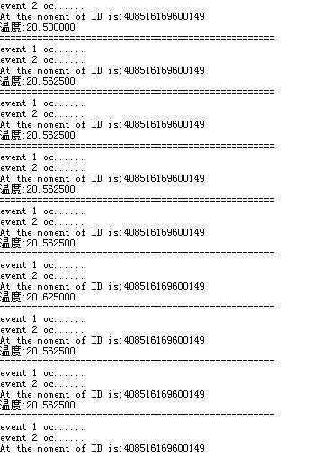
printf("At the moment of ID is:") ;
for(i=0;i<8;i++) //字符不能直接输出,要按位输出
{
printf("%u",ID[i]);//输出地址
}
printf("\r\n") ;
}
if(flag == 500)
{
printf("温度:%f\r\n",Read_T());//读取温度并输出
printf("===================================================\r\n");
}
}
}
#ifdef USE_FULL_ASSERT
/**
* @brief Reports the name of the source file and the source line number
* where the assert_param error has occurred.
* @param file: pointer to the source file name
* @param line: assert_param error line source number
* @retval None
*/
void assert_failed(uint8_t* file, uint32_t line)
{
/* User can add his own implementation to report the file name and line number,
ex: printf("Wrong parameters value: file %s on line %d\r\n", file, line) */
/* Infinite loop */
while (1)
{
}
}
#endif
/**
* @}
*/
/**
* @}
*/
#ifdef __GNUC__
/* With GCC/RAISONANCE, small printf (option LD Linker->Libraries->Small printf
set to 'Yes') calls __io_putchar() */
#define PUTCHAR_PROTOTYPE int __io_putchar(int ch)
#else
#define PUTCHAR_PROTOTYPE int fputc(int ch, FILE *f)
#endif /* __GNUC__ */
/**
* @brief Retargets the C library printf function to the USART.
* @param None
* @retval None
*/
PUTCHAR_PROTOTYPE
{
/* Place your implementation of fputc here */
/* e.g. write a character to the USART */
USART_SendData(EVAL_COM1, (uint8_t) ch);
/* Loop until the end of transmission */
while (USART_GetFlagStatus(EVAL_COM1, USART_FLAG_TC) == RESET)
{}
return ch;
}
#ifdef USE_FULL_ASSERT
/**
* @brief Reports the name of the source file and the source line number
* where the assert_param error has occurred.
* @param file: pointer to the source file name
* @param line: assert_param error line source number
* @retval None
*/
void assert_failed(uint8_t* file, uint32_t line)
{
/* User can add his own implementation to report the file name and line number,
ex: printf("Wrong parameters value: file %s on line %d\r\n", file, line) */
/* Infinite loop */
while (1)
{
}
}
#endif
spi
/**
******************************************************************************
* @file EXTI/EXTI_Config/main.c
* @author MCD Application Team
* @version V3.5.0
* @date 08-April-2011
* @brief Main program body
******************************************************************************
* @attention
*
* THE PRESENT FIRMWARE WHICH IS FOR GUIDANCE ONLY AIMS AT PROVIDING CUSTOMERS
* WITH CODING INFORMATION REGARDING THEIR PRODUCTS IN ORDER FOR THEM TO SAVE
* TIME. AS A RESULT, STMICROELECTRONICS SHALL NOT BE HELD LIABLE FOR ANY
* DIRECT, INDIRECT OR CONSEQUENTIAL DAMAGES WITH RESPECT TO ANY CLAIMS ARISING
* FROM THE CONTENT OF SUCH FIRMWARE AND/OR THE USE MADE BY CUSTOMERS OF THE
* CODING INFORMATION CONTAINED HEREIN IN CONNECTION WITH THEIR PRODUCTS.
*
*
© COPYRIGHT 2011 STMicroelectronics
******************************************************************************
*/
/* Includes ------------------------------------------------------------------*/
#include "stm32f10x.h"
#include "stm32_eval.h"
#include
#include "spi_flash.h"
#define VREF 3.3
void delay_us(u32 n)
{
u8 j;
while(n--)
for(j=0;j<10;j++);
}
void delay_ms(u32 n)
{
while(n--)
delay_us(1000);
}
#define TxBufferSize1 (countof(TxBuffer1) - 1)
#define RxBufferSize1 (countof(TxBuffer1) - 1)
#define countof(a) (sizeof(a) / sizeof(*(a)))
#define BufferSize (countof(Tx_Buffer)-1)
typedef enum { FAILED = 0, PASSED = !FAILED} TestStatus;
#define FLASH_WriteAddress 0x00000
#define FLASH_ReadAddress FLASH_WriteAddress
#define FLASH_SectorToErase FLASH_WriteAddress
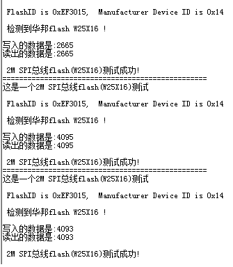
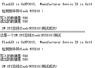
#define sFLASH_ID 0xEF3015 //W25X16
//#define sFLASH_ID 0xEF4015 //W25Q16
#define buff_size 16;
char rx_buff[],rx_buff_count=0;
/* ???????? */
uint8_t Tx_Buffer[4096] ;
uint8_t Rx_Buffer[BufferSize];
__IO uint32_t DeviceID = 0;
__IO uint32_t FlashID = 0;
__IO TestStatus TransferStatus1 = FAILED;
// ??????
void Delay(__IO uint32_t nCount);
TestStatus Buffercmp(uint8_t* pBuffer1, uint8_t* pBuffer2, uint16_t BufferLength);
/** @addtogroup STM32F10x_StdPeriph_Examples
* @{
*/
/** @addtogroup EXTI_Config
* @{
*/
/* Private typedef -----------------------------------------------------------*/
/* Private define ------------------------------------------------------------*/
/* Private macro -------------------------------------------------------------*/
/* Private variables ---------------------------------------------------------*/
GPIO_InitTypeDef GPIO_InitStructure;
USART_InitTypeDef USART_InitStructure;
USART_ClockInitTypeDef USART_ClockInitStructure;
char *int_to_string(int number,char *strnum)//整形数据转换为字符型
{
int j=0,i=0,n=0;
char temp;
while(number>0)
{
*(strnum+j)=number%10+48;
j++;
number=number/10;
n++;
}
for(i=0;iLibraries->Small printf
set to 'Yes') calls __io_putchar() */
#define PUTCHAR_PROTOTYPE int __io_putchar(int ch)
#else
#define PUTCHAR_PROTOTYPE int fputc(int ch, FILE *f)
#endif /* __GNUC__ */
/**
* @brief Retargets the C library printf function to the USART.
* @param None
* @retval None
*/
PUTCHAR_PROTOTYPE
{
/* Place your implementation of fputc here */
/* e.g. write a character to the USART */
USART_SendData(EVAL_COM1, (uint8_t) ch);
/* Loop until the end of transmission */
while (USART_GetFlagStatus(EVAL_COM1, USART_FLAG_TC) == RESET)
{}
return ch;
}
#ifdef USE_FULL_ASSERT
/**
* @brief Reports the name of the source file and the source line number
* where the assert_param error has occurred.
* @param file: pointer to the source file name
* @param line: assert_param error line source number
* @retval None
*/
void assert_failed(uint8_t* file, uint32_t line)
{
/* User can add his own implementation to report the file name and line number,
ex: printf("Wrong parameters value: file %s on line %d\r\n", file, line) */
/* Infinite loop */
while (1)
{
}
}
#endif
| 有奖活动 | |
|---|---|
| 硬核工程师专属补给计划——填盲盒 | |
| “我踩过的那些坑”主题活动——第002期 | |
| 【EEPW电子工程师创研计划】技术变现通道已开启~ | |
| 发原创文章 【每月瓜分千元赏金 凭实力攒钱买好礼~】 | |
| 【EEPW在线】E起听工程师的声音! | |
| 高校联络员开始招募啦!有惊喜!! | |
| 【工程师专属福利】每天30秒,积分轻松拿!EEPW宠粉打卡计划启动! | |
| 送您一块开发板,2025年“我要开发板活动”又开始了! | |
 我要赚赏金
我要赚赏金 STM32
STM32 MCU
MCU 通讯及无线技术
 物联网技术
物联网技术 电子DIY
电子DIY 板卡试用
板卡试用 基础知识
基础知识 软件与操作系统
 我爱生活
我爱生活 小e食堂
小e食堂

