
在本文中,您将学习如何通过加速度计和MPU6050陀螺仪(也称为“陀螺仪传感器”)生成音乐,使用Wekinator开源软件平台实现机器学习技术。
有关Wekinator平台的有用介绍,请查看我们的制造商机器学习:如何开始使用Wekinator 文章。
该项目的第一步是将MPU6050传感器与Arduino连接,Arduino将输出数据发送到处理中。
在处理过程中,我们将计算YPR(偏航,俯仰,滚转)值并绘制模拟传感器运动的3D模型,然后将值发送到Wekinator。最后,IC输出数据被发送到在处理中产生音乐的鼓机。
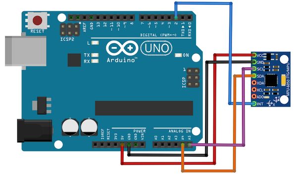
将MPU6050陀螺仪连接到Arduino的方向。
输入在输入侧,传感器需要连接到Arduino。这样做的说明如下图所示。
安装Arduino库要将Arduino与传感器正确连接,首先要下载为此目的开发的Arduino库。您还需要I2C库,您可以通过此文件夹访问该库。
接下来,解压缩文件内容,打开标题为“Arduino”的文件夹,并将I2C和MPU6050传感器文件夹移动到Arduino库文件夹。
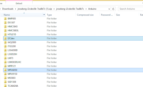
示例指示I2C dev和MPU6050文件夹的选定位置。
上传代码首先启动Arduino IDE软件。导航到“文件”下的示例,然后导航到MPU6050并打开MPU6050_DMP6文件。
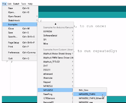
演示如何在Arduino IDE中导航到MPU6050_DMP6文件的示例。
上传Arduino IDE中的代码,它应显示在串行监视器上。
如果它显示输出数据,那么您可以假设传感器已成功与Arduino连接。
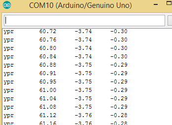
确认MPU605传感器的窗口中显示的输出数据已成功连接到Arduino。
要将数据发送到处理,需要对代码进行一些更改。
首先,选择代码的第117行并取消注释,向上移动到第100行并注释该段代码。如果您在执行此步骤时遇到问题,请参考下图。
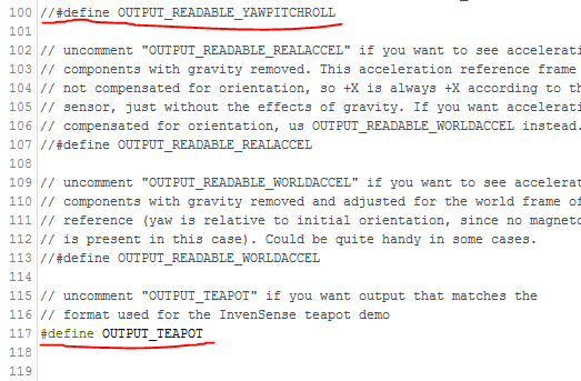
一个示例,用于强调需要更改的代码行。
如果再次上载代码,它将在串行监视器上显示不可读的字符。
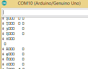
串行监视器窗口中不可读字符代码的示例。
处理代码为了从Arduino接收数据,您将使用'toxiclibs'库。
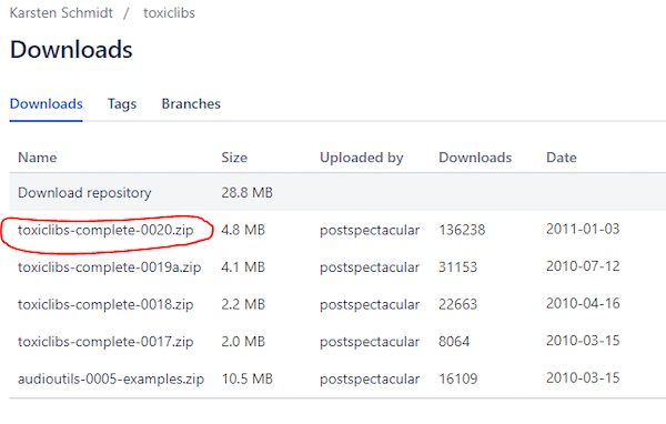
参考图像,指示'toxiclibs'库文件的圆圈位置。
接下来,将整个文件夹复制到zip文件中并将其粘贴到处理库文件夹中。您将导航到'yourProcessingFolder',模式,java,然后导航到库类别。
现在将下面提供的代码(传感器库中的示例的修改版本)粘贴到处理中并上传。
import processing.serial.*;
import processing.opengl.*;
import toxi.geom.*;
import toxi.processing.*;
import oscP5.*;
import netP5.*;
OscP5 oscP5;
NetAddress dest;
ToxiclibsSupport gfx;
Serial port; // The serial port
char[] teapotPacket = new char[14]; // InvenSense Teapot packet
int serialCount = 0; // current packet byte position
int synced = 0;
int interval = 0;
float[] q = new float[4];
Quaternion quat = new Quaternion(1, 0, 0, 0);
float[] gravity = new float[3];
float[] euler = new float[3];
float[] ypr = new float[3];
void setup() {
// 300px square viewport using OpenGL rendering
size(300, 300, OPENGL);
gfx = new ToxiclibsSupport(this);
// setup lights and antialiasing
lights();
smooth();
// display serial port list for debugging/clarity
println(Serial.list());
// get the first available port (use EITHER this OR the specific port code below)
String portName = Serial.list()[0];
// get a specific serial port (use EITHER this OR the first-available code above)
//String portName = "COM4";
// open the serial port
port = new Serial(this, portName, 115200);
// send single character to trigger DMP init/start
// (expected by MPU6050_DMP6 example Arduino sketch)
port.write('r');
/* start oscP5, sending messages at port 9000 */
oscP5 = new OscP5(this,9000);
dest = new NetAddress("127.0.0.1",6448);
}
void draw() {
if (millis() - interval > 1000) {
// resend single character to trigger DMP init/start
// in case the MPU is halted/reset while applet is running
port.write('r');
interval = millis();
}
// black background
background(0);
// translate everything to the middle of the viewport
pushMatrix();
translate(width / 2, height / 2);
// 3-step rotation from yaw/pitch/roll angles (gimbal lock!)
// ...and other weirdness I haven't figured out yet
//rotateY(-ypr[0]);
//rotateZ(-ypr[1]);
//rotateX(-ypr[2]);
// toxiclibs direct angle/axis rotation from quaternion (NO gimbal lock!)
// (axis order [1, 3, 2] and inversion [-1, +1, +1] is a consequence of
// different coordinate system orientation assumptions between Processing
// and InvenSense DMP)
float[] axis = quat.toAxisAngle();
rotate(axis[0], -axis[1], axis[3], axis[2]);
// draw main body in red
fill(255, 0, 0, 200);
box(10, 10, 200);
// draw front-facing tip in blue
fill(0, 0, 255, 200);
pushMatrix();
translate(0, 0, -120);
rotateX(PI/2);
drawCylinder(0, 20, 20, 8);
popMatrix();
// draw wings and tail fin in green
fill(0, 255, 0, 200);
beginShape(TRIANGLES);
vertex(-100, 2, 30); vertex(0, 2, -80); vertex(100, 2, 30); // wing top layer
vertex(-100, -2, 30); vertex(0, -2, -80); vertex(100, -2, 30); // wing bottom layer
vertex(-2, 0, 98); vertex(-2, -30, 98); vertex(-2, 0, 70); // tail left layer
vertex( 2, 0, 98); vertex( 2, -30, 98); vertex( 2, 0, 70); // tail right layer
endShape();
beginShape(QUADS);
vertex(-100, 2, 30); vertex(-100, -2, 30); vertex( 0, -2, -80); vertex( 0, 2, -80);
vertex( 100, 2, 30); vertex( 100, -2, 30); vertex( 0, -2, -80); vertex( 0, 2, -80);
vertex(-100, 2, 30); vertex(-100, -2, 30); vertex(100, -2, 30); vertex(100, 2, 30);
vertex(-2, 0, 98); vertex(2, 0, 98); vertex(2, -30, 98); vertex(-2, -30, 98);
vertex(-2, 0, 98); vertex(2, 0, 98); vertex(2, 0, 70); vertex(-2, 0, 70);
vertex(-2, -30, 98); vertex(2, -30, 98); vertex(2, 0, 70); vertex(-2, 0, 70);
endShape();
popMatrix();
//Send the OSC message
sendOsc();
}
void serialEvent(Serial port) {
interval = millis();
while (port.available() > 0) {
int ch = port.read();
if (synced == 0 && ch != '$') return; // initial synchronization - also used to resync/realign if needed
synced = 1;
print ((char)ch);
if ((serialCount == 1 && ch != 2)
|| (serialCount == 12 && ch != '\r')
|| (serialCount == 13 && ch != '\n')) {
serialCount = 0;
synced = 0;
return;
}
if (serialCount > 0 || ch == '$') {
teapotPacket[serialCount++] = (char)ch;
if (serialCount == 14) {
serialCount = 0; // restart packet byte position
// get quaternion from data packet
q[0] = ((teapotPacket[2] << 8) | teapotPacket[3]) / 16384.0f;
q[1] = ((teapotPacket[4] << 8) | teapotPacket[5]) / 16384.0f;
q[2] = ((teapotPacket[6] << 8) | teapotPacket[7]) / 16384.0f;
q[3] = ((teapotPacket[8] << 8) | teapotPacket[9]) / 16384.0f;
for (int i = 0; i < 4; i++) if (q[i] >= 2) q[i] = -4 + q[i];
// set our toxilibs quaternion to new data
quat.set(q[0], q[1], q[2], q[3]);
// below calculations unnecessary for orientation only using toxilibs
// calculate gravity vector
gravity[0] = 2 * (q[1]*q[3] - q[0]*q[2]);
gravity[1] = 2 * (q[0]*q[1] + q[2]*q[3]);
gravity[2] = q[0]*q[0] - q[1]*q[1] - q[2]*q[2] + q[3]*q[3];
// calculate Euler angles
euler[0] = atan2(2*q[1]*q[2] - 2*q[0]*q[3], 2*q[0]*q[0] + 2*q[1]*q[1] - 1);
euler[1] = -asin(2*q[1]*q[3] + 2*q[0]*q[2]);
euler[2] = atan2(2*q[2]*q[3] - 2*q[0]*q[1], 2*q[0]*q[0] + 2*q[3]*q[3] - 1);
// calculate yaw/pitch/roll angles
ypr[0] = atan2(2*q[1]*q[2] - 2*q[0]*q[3], 2*q[0]*q[0] + 2*q[1]*q[1] - 1);
ypr[1] = atan(gravity[0] / sqrt(gravity[1]*gravity[1] + gravity[2]*gravity[2]));
ypr[2] = atan(gravity[1] / sqrt(gravity[0]*gravity[0] + gravity[2]*gravity[2]));
// output various components for debugging
//println("q:\t" + round(q[0]*100.0f)/100.0f + "\t" + round(q[1]*100.0f)/100.0f + "\t" + round(q[2]*100.0f)/100.0f + "\t" + round(q[3]*100.0f)/100.0f);
//println("euler:\t" + euler[0]*180.0f/PI + "\t" + euler[1]*180.0f/PI + "\t" + euler[2]*180.0f/PI);
println("ypr:\t" + ypr[0]*180.0f/PI + "\t" + ypr[1]*180.0f/PI + "\t" + ypr[2]*180.0f/PI);
}
}
}
}
void drawCylinder(float topRadius, float bottomRadius, float tall, int sides) {
float angle = 0;
float angleIncrement = TWO_PI / sides;
beginShape(QUAD_STRIP);
for (int i = 0; i < sides + 1; ++i) {
vertex(topRadius*cos(angle), 0, topRadius*sin(angle));
vertex(bottomRadius*cos(angle), tall, bottomRadius*sin(angle));
angle += angleIncrement;
}
endShape();
// If it is not a cone, draw the circular top cap
if (topRadius != 0) {
angle = 0;
beginShape(TRIANGLE_FAN);
// Center point
vertex(0, 0, 0);
for (int i = 0; i < sides + 1; i++) {
vertex(topRadius * cos(angle), 0, topRadius * sin(angle));
angle += angleIncrement;
}
endShape();
}
// If it is not a cone, draw the circular bottom cap
if (bottomRadius != 0) {
angle = 0;
beginShape(TRIANGLE_FAN);
// Center point
vertex(0, tall, 0);
for (int i = 0; i < sides + 1; i++) {
vertex(bottomRadius * cos(angle), tall, bottomRadius * sin(angle));
angle += angleIncrement;
}
endShape();
}
}
void sendOsc() {
OscMessage msg = new OscMessage("/wek/inputs");
msg.add((float)ypr[2]); // x-axis
msg.add((float)ypr[1]); // y -axis
oscP5.send(msg, dest);
}
上传代码后,应显示如下所示的窗口。
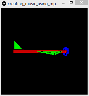
将代码上传到处理后应显示的窗口。
输出就这个项目的输出而言,我们将使用一个处理草图,它接收Wekinator的输出并根据其指令产生音乐。
特定草图将从Wekinator获得三个连续的输出,可 在Wekinator网站的示例页面上找到。
从网页下载“简单连续控制鼓机”文件,并在处理窗口中运行草图。
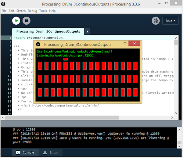
在处理中运行处理草图的示例。
使用Wekinator在Wekinator软件中,您需要设置设置以反映下面示例中显示的设置。
将输入值分配为2并将输出分配给3.另外,将输出类型指定为默认设置“全部连续”。
这将提示Wekinator发送处理所需的3种IC不同输出,并根据值发出不同的音乐。
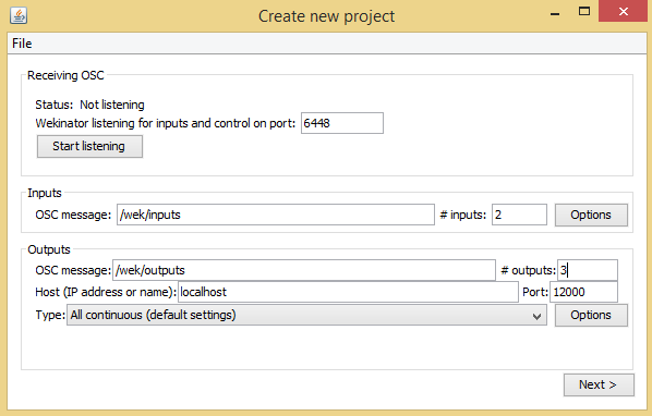
如果单击下一个按钮,您将进入下面显示的“新建项目”窗口。
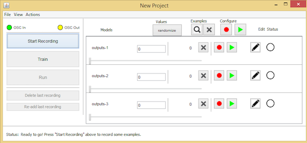
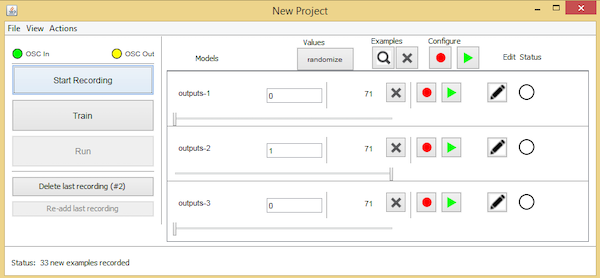
将output1值设置为“1”并尝试向任意方向倾斜传感器。然后,将其他两个输出框设置为“o”并开始录制以创建一些音频样本。
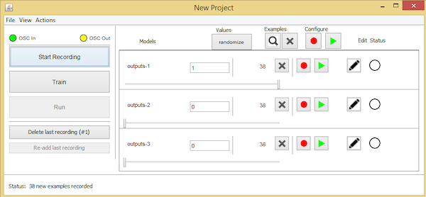
在开始再次记录样品之前,将传感器向另一个方向倾斜并将output2设置为“1”,将另外两个输出区域设置为“0”。
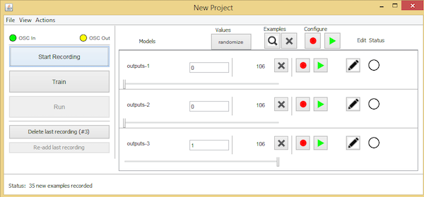
最后,将传感器向您选择的另一个方向倾斜,并将output3设置为“1”,将另外两个设置为“0”。
记录最终样本以检查这些特定值设置的结果。
在将传感器向不同方向倾斜的同时,可以通过记录其他样品来进一步进行实验。
记录样本后,编程Wekinator并运行它。它应该根据传感器的运动产生音乐。
 我要赚赏金
我要赚赏金 STM32
STM32 MCU
MCU 通讯及无线技术
 物联网技术
物联网技术 电子DIY
电子DIY 板卡试用
板卡试用 基础知识
基础知识 软件与操作系统
 我爱生活
我爱生活 小e食堂
小e食堂

