

RGB&七彩灯代码作业
#include "stm32f10x.h"
#include "stm32_eval.h"
#include <stdio.h>
#define VREF 3.3
GPIO_InitTypeDef   GPIO_InitStructure;
USART_InitTypeDef USART_InitStructure;
USART_ClockInitTypeDef USART_ClockInitStructure;

void RCC_Configuration(void)
{
    SystemInit();
    RCC_APB2PeriphClockCmd(RCC_APB2Periph_GPIOD|RCC_APB2Periph_AFIO, ENABLE);
 GPIO_PinRemapConfig(GPIO_Remap_SWJ_JTAGDisable,ENABLE);//disable JTAG
RCC_APB2PeriphClockCmd(RCC_APB2Periph_GPIOD|RCC_APB2Periph_AFIO, ENABLE);
 GPIO_PinRemapConfig(GPIO_Remap_SWJ_JTAGDisable,ENABLE);//disable JTAG
  GPIO_InitStructure.GPIO_Pin = GPIO_Pin_2;
  GPIO_InitStructure.GPIO_Speed = GPIO_Speed_50MHz;
  GPIO_InitStructure.GPIO_Mode = GPIO_Mode_Out_PP;
  GPIO_Init(GPIOD, &GPIO_InitStructure);
    GPIO_ResetBits(GPIOD,GPIO_Pin_2);
    RCC_APB2PeriphClockCmd(RCC_APB2Periph_GPIOC|RCC_APB2Periph_AFIO, ENABLE);
 GPIO_PinRemapConfig(GPIO_Remap_SWJ_JTAGDisable,ENABLE);//disable JTAG
  GPIO_InitStructure.GPIO_Pin = GPIO_Pin_0|GPIO_Pin_1|GPIO_Pin_2|GPIO_Pin_3|GPIO_Pin_4|GPIO_Pin_5|GPIO_Pin_6|GPIO_Pin_7;
  GPIO_InitStructure.GPIO_Speed = GPIO_Speed_50MHz;
  GPIO_InitStructure.GPIO_Mode = GPIO_Mode_Out_PP;
  GPIO_Init(GPIOC, &GPIO_InitStructure);
    GPIO_SetBits(GPIOC,GPIO_Pin_0|GPIO_Pin_1|GPIO_Pin_2|GPIO_Pin_3|GPIO_Pin_4|GPIO_Pin_5|GPIO_Pin_6|GPIO_Pin_7);
      RCC_APB1PeriphClockCmd(RCC_APB1Periph_TIM2, ENABLE);
}

void USART_int(long BaudRate)
{
    RCC_APB2PeriphClockCmd(RCC_APB2Periph_GPIOA|RCC_APB2Periph_USART1,ENABLE);
       GPIO_InitStructure.GPIO_Pin = GPIO_Pin_9;
    GPIO_InitStructure.GPIO_Speed = GPIO_Speed_50MHz;
    GPIO_InitStructure.GPIO_Mode = GPIO_Mode_AF_PP;
    GPIO_Init(GPIOA, &GPIO_InitStructure);
    /* PA10 USART1_Rx  */
    GPIO_InitStructure.GPIO_Pin = GPIO_Pin_10;
    GPIO_InitStructure.GPIO_Mode = GPIO_Mode_IN_FLOATING;
    GPIO_Init(GPIOA, &GPIO_InitStructure);
  /* USARTx configured as follow:
        - BaudRate = 115200 baud
        - Word Length = 8 Bits
        - One Stop Bit
        - No parity
        - Hardware flow control disabled (RTS and CTS signals)
        - Receive and transmit enabled
  */
  USART_InitStructure.USART_BaudRate = BaudRate;
  USART_InitStructure.USART_WordLength = USART_WordLength_8b;
  USART_InitStructure.USART_StopBits = USART_StopBits_1;
  USART_InitStructure.USART_Parity = USART_Parity_No;
  USART_InitStructure.USART_HardwareFlowControl = USART_HardwareFlowControl_None;
  USART_InitStructure.USART_Mode = USART_Mode_Rx | USART_Mode_Tx;
    USART_ClockInitStructure.USART_Clock = USART_Clock_Disable;
    USART_ClockInitStructure.USART_CPOL = USART_CPOL_Low;
    USART_ClockInitStructure.USART_CPHA = USART_CPHA_2Edge;
    USART_ClockInitStructure.USART_LastBit = USART_LastBit_Disable;
    USART_ClockInit(USART1, &USART_ClockInitStructure);
  USART_Init(USART1, &USART_InitStructure);
  USART_Cmd(USART1, ENABLE);
    USART_ITConfig(USART1, USART_IT_RXNE, ENABLE);
 USART_Cmd(USART1, ENABLE);
}

void PWM_Config()
{uint16_t PrescalerValue = 0;//预分频器值
    TIM_TimeBaseInitTypeDef  TIM_TimeBaseStructure;
TIM_OCInitTypeDef  TIM_OCInitStructure;
    /* TIM2 clock enable */
  RCC_APB1PeriphClockCmd(RCC_APB1Periph_TIM2, ENABLE);
  /* GPIOA  enable */
  RCC_APB2PeriphClockCmd(RCC_APB2Periph_AFIO  , ENABLE);//使能复用功能时钟

        GPIO_InitStructure.GPIO_Pin = GPIO_Pin_1|GPIO_Pin_2|GPIO_Pin_3;
  GPIO_InitStructure.GPIO_Mode = GPIO_Mode_AF_PP;//复用推挽输出
  GPIO_InitStructure.GPIO_Speed = GPIO_Speed_50MHz;
  GPIO_Init(GPIOA, &GPIO_InitStructure);

        TIM_Cmd(TIM2, ENABLE);//TIM2使能
      /* Compute the prescaler value */
  PrescalerValue = (uint16_t) (SystemCoreClock / 24000000) - 1;
  /* Time base configuration */
  TIM_TimeBaseStructure.TIM_Period = 0x07FF;//设置自动重装载
  TIM_TimeBaseStructure.TIM_Prescaler = PrescalerValue;//设置预分频值
  TIM_TimeBaseStructure.TIM_ClockDivision = 0;//设置时钟分割TDTS=Tck_tim
  TIM_TimeBaseStructure.TIM_CounterMode = TIM_CounterMode_Up;//向上计数
  TIM_TimeBaseInit(TIM2, &TIM_TimeBaseStructure);//根据指定参数初始化TIMx
  TIM_OCInitStructure.TIM_OCMode = TIM_OCMode_PWM1;//选择PWM模式1
  TIM_OCInitStructure.TIM_OCPolarity = TIM_OCPolarity_High;//输出极性高
  /* PWM1 Mode configuration: Channel2 */
  TIM_OCInitStructure.TIM_OutputState = TIM_OutputState_Enable;
  TIM_OCInitStructure.TIM_Pulse = 0xFFFF;//通道占空比时间
  TIM_OC2Init(TIM2, &TIM_OCInitStructure);//初始化TIM2 OC2
    /* PWM1 Mode configuration: Channel3 */
  TIM_OCInitStructure.TIM_OutputState = TIM_OutputState_Enable;//比较输出使能
  TIM_OCInitStructure.TIM_Pulse = 0xFFFF;//通道占空比时间
  TIM_OC3Init(TIM2, &TIM_OCInitStructure);//初始化TIM2 OC3
    /* PWM1 Mode configuration: Channel4 */
  TIM_OCInitStructure.TIM_OutputState = TIM_OutputState_Enable;
  TIM_OCInitStructure.TIM_Pulse = 0xFFFF;//通道占空比时间
  TIM_OC4Init(TIM2, &TIM_OCInitStructure);//初始化TIM2 OC4

  TIM_ARRPreloadConfig(TIM2, ENABLE);//使能预装载寄存器
}

void delay_us(u32 n)
{
    u8 j;
    while(n--)
    for(j=0;j<10;j++);
}
void  delay_ms(u32 n)
{
    while(n--)
    delay_us(1000);
}
void PWM_TEST()
{ unsigned int temp0,temp1,temp2;
    printf("PWM-RGB TEST......\r\n");
    while(1)
    {
      if(temp0=2000,temp1=2000,temp2=0)
             {TIM_SetCompare2(TIM2,temp0);delay_ms(500);
       TIM_SetCompare3(TIM2,temp1);delay_ms(500);
       TIM_SetCompare4(TIM2,temp2);delay_ms(500);
            }
     if(temp0=1900,temp1=0,temp2=1900)
          {TIM_SetCompare2(TIM2,temp0);delay_ms(500);
       TIM_SetCompare3(TIM2,temp1);delay_ms(500);
       TIM_SetCompare4(TIM2,temp2);delay_ms(500);
          }
			 if(temp0=0,temp1=2000,temp2=2000)
           {TIM_SetCompare2(TIM2,temp0);delay_ms(400);
       TIM_SetCompare3(TIM2,temp1);delay_ms(500);
       TIM_SetCompare4(TIM2,temp2);delay_ms(500);
      }

    if(temp0=250,temp1=1700,temp2=1700)
             {TIM_SetCompare2(TIM2,temp0);delay_ms(500);
       TIM_SetCompare3(TIM2,temp1);delay_ms(500);
       TIM_SetCompare4(TIM2,temp2);delay_ms(500);
            }
    if(temp0=500,temp1=300,temp2=1800)
             {TIM_SetCompare2(TIM2,temp0);delay_ms(500);
       TIM_SetCompare3(TIM2,temp1);delay_ms(500);
       TIM_SetCompare4(TIM2,temp2);delay_ms(500);
            }
    if(temp0=400,temp1=1500,temp2=1000)
             {TIM_SetCompare2(TIM2,temp0);delay_ms(500);
       TIM_SetCompare3(TIM2,temp1);delay_ms(500);
       TIM_SetCompare4(TIM2,temp2);delay_ms(500);
            }
   if(temp0=1300,temp1=800,temp2=1200)
             {TIM_SetCompare2(TIM2,temp0);delay_ms(500);
       TIM_SetCompare3(TIM2,temp1);delay_ms(500);
       TIM_SetCompare4(TIM2,temp2);delay_ms(500);
            }
         }
}
int main(void)
{
  RCC_Configuration();
USART_int(115200);
    printf(" config done...\r\n");
    PWM_Config();
    delay_ms(1000);
    while(1)
    {
        PWM_TEST();
    }
}
#ifdef  USE_FULL_ASSERT
void assert_failed(uint8_t* file, uint32_t line)
{while (1)
  {
  }
}
#endif

#ifdef __GNUC__
  #define PUTCHAR_PROTOTYPE int __io_putchar(int ch)
#else
  #define PUTCHAR_PROTOTYPE int fputc(int ch, FILE *f)
#endif /* __GNUC__ */
PUTCHAR_PROTOTYPE
{
  USART_SendData(EVAL_COM1, (uint8_t) ch);
  /* Loop until the end of transmission */
  while (USART_GetFlagStatus(EVAL_COM1, USART_FLAG_TC) == RESET)
  {}
  return ch;
}
#ifdef  USE_FULL_ASSERT
etval None
  */
void assert_failed(uint8_t* file, uint32_t line)
{
  while (1)
  {
  }
}
#endif

ADC 控制RGB颜色作业代码与视频
这是在之前PWM的基础上简单更改的,加上了ADC的结构体 初始化 还有一些参数.
/* Includes ------------------------------------------------------------------*/
#include "stm32f10x.h"
#include "stm32_eval.h"
#include
#define VREF 3.3

/* Private typedef -----------------------------------------------------------*/
/* Private define ------------------------------------------------------------*/
/* Private macro -------------------------------------------------------------*/
/* Private variables ---------------------------------------------------------*/
GPIO_InitTypeDef   GPIO_InitStructure;
USART_InitTypeDef USART_InitStructure;
USART_ClockInitTypeDef USART_ClockInitStructure;

void RCC_Configuration(void)
{
    SystemInit();
    RCC_APB2PeriphClockCmd(RCC_APB2Periph_GPIOD|RCC_APB2Periph_AFIO, ENABLE);
 GPIO_PinRemapConfig(GPIO_Remap_SWJ_JTAGDisable,ENABLE);//disable JTAG
RCC_APB2PeriphClockCmd(RCC_APB2Periph_GPIOD|RCC_APB2Periph_AFIO, ENABLE);
 GPIO_PinRemapConfig(GPIO_Remap_SWJ_JTAGDisable,ENABLE);//disable JTAG
  GPIO_InitStructure.GPIO_Pin = GPIO_Pin_2;
  GPIO_InitStructure.GPIO_Speed = GPIO_Speed_50MHz;
  GPIO_InitStructure.GPIO_Mode = GPIO_Mode_Out_PP;
  GPIO_Init(GPIOD, &GPIO_InitStructure);
    GPIO_ResetBits(GPIOD,GPIO_Pin_2);
    RCC_APB2PeriphClockCmd(RCC_APB2Periph_GPIOC|RCC_APB2Periph_AFIO, ENABLE);
 GPIO_PinRemapConfig(GPIO_Remap_SWJ_JTAGDisable,ENABLE);//disable JTAG
 RCC_APB1PeriphClockCmd(RCC_APB1Periph_TIM2, ENABLE);
}

void USART_int(long BaudRate)
{
    RCC_APB2PeriphClockCmd(RCC_APB2Periph_GPIOA|RCC_APB2Periph_USART1,ENABLE);
       GPIO_InitStructure.GPIO_Pin = GPIO_Pin_9;
    GPIO_InitStructure.GPIO_Speed = GPIO_Speed_10MHz;
    GPIO_InitStructure.GPIO_Mode = GPIO_Mode_AF_PP;
    GPIO_Init(GPIOA, &GPIO_InitStructure);
    /* PA10 USART1_Rx  */
    GPIO_InitStructure.GPIO_Pin = GPIO_Pin_10;
    GPIO_InitStructure.GPIO_Mode = GPIO_Mode_IN_FLOATING;
    GPIO_Init(GPIOA, &GPIO_InitStructure);
  /* USARTx configured as follow:
        - BaudRate = 115200 baud
        - Word Length = 8 Bits
        - One Stop Bit
        - No parity
        - Hardware flow control disabled (RTS and CTS signals)
        - Receive and transmit enabled
  */
  USART_InitStructure.USART_BaudRate = BaudRate;//??????
  USART_InitStructure.USART_WordLength = USART_WordLength_8b;//???????8bit
  USART_InitStructure.USART_StopBits = USART_StopBits_1;//????1
  USART_InitStructure.USART_Parity = USART_Parity_No;//????
  USART_InitStructure.USART_HardwareFlowControl = USART_HardwareFlowControl_None;//??????none
  USART_InitStructure.USART_Mode = USART_Mode_Rx | USART_Mode_Tx;//??????????
    USART_ClockInitStructure.USART_Clock = USART_Clock_Disable;
    USART_ClockInitStructure.USART_CPOL = USART_CPOL_Low;
    USART_ClockInitStructure.USART_CPHA = USART_CPHA_2Edge;
    USART_ClockInitStructure.USART_LastBit = USART_LastBit_Disable;
    USART_ClockInit(USART1, &USART_ClockInitStructure);
  USART_Init(USART1, &USART_InitStructure);
  USART_Cmd(USART1, ENABLE);
    USART_ITConfig(USART1, USART_IT_RXNE, ENABLE);
 USART_Cmd(USART1, ENABLE);
}

void delay_us(u32 n)
{
    u8 j;
    while(n--)
    for(j=0;j<10;j++);
}
void  delay_ms(u32 n)
{
    while(n--)
    delay_us(1000);
}

void PWM_Config()
{uint16_t PrescalerValue = 0;
    TIM_TimeBaseInitTypeDef  TIM_TimeBaseStructure;
TIM_OCInitTypeDef  TIM_OCInitStructure;
    /* TIM2 clock enable */
  RCC_APB1PeriphClockCmd(RCC_APB1Periph_TIM2, ENABLE);
  /* GPIOA  enable */
  RCC_APB2PeriphClockCmd(RCC_APB2Periph_AFIO  , ENABLE);

        GPIO_InitStructure.GPIO_Pin = GPIO_Pin_1|GPIO_Pin_2|GPIO_Pin_3;
  GPIO_InitStructure.GPIO_Mode = GPIO_Mode_AF_PP;
  GPIO_InitStructure.GPIO_Speed = GPIO_Speed_50MHz;
  GPIO_Init(GPIOA, &GPIO_InitStructure);
        TIM_Cmd(TIM2, ENABLE);
      /* Compute the prescaler value */
  PrescalerValue = (uint16_t) (SystemCoreClock / 24000000) - 1;
  /* Time base configuration */
  TIM_TimeBaseStructure.TIM_Period = 0x07FF;
  TIM_TimeBaseStructure.TIM_Prescaler = PrescalerValue;
  TIM_TimeBaseStructure.TIM_ClockDivision = 0;
  TIM_TimeBaseStructure.TIM_CounterMode = TIM_CounterMode_Up;
  TIM_TimeBaseInit(TIM2, &TIM_TimeBaseStructure);
  TIM_OCInitStructure.TIM_OCMode = TIM_OCMode_PWM1;
  TIM_OCInitStructure.TIM_OCPolarity = TIM_OCPolarity_High;
  /* PWM1 Mode configuration: Channel2 */
  TIM_OCInitStructure.TIM_OutputState = TIM_OutputState_Enable;
  TIM_OCInitStructure.TIM_Pulse = 0xFFFF;
  TIM_OC2Init(TIM2, &TIM_OCInitStructure);
    /* PWM1 Mode configuration: Channel3 */
  TIM_OCInitStructure.TIM_OutputState = TIM_OutputState_Enable;
  TIM_OCInitStructure.TIM_Pulse = 0xFFFF;
  TIM_OC3Init(TIM2, &TIM_OCInitStructure);
    /* PWM1 Mode configuration: Channel4 */
  TIM_OCInitStructure.TIM_OutputState = TIM_OutputState_Enable;
  TIM_OCInitStructure.TIM_Pulse = 0xFFFF;
  TIM_OC4Init(TIM2, &TIM_OCInitStructure);
  TIM_ARRPreloadConfig(TIM2, ENABLE);
}


void ADC_CONFIG(){
    ADC_InitTypeDef ADC_InitStructure;
    #if defined (STM32F10X_LD_VL) || defined (STM32F10X_MD_VL) || defined (STM32F10X_HD_VL)
  /* ADCCLK = PCLK2/2 */
  RCC_ADCCLKConfig(RCC_PCLK2_Div2);   //复位ADC1,同时设置分频因子
#else
  /* ADCCLK = PCLK2/4 */
  RCC_ADCCLKConfig(RCC_PCLK2_Div4);
#endif
ADC_DeInit(ADC1);
  /* Enable ADC1 and GPIOC clock */
  RCC_APB2PeriphClockCmd(RCC_APB2Periph_ADC1 | RCC_APB2Periph_GPIOB, ENABLE);

    /* Configure PB0 (ADC Channel14) as analog input -------------------------*/
  GPIO_InitStructure.GPIO_Pin = GPIO_Pin_0;
  GPIO_InitStructure.GPIO_Mode = GPIO_Mode_AIN;
  GPIO_Init(GPIOB, &GPIO_InitStructure);


  /* ADC1 configuration ------------------------------------------------------*/
  ADC_InitStructure.ADC_Mode = ADC_Mode_Independent;  //ADC工作模式:独立模式
  ADC_InitStructure.ADC_ScanConvMode = ENABLE;  //AD单通道模式
  ADC_InitStructure.ADC_ContinuousConvMode = ENABLE;  //AD单次转换模式
  ADC_InitStructure.ADC_ExternalTrigConv = ADC_ExternalTrigConv_None;  //转换由软件而不是外部触发启动
  ADC_InitStructure.ADC_DataAlign = ADC_DataAlign_Right;  //ADC数据右对齐
  ADC_InitStructure.ADC_NbrOfChannel = 1;  //顺序进行规则转换的ADC通道的数目1
  ADC_Init(ADC1, &ADC_InitStructure);  //根据指定参数初始化外设ADC1
  /* Enable ADC1 DMA */
  ADC_DMACmd(ADC1, ENABLE);
  /* Enable ADC1 */
  ADC_Cmd(ADC1, ENABLE);
}
 int Get_ADC(){
     /* ADC1 regular channel configuration */
  ADC_RegularChannelConfig(ADC1, ADC_Channel_8, 1, ADC_SampleTime_55Cycles5);  //规则序列中的第1个转换,采样周期为55.5
    /* Enable ADC1 reset calibration register */
  ADC_ResetCalibration(ADC1);  //执行复位校准
  /* Check the end of ADC1 reset calibration register */
  while(ADC_GetResetCalibrationStatus(ADC1));
   /* Start ADC1 calibration */
  ADC_StartCalibration(ADC1);  //执行ADC校准,开始指定的ADC1的校准状态
  /* Check the end of ADC1 calibration */
  while(ADC_GetCalibrationStatus(ADC1));
  /* Start ADC1 Software Conversion */
  ADC_SoftwareStartConvCmd(ADC1, ENABLE);  //软件开启ADC转换
    return ADC_GetConversionValue(ADC1);
}
  void PWM_TEST()
{
    float Volt=0.00;
    unsigned int temp0,temp1,temp2,ADValue = 0;
    while(1)
{
      ADValue = Get_ADC();
        Volt = VREF*ADValue/4095;
        printf("PWM-RGB & ADC TEST......\r\n\r\n");
        printf("The ADC value is:%d\r\n",ADValue);
        printf("The Volt is:%f V\r\n",Volt);
      TIM_SetCompare2(TIM2, temp0);
      TIM_SetCompare3(TIM2, temp1);
      TIM_SetCompare4(TIM2, temp2);
        if(ADValue>3000)
         {  temp0=ADValue/2;temp1=ADValue/2;temp2=ADValue/2-1500;
         }
                 if(2000Libraries->Small printf
     set to 'Yes') calls __io_putchar() */
  #define PUTCHAR_PROTOTYPE int __io_putchar(int ch)
#else
  #define PUTCHAR_PROTOTYPE int fputc(int ch, FILE *f)
#endif /* __GNUC__ */
PUTCHAR_PROTOTYPE
{
  /* Place your implementation of fputc here */
  /* e.g. write a character to the USART */
  USART_SendData(EVAL_COM1, (uint8_t) ch);

  /* Loop until the end of transmission */
  while (USART_GetFlagStatus(EVAL_COM1, USART_FLAG_TC) == RESET)
  {}
  return ch;
}
  #ifdef  USE_FULL_ASSERT
void assert_failed(uint8_t* file, uint32_t line)
{
  while (1)
  {
  }
}

#endif
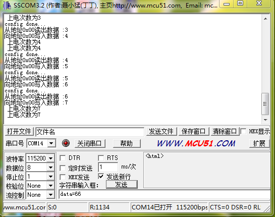
IIC-计上电次数作业代码
#include "stm32f10x.h"
#include "stm32_eval.h"
#include
#define VREF 3.3
unsigned char i=0;
void EXTIkeyS1_Config(void);
/* Private typedef -----------------------------------------------------------*/
/* Private define ------------------------------------------------------------*/
/* Private macro -------------------------------------------------------------*/
/* Private variables ---------------------------------------------------------*/
GPIO_InitTypeDef   GPIO_InitStructure;
USART_InitTypeDef USART_InitStructure;
USART_ClockInitTypeDef USART_ClockInitStructure;
EXTI_InitTypeDef   EXTI_InitStructure;
NVIC_InitTypeDef   NVIC_InitStructure;
void RCC_Configuration(void)
{
  RCC_DeInit();
  RCC_HSICmd(ENABLE);
  while(RCC_GetFlagStatus(RCC_FLAG_HSIRDY) == RESET);
  RCC_SYSCLKConfig(RCC_SYSCLKSource_HSI);
  RCC_HSEConfig(RCC_HSE_OFF);
  RCC_LSEConfig(RCC_LSE_OFF);
  RCC_PLLConfig(RCC_PLLSource_HSI_Div2,RCC_PLLMul_9); //  72HMz
  RCC_PLLCmd(ENABLE);
  while(RCC_GetFlagStatus(RCC_FLAG_PLLRDY) == RESET);
  RCC_ADCCLKConfig(RCC_PCLK2_Div4);
  RCC_PCLK2Config(RCC_HCLK_Div1);
  RCC_PCLK1Config(RCC_HCLK_Div2);
  RCC_HCLKConfig(RCC_SYSCLK_Div1);
  RCC_SYSCLKConfig(RCC_SYSCLKSource_PLLCLK);
  while(RCC_GetSYSCLKSource() != 0x08);
    //SystemInit();
    RCC_APB2PeriphClockCmd(RCC_APB2Periph_GPIOD|RCC_APB2Periph_AFIO, ENABLE);
  GPIO_PinRemapConfig(GPIO_Remap_SWJ_JTAGDisable,ENABLE);//disable JTAG
  RCC_APB2PeriphClockCmd(RCC_APB2Periph_GPIOD|RCC_APB2Periph_AFIO, ENABLE);
  GPIO_PinRemapConfig(GPIO_Remap_SWJ_JTAGDisable,ENABLE);//disable JTAG
  GPIO_InitStructure.GPIO_Pin = GPIO_Pin_2;
  GPIO_InitStructure.GPIO_Speed = GPIO_Speed_50MHz;
  GPIO_InitStructure.GPIO_Mode = GPIO_Mode_Out_PP;
  GPIO_Init(GPIOD, &GPIO_InitStructure);
    GPIO_ResetBits(GPIOD,GPIO_Pin_2);
    RCC_APB2PeriphClockCmd(RCC_APB2Periph_GPIOC|RCC_APB2Periph_AFIO, ENABLE);
  GPIO_PinRemapConfig(GPIO_Remap_SWJ_JTAGDisable,ENABLE);//disable JTAG
  GPIO_InitStructure.GPIO_Pin = GPIO_Pin_0|GPIO_Pin_1|GPIO_Pin_2|GPIO_Pin_3|GPIO_Pin_4|GPIO_Pin_5|GPIO_Pin_6|GPIO_Pin_7;
  GPIO_InitStructure.GPIO_Speed = GPIO_Speed_50MHz;
  GPIO_InitStructure.GPIO_Mode = GPIO_Mode_Out_PP;
  GPIO_Init(GPIOC, &GPIO_InitStructure);
    GPIO_SetBits(GPIOC,GPIO_Pin_0|GPIO_Pin_1|GPIO_Pin_2|GPIO_Pin_3|GPIO_Pin_4|GPIO_Pin_5|GPIO_Pin_6|GPIO_Pin_7);
      RCC_APB1PeriphClockCmd(RCC_APB1Periph_TIM2, ENABLE);
}

void USART_int(long BaudRate)
{
      RCC_APB2PeriphClockCmd(RCC_APB2Periph_GPIOA|RCC_APB2Periph_USART1,ENABLE);
    GPIO_InitStructure.GPIO_Pin = GPIO_Pin_9;
    GPIO_InitStructure.GPIO_Speed = GPIO_Speed_50MHz;
    GPIO_InitStructure.GPIO_Mode = GPIO_Mode_AF_PP;
    GPIO_Init(GPIOA, &GPIO_InitStructure);
    /* PA10 USART1_Rx  */
    GPIO_InitStructure.GPIO_Pin = GPIO_Pin_10;
    GPIO_InitStructure.GPIO_Mode = GPIO_Mode_IN_FLOATING;
    GPIO_Init(GPIOA, &GPIO_InitStructure);
  /* USARTx configured as follow:
        - BaudRate = 115200 baud
        - Word Length = 8 Bits
        - One Stop Bit
        - No parity
        - Hardware flow control disabled (RTS and CTS signals)
        - Receive and transmit enabled
  */
  USART_InitStructure.USART_BaudRate = BaudRate;//??????
  USART_InitStructure.USART_WordLength = USART_WordLength_8b;//???????8bit
  USART_InitStructure.USART_StopBits = USART_StopBits_1;//????1
  USART_InitStructure.USART_Parity = USART_Parity_No;//????
  USART_InitStructure.USART_HardwareFlowControl = USART_HardwareFlowControl_None;//??????none
  USART_InitStructure.USART_Mode = USART_Mode_Rx | USART_Mode_Tx;//??????????
    USART_ClockInitStructure.USART_Clock = USART_Clock_Disable;
    USART_ClockInitStructure.USART_CPOL = USART_CPOL_Low;
    USART_ClockInitStructure.USART_CPHA = USART_CPHA_2Edge;
    USART_ClockInitStructure.USART_LastBit = USART_LastBit_Disable;
    USART_ClockInit(USART1, &USART_ClockInitStructure);
  USART_Init(USART1, &USART_InitStructure);
  USART_Cmd(USART1, ENABLE);
    USART_ITConfig(USART1, USART_IT_RXNE, ENABLE);
  USART_Cmd(USART1, ENABLE);
      /* Configure four bit for preemption priority */
  NVIC_PriorityGroupConfig(NVIC_PriorityGroup_4);
  /* Enable the USART1 Interrupt */
  NVIC_InitStructure.NVIC_IRQChannel = USART1_IRQn; //
  NVIC_InitStructure.NVIC_IRQChannelPreemptionPriority = 15;
  NVIC_InitStructure.NVIC_IRQChannelCmd = ENABLE;
  NVIC_Init(&NVIC_InitStructure);
}

void IIc2_Init(void)
{
        GPIO_InitTypeDef GPIO_InitStructure;
        I2C_InitTypeDef I2C_InitStructure;

        RCC_APB2PeriphClockCmd(RCC_APB2Periph_GPIOB, ENABLE);
        RCC_APB1PeriphClockCmd(RCC_APB1Periph_I2C2, ENABLE);
        //PB6-I2C2_SCL PB7-I2C2_SDA PB10-I2C2_SCL PB11-I2C2_SDA
        /* Configure IO connected to IIC*********************/
        GPIO_InitStructure.GPIO_Pin =  GPIO_Pin_10 | GPIO_Pin_11;
        GPIO_InitStructure.GPIO_Speed = GPIO_Speed_50MHz;
        GPIO_InitStructure.GPIO_Mode = GPIO_Mode_AF_OD;
        GPIO_Init(GPIOB, &GPIO_InitStructure);

        I2C_InitStructure.I2C_Mode = I2C_Mode_I2C;
        I2C_InitStructure.I2C_DutyCycle = I2C_DutyCycle_2;
        I2C_InitStructure.I2C_OwnAddress1 = 0xA0;
        I2C_InitStructure.I2C_Ack = I2C_Ack_Enable;
        I2C_InitStructure.I2C_AcknowledgedAddress = I2C_AcknowledgedAddress_7bit;
        I2C_InitStructure.I2C_ClockSpeed = 400000;
        I2C_Cmd(I2C2, ENABLE);
        I2C_Init(I2C2, &I2C_InitStructure);
        I2C_AcknowledgeConfig(I2C2, ENABLE);
}

void I2C2_WriteByte(unsigned char id,unsigned char write_address,unsigned char byte)
{
        while(I2C_GetFlagStatus(I2C2, I2C_FLAG_BUSY));
        I2C_GenerateSTART(I2C2,ENABLE);
        while(!I2C_CheckEvent(I2C2, I2C_EVENT_MASTER_MODE_SELECT));
        I2C_Send7bitAddress(I2C2,id,I2C_Direction_Transmitter);
        while(!I2C_CheckEvent(I2C2, I2C_EVENT_MASTER_TRANSMITTER_MODE_SELECTED));
        I2C_SendData(I2C2, write_address);
        while(!I2C_CheckEvent(I2C2, I2C_EVENT_MASTER_BYTE_TRANSMITTED));
        I2C_SendData(I2C2, byte);
        while(!I2C_CheckEvent(I2C2, I2C_EVENT_MASTER_BYTE_TRANSMITTED));
        I2C_GenerateSTOP(I2C2, ENABLE);
        do
        {
           /* Send START condition */
           I2C_GenerateSTART(I2C2, ENABLE);
          /* Read I2C2 SR1 register */
            /* Send EEPROM address for write */
            I2C_Send7bitAddress(I2C2, 0xA0, I2C_Direction_Transmitter);
        }while(!(I2C_ReadRegister(I2C2, I2C_Register_SR1) & 0x0002));

        /* Clear AF flag */
        I2C_ClearFlag(I2C2, I2C_FLAG_AF);
        /* STOP condition */
        I2C_GenerateSTOP(I2C2, ENABLE);
}

unsigned char I2C2_ReadByte(unsigned char  id, unsigned char read_address)
{
     unsigned char temp;
     while(I2C_GetFlagStatus(I2C2, I2C_FLAG_BUSY)){}
     I2C_GenerateSTART(I2C2, ENABLE);
     while(!I2C_CheckEvent(I2C2, I2C_EVENT_MASTER_MODE_SELECT));
     I2C_Send7bitAddress(I2C2, id, I2C_Direction_Transmitter);
     while(!I2C_CheckEvent(I2C2, I2C_EVENT_MASTER_TRANSMITTER_MODE_SELECTED));
     I2C_Cmd(I2C2, ENABLE);
     I2C_SendData(I2C2, read_address);
     while(!I2C_CheckEvent(I2C2, I2C_EVENT_MASTER_BYTE_TRANSMITTED));
     I2C_GenerateSTART(I2C2, ENABLE);
     while(!I2C_CheckEvent(I2C2, I2C_EVENT_MASTER_MODE_SELECT));
     I2C_Send7bitAddress(I2C2, id, I2C_Direction_Receiver);
     while(!I2C_CheckEvent(I2C2, I2C_EVENT_MASTER_RECEIVER_MODE_SELECTED));
    I2C_AcknowledgeConfig(I2C2, DISABLE);
    I2C_GenerateSTOP(I2C2, ENABLE);
    while(!(I2C_CheckEvent(I2C2, I2C_EVENT_MASTER_BYTE_RECEIVED)));
    temp = I2C_ReceiveData(I2C2);
    I2C_AcknowledgeConfig(I2C2, ENABLE);
     return temp;
}

/*delay_us*/
void delay_us(u32 n)
{
    u8 j;
    while(n--)
    for(j=0;j<10;j++);
}
/*delay_ms*/

void  delay_ms(u32 n)
{
    while(n--)
    delay_us(1000);
}

int main(void)
{
  RCC_Configuration();
  EXTIkeyS1_Config();
  USART_int(115200);
  IIc2_Init();
    printf(" config done...\r\n");
    i = I2C2_ReadByte(0xA0,0);//向0x00读取数据
    printf("从地址0x00读出数据 :%d\r\n",i);
    i++;
    I2C2_WriteByte(0xA0,0,i);//向0x00写入数据
    printf("向地址0x00写入数据 :%d\r\n",i);
    while(1)
    {
     delay_ms(1000);
     printf(" 上电次数为%d\r\n",i);
    }
}
void EXTIkeyS1_Config(void)//S1 PC8
{
  /* Enable GPIOA clock */
  RCC_APB2PeriphClockCmd(RCC_APB2Periph_GPIOC, ENABLE);
  /* Configure PA.00 pin as input floating */
  GPIO_InitStructure.GPIO_Pin = GPIO_Pin_8;//PC8 S1
  GPIO_InitStructure.GPIO_Mode = GPIO_Mode_IN_FLOATING;
  GPIO_Init(GPIOC, &GPIO_InitStructure);
  /* Enable AFIO clock */
  RCC_APB2PeriphClockCmd(RCC_APB2Periph_AFIO, ENABLE);
  GPIO_EXTILineConfig(GPIO_PortSourceGPIOC, GPIO_PinSource8);
  EXTI_InitStructure.EXTI_Line = EXTI_Line8;
  EXTI_InitStructure.EXTI_Mode = EXTI_Mode_Interrupt;
  EXTI_InitStructure.EXTI_Trigger = EXTI_Trigger_Falling;
  EXTI_InitStructure.EXTI_LineCmd = ENABLE;
  EXTI_Init(&EXTI_InitStructure);
  NVIC_InitStructure.NVIC_IRQChannel = EXTI9_5_IRQn;
  NVIC_InitStructure.NVIC_IRQChannelPreemptionPriority = 0x0F;
  NVIC_InitStructure.NVIC_IRQChannelSubPriority = 0x0F;
  NVIC_InitStructure.NVIC_IRQChannelCmd = ENABLE;
  NVIC_Init(&NVIC_InitStructure);
}
void EXTI9_5_IRQHandler(void)
{
  if(EXTI_GetITStatus(EXTI_Line8) != RESET)
  {
        i=0;
        I2C2_WriteByte(0xA0,0,0);
        printf(" 上电次数为%d\r\n",i);
    /* Clear the  EXTI line 8 pending bit */
    EXTI_ClearITPendingBit(EXTI_Line8);
  }
}
#ifdef  USE_FULL_ASSERT

/**
  * @brief  Reports the name of the source file and the source line number
  *         where the assert_param error has occurred.
  * @param  file: pointer to the source file name
  * @param  line: assert_param error line source number
  * @retval None
  */
void assert_failed(uint8_t* file, uint32_t line)
{
  /* User can add his own implementation to report the file name and line number,
     ex: printf("Wrong parameters value: file %s on line %d\r\n", file, line) */

  /* Infinite loop */
  while (1)
  {
  }
}

#endif

#ifdef __GNUC__
  /* With GCC/RAISONANCE, small printf (option LD Linker->Libraries->Small printf
     set to 'Yes') calls __io_putchar() */
  #define PUTCHAR_PROTOTYPE int __io_putchar(int ch)
#else
  #define PUTCHAR_PROTOTYPE int fputc(int ch, FILE *f)
#endif /* __GNUC__ */

/**
  * @brief  Retargets the C library printf function to the USART.
  * @param  None
  * @retval None
  */
PUTCHAR_PROTOTYPE
{
  /* Place your implementation of fputc here */
  /* e.g. write a character to the USART */
  USART_SendData(EVAL_COM1, (uint8_t) ch);

  /* Loop until the end of transmission */
  while (USART_GetFlagStatus(EVAL_COM1, USART_FLAG_TC) == RESET)
  {}

  return ch;
}

#ifdef  USE_FULL_ASSERT

/**
  * @brief  Reports the name of the source file and the source line number
  *         where the assert_param error has occurred.
  * @param  file: pointer to the source file name
  * @param  line: assert_param error line source number
  * @retval None
  */
void assert_failed(uint8_t* file, uint32_t line)
{
  /* User can add his own implementation to report the file name and line number,
     ex: printf("Wrong parameters value: file %s on line %d\r\n", file, line) */

  /* Infinite loop */
  while (1)
  {
  }
}

#endif
回复
 我要赚赏金打赏帖 我要赚赏金打赏帖 |
|
|---|---|
| 片外存储Flash使用方法(Arduino IDE环境)被打赏¥22元 | |
| 三分钟快速上手ESP-NOW(ArduinoIDE环境)被打赏¥23元 | |
| 【S32K3XX】LPSPI参数配置说明被打赏¥21元 | |
| 在WT9932C61-TINY上实现超声波测距被打赏¥22元 | |
| 基于WT9932C61-TINY的环境构建及OLED屏驱动测试被打赏¥20元 | |
| 【S32K3XX】Core-to-Core 中断使用被打赏¥21元 | |
| 「AI编程记录--含源码」用一晚上的时间写一个esp32的示波器被打赏¥19元 | |
| STM32C0116DK开发探索记(3)被打赏¥30元 | |
| STM32C0116DK开发探索记(2)被打赏¥24元 | |
| STM32C0116DK开发探索记(1)被打赏¥29元 | |
 STM32
STM32 MCU
MCU 通讯及无线技术
 物联网技术
物联网技术 电子DIY
电子DIY 板卡试用
板卡试用 基础知识
基础知识 软件与操作系统
 我爱生活
我爱生活 小e食堂
小e食堂

