
 应用示例简述
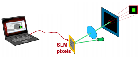
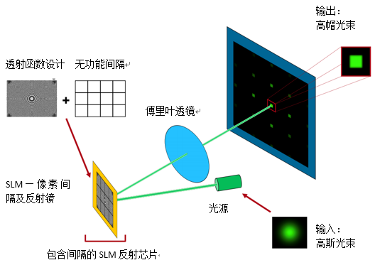
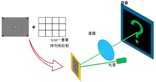
1. 系统细节 光源— 高斯光束 组件— 反射型空间光调制器组件及后续的2f系统 探测器— 视觉感知的仿真— 电磁场分布 建模/设计— 场追迹: 一个SLM像素阵列处光传播的仿真,仿真中包括了SLM像素间无功能间隔引起的衍射效应。 2. 系统说明
 3. 模拟 & 设计结果
 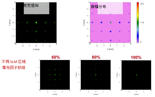 4. 总结
4. 总结考虑SLM像素间隔来研究空间光调制器的性能。 第1步将像素间隔引入到一个先前设计的用于光束整形的SLM透射函数。 第2步分析不同区域填充因子的对性能的影响。 产生的衍射效应对SLM的光学功能以及效率具有重大影响。
应用示例详细内容
系统参数
1. 该应用实例的内容
 2. 设计&仿真任务
由于制造和技术的原因,像素之间存在非功能间隔。这种典型的间隔会产生衍射效应,从而影响SLM的光学性能,并在接下来的工作中对其进行研究。
 3. 参数:输入近乎平行的激光束
 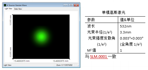 4. 参数:SLM像素阵列
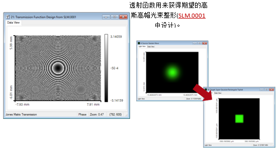 5. 参数:SLM像素阵列
 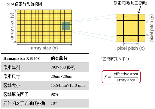 应用示例详细内容
 仿真&结果
1. VirtualLab能够模拟具有间隔的SLM 由于可以嵌入组件,VirtualLab可以轻松的实现反射系统(如反射镜,2f系统等)。 内置的SLM模式可以实现从简单透射函数到包含像素和间隔的阵列的自动转换。
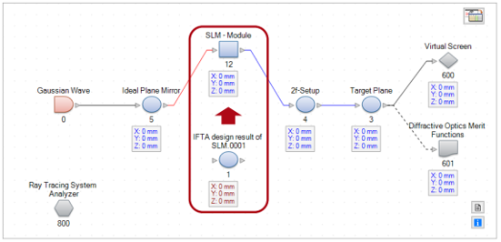 2. VirtualLab的SLM模块
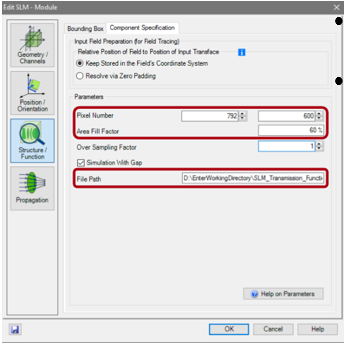
为设置像素阵列,必须输入像素阵列尺寸和区域填充因子。 必须设置所设计的SLM透射函数。因此,需要输入文件SLM_Transmission_Function.ca2的路径。 3. SLM的光学功能
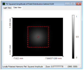
在第一步,我们可以研究SLM后的电磁场。 为此,将区域填充因子设置为60%。 首先,获得场(Ex方向)的振幅,分别显示了SLM像素及其间隔的影响。
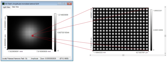 所用文件: SLM.0002_Diffraction_Pixels_SLM_01_Nearfield.lpd 此处,场(Ex方向)的(Wrapped)位相如下图所示,其中所有的间隔的相位值都为一个常数值。
 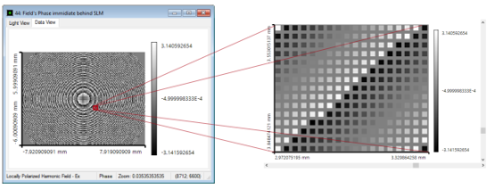 所用文件: SLM.0002_Diffraction_Pixels_SLM_02_2DGrating.lpd 4. 对比:光栅的光学功能 上述的像素效应可以用相似光学功能的2D周期结构的进行比较。 所示函数(Ex的振幅)相当于一个SLM,其像素提供一个常数位相函数。 通过这种光栅,能够将光衍射到几个衍射级次,衍射级次分布在x-和y-方向(由于二维光栅结构)。 级次越高振幅衰减越快,所以只有0级,1级以及2级贡献了主要的光强部分。 这意味着,对于SLM,我们所期望的光分布具有有较高的级次,其光强由区域填充因子决定。
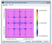 所用文件: SLM.0002_Diffraction_Pixels_SLM_02_2DGrating.lpd
5. 有间隔SLM的光学功能现在,基于像素阵列的区域填充因子,我们可以在傅里叶平面研究SLM的光学功能。
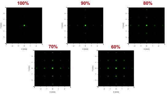 所用文件: SLM.0002_Diffraction_Pixels_SLM_03_2DGrating.lpd 下图显示了(Ex方向)光强分布,图中具有相同的振幅比率。
 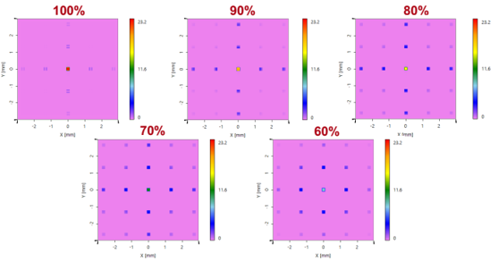 6. 减少计算工作量
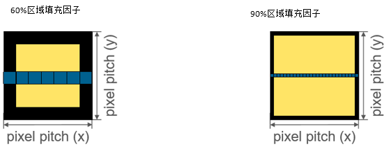
采样要求: 至少1个点的间隔(每边)。 如在有效区域,用户指定60%区域填充因子,模块在激活区域计算5×5点的等间距采样。 采样要求: 同样,至少1个点的间隔。 假设指定90%区域填充因子,模块计算25×25点的等间距采样。 随填充因子的增大,采样迅速增加。 为优化大填充因子条件下的计算工作量,减小相关阵列尺寸是非常有效的方法。 如果被照明区域小于阵列尺寸(标记区域包含光强的90%),这种简化是非常适用的。 如果只考虑标记的范围,仅计算SLM的320×320个像素即可(SLM模块自动删除了透射函数边界)。 通过优化,计算工作量减少了4.7倍。
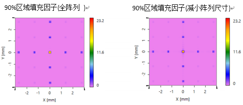 减小SLM阵列尺寸后计算所得的振幅分布几乎和全阵列一样。 7. 指定区域填充因子的仿真
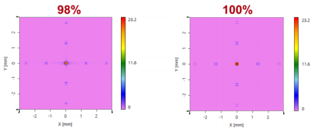
 由于间隔非常狭窄,Hamamatsu’s X10468 指定填充因子为98%,需要更多的采样点进行计算。 全阵列尺寸798×600像素将需要79992×60600个采样点,需要极高的计算量。 因此,可适当减小阵列尺寸到320×320像素,采样点数目为32320×32320。 在优化的帮助下,可对指定区域填充因子进行研究(该仿真仍需约256GB的内存)。
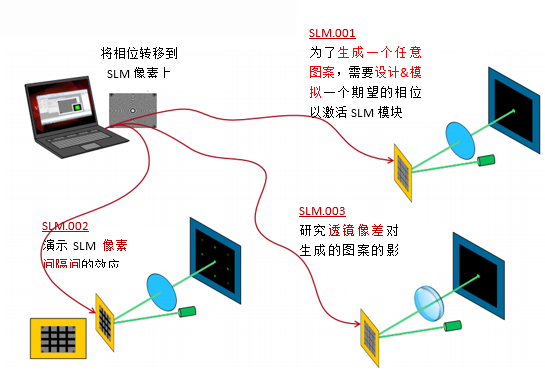
8. 总结考虑SLM像素间隔来研究空间光调制器的性能。 第1步将像素间隔引入到一个先前设计的用于光束整形的SLM透射函数。 第2步分析不同区域填充因子的对性能的影响。扩展阅读扩展阅读 开始视频- 光路图介绍 该应用示例相关文件:- SLM.0001:用于生成高帽光束的SLM位相调制器设计
- SLM.0003: 一个基于SLM光束整形系统的中透镜像差的研究
 我要赚赏金
我要赚赏金 STM32
STM32 MCU
MCU 通讯及无线技术
 物联网技术
物联网技术 电子DIY
电子DIY 板卡试用
板卡试用 基础知识
基础知识 软件与操作系统
 我爱生活
我爱生活 小e食堂
小e食堂

