简介:
现在的mcu 多核已经是很常见的了,对于多核调试时uart log 是一种使用比较常用的方式,对于多核我们可以给每一个核分配一个物理串口,如果资源比较紧张我么也可以和其他核共享一个串口来打印,我们本次的试验是使用后者的方式core0 核 core1 共享一个串口进行打印。
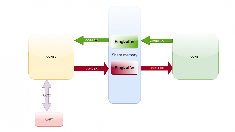
其实现思路是通过核间通信的share memory,在share memory 中分配一段内存中分配一段空间按照Ring buff 的方式进行存储,一端进行写入另一端读取,然后再CORE0中将数据转发到物理串口,对应的实现原理如下。

代码实现
按照上述share memory 中的数据管理方式本地定义如下数据结构
#define VUART_CORE0_RX_CORE1_TX_BUFFER_SIZE   256
#define VUART_CORE0_TX_CORE1_RX_BUFFER_SIZE   128

//#pragma pack(1)
struct virual_uart
{
    char magic[4];/* VURT */
    RingBuffer core0_rx_core1_tx;
    RingBuffer core0_tx_core1_rx;
    uint8_t core0_rx_core1_tx_buff[VUART_CORE0_RX_CORE1_TX_BUFFER_SIZE];
    uint8_t core0_tx_core1_rx_buff[VUART_CORE0_TX_CORE1_RX_BUFFER_SIZE];
};
按照上述流程,在CORE0 侧初始化share memory ,并将share memory 的地址信息通过和间通信的机制通知到CORE1,代码如下。
#ifdef APP_USING_VIRTUAL_UART
static struct virual_uart virual_uart0 @ "vuart0_sh_mem_section";


static void virual_uart_init(struct virual_uart * p_vuart)
{
    /* init memory buffer */
    memset((void *)p_vuart->core0_rx_core1_tx_buff,0,sizeof(p_vuart->core0_rx_core1_tx_buff));
    memset((void *)p_vuart->core0_tx_core1_rx_buff,0,sizeof(p_vuart->core0_tx_core1_rx_buff));

    /* init ringbuffer */
    RingBuffer_Init(&p_vuart->core0_rx_core1_tx,p_vuart->core0_rx_core1_tx_buff,sizeof(p_vuart->core0_rx_core1_tx_buff));
    RingBuffer_Init(&p_vuart->core0_tx_core1_rx,p_vuart->core0_tx_core1_rx_buff,sizeof(p_vuart->core0_tx_core1_rx_buff));

    /* init magic value */
    p_vuart->magic[0]  = 'V';
    p_vuart->magic[1]  = 'U';
    p_vuart->magic[2]  = 'R';
    p_vuart->magic[3]  = 'T';

}

#endif


int main(void)
{


    MAILBOX_Init(MAILBOX);
    NVIC_EnableIRQ(MAILBOX_IRQn);

#ifdef APP_USING_VIRTUAL_UART
    virual_uart_init(&virual_uart0);
    rt_kprintf("send to core1 virual uart addr %x.\n",(uint32_t)(&virual_uart0));
    MAILBOX_SetValue(MAILBOX,kMAILBOX_CM33_Core1,(uint32_t)(&virual_uart0));
#endif


}
CORE1 侧将对应的log 输出函数 本地使用的printf 底层IO接口输出写入到Ringbuff
size_t __write(int handle, const unsigned char *buffer, size_t size)
{

     while(MAILBOX_GetMutex(MAILBOX) == 0);


     RingBuffer_Write(&p_virtual_uart0->core0_rx_core1_tx,(uint8_t *)buffer,size);

     MAILBOX_SetMutex(MAILBOX);

     return size;
}
CORE0 侧读取对应的Ringbuff 并将数据转发至UART 物理层,对应代码如下。
int main(void)
{
    while (1)
    {
        uint8_t data;
        //rt_pin_write(LEDB_PIN, PIN_HIGH);    /* Set GPIO output 1 */
        //rt_thread_mdelay(500);               /* Delay 500mS */
        //rt_pin_write(LEDB_PIN, PIN_LOW);     /* Set GPIO output 0 */
        //rt_thread_mdelay(500);               /* Delay 500mS */
        while(MAILBOX_GetMutex(MAILBOX) == 0);

        while(RingBuffer_GetDataLength(&virual_uart0.core0_rx_core1_tx))
        {
            RingBuffer_Read(&virual_uart0.core0_rx_core1_tx,&data,1);
            rt_kprintf("%c",data);
        }

        MAILBOX_SetMutex(MAILBOX);

        rt_thread_mdelay(10);
    }
}
至此代码已经适配完成,在 CORE1 侧调用printf 函数验证虚拟串口的功能。
/*!
 * @brief Main function
 */
int main(void)
{

    while(p_virtual_uart0 == NULL);

    if(p_virtual_uart0->magic[0] == 'V' &&
       p_virtual_uart0->magic[1] == 'U' &&
       p_virtual_uart0->magic[2] == 'R' &&
       p_virtual_uart0->magic[3] == 'T')
    {
        printf("\r\n [core1] virtual uart init ok.\r\n");
    }

    /* Configure LED */
    LED_INIT();


    for (;;)
    {
        SDK_DelayAtLeastUs(500000U, SDK_DEVICE_MAXIMUM_CPU_CLOCK_FREQUENCY);
        LED_TOGGLE();
        printf("\r\n [core1] led toggle.\r\n");
    }

}
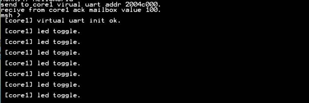
运行发现core0 和 core1 的log 都按照预期的在uart 上输出显示了,至此已经完成上述通过share memory 来虚拟串口显示log 的功能。


 我要赚赏金
我要赚赏金

