
要谢谢你呀
12楼
LED灯闪烁
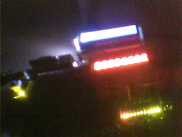
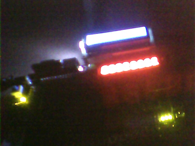
LED闪烁:
library ieee;
use ieee.std_logic_1164.all;
entity led is
port(clk: in std_logic;
ledout:out std_logic_vector(7 downto 0));
end entity;
architecture behave of led is
signal cnt: std_logic;
begin
process(clk)
begin
if clk'event and clk='1' then
cnt<=not cnt;
case cnt is
when '0'=>
ledout<="00000000";
when '1'=>
ledout<="11111111";
end case;
end if;
end process;
end behave;
分频:
library ieee;
use ieee.std_logic_1164.all;
use ieee.std_logic_unsigned.all;
entity clkdiv is
port(clk : in std_logic;
clkout : out std_logic);
end clkdiv;
architecture behave of clkdiv is
signal cnt : std_logic_vector(35 downto 0);
begin
process(clk)
begin
if clk'event and clk = '1' then
if cnt > 19999999 then
cnt <= (others => '0');
clkout <= '0';
elsif cnt > 9999999 then
clkout <= '1';
cnt <= cnt + 1;
else
cnt <= cnt + 1;
end if;
end if;
end process;
end behave;
13楼
首先提出我发现的一个问题:
在做拨码开关时,程序写好了,编译,没有错误,但在分配管脚时使用108管脚时出错了,原因是108管脚时复用功能引脚,错误提示是:
Error:
Can't place multiple pins assigned to pin location Pin_108 (IOC_X28_Y2_N0)
Info: Pin b[1] is assigned to pin location Pin_108 (IOC_X28_Y2_N0)
Info: Pin ~LVDS41p/nCEO~ is assigned to pin location Pin_108 (IOC_X28_Y2_N0)
由于上述原因,拨码开关的第二个管脚就没有使用到108脚,在分配管脚时不使用108管脚编译就没有错误了。具体怎样解决这个问题,我还不清楚,还得那位大虾指教一下。
此问题已有大侠解决:
http://forum.eepw.com.cn/thread/221279/1
拨码开关控制LED亮灭VHDL代码:
library ieee;
use ieee.std_logic_1164.all;
entity boma is
port(b:in std_logic_vector(7 downto 0);
d: out std_logic_vector(7 downto 0));
end entity ;
architecture behave of boma is
begin
process(b)
begin
d<=b;
end process;
end behave;
好简单的一个程序
14楼
读取按键信息:
思路比较简单,将按键的八位作为输入,并将他作为敏感信号,当有按键按下或是松开时时,触发敏感信号,将按键的键值输出给LED灯显示。按键按下,对应的LED灯亮,松开时对应的灯就灭了。
代码如下:
library ieee;
use ieee.std_logic_1164.all;
entity boma is
port(b:in std_logic_vector(7 downto 0);
d: out std_logic_vector(7 downto 0));
end entity ;
architecture behave of boma is
begin
process(b)
begin
d<=b;
end process;
end behave;
这段代码和拨码开关控制LED亮灭没有区别,有所不同的是在管脚分配时对应的管脚不一样而已。
15楼
附上代码:
use ieee.std_logic_unsigned.all;
--beep
entity ring is
port(clk: in std_logic;
n_rst:in std_logic;
beep: out std_logic);
end ring;
architecture behave of ring is
signal cnt:std_logic_vector(11 downto 0);
signal temp:std_logic;
begin
process(clk)
begin
if clk'event and clk='1' then
cnt<=cnt+1;
if cnt="111111111111" then
temp<=not temp;
beep<=temp;
end if;
end if;
end process;
end behave;
注意:如果下载sof文件测试的话,使用的是Y2
sof文件下载:
ring.rar
16楼
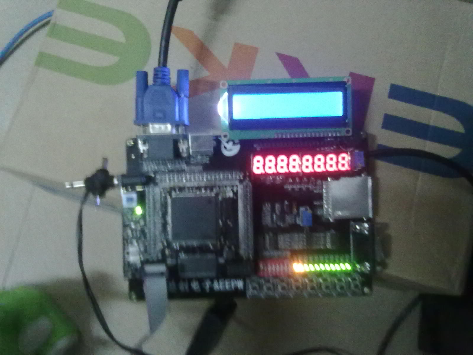
我电路板上使用的是Y2,但在做静态数码管显示时没有使用晶振,而是将按键的出入作为敏感信号,所以Y2好坏并不影响静态数码管的显示,但动态数码管显示时没有晶振就显示不了,我拿其他人的sof文件测试了,确实是晶振的问题,我重新焊接后,动态数码管就显示了相应的数字。我前后可是使用的同一个SOF文件。
对了,我还有个问题想问你,是不是FPGA外部不接晶振也可以照样工作呢,里面是不是内嵌了震荡电路?
对了,我还有个问题想问你,是不是FPGA外部不接晶振也可以照样工作呢,里面是不是内嵌了震荡电路?
19楼
串口收发通信:波特率为9600
使用Y2,有兴趣的可以下载sof文件去测试一下,使用数码管的地两位显示从串口发送过来的十六进制数,在上位机上我使用的是串口调试助手。例如,当从PC机发送0xff过来时,数码管也将显示ff。按键的key4-key7对应为向PC机发送数据的高4位,拨码开关的sw4-sw7对应发送数据的第四位。key0为串口收发通信的复位键,key1为发送数据控制键,即当按下一次key1键时,就从拨码开关和按键读取八位要发送的数据向PC机发送一次,按一次发送一次数据。
串口向下位机发送数据

此时上位机发送的是0x68,
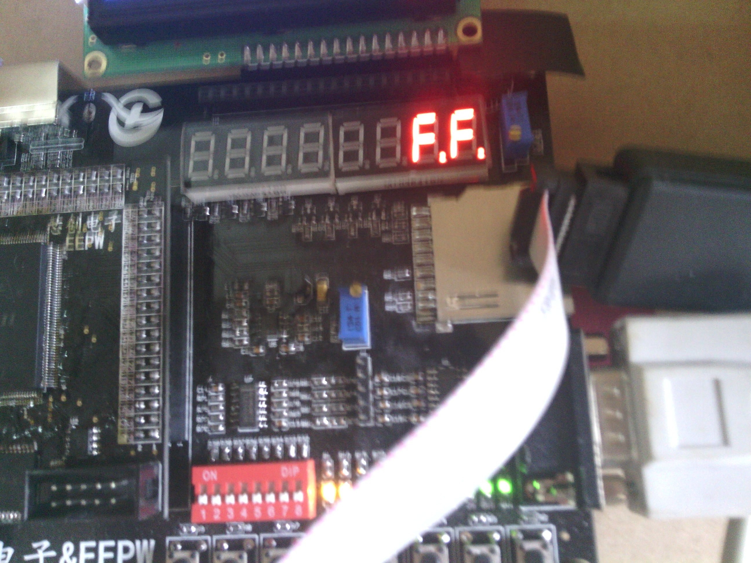
此时为0xff.
下位机向上位机发送数据,串口调试助手显示如下:
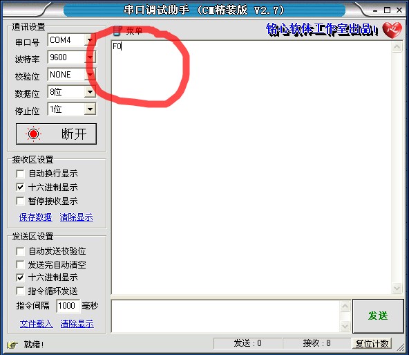
如图,此时拨码开关的高四位接地,按键的高四位为高(没有按下),按下一次key1,串口调试助手就收到数据并显示FO,如上图圈中的数据。
sof文件下载:
——回复可见内容——
使用Y2,有兴趣的可以下载sof文件去测试一下,使用数码管的地两位显示从串口发送过来的十六进制数,在上位机上我使用的是串口调试助手。例如,当从PC机发送0xff过来时,数码管也将显示ff。按键的key4-key7对应为向PC机发送数据的高4位,拨码开关的sw4-sw7对应发送数据的第四位。key0为串口收发通信的复位键,key1为发送数据控制键,即当按下一次key1键时,就从拨码开关和按键读取八位要发送的数据向PC机发送一次,按一次发送一次数据。
串口向下位机发送数据
此时上位机发送的是0x68,
此时为0xff.
下位机向上位机发送数据,串口调试助手显示如下:
如图,此时拨码开关的高四位接地,按键的高四位为高(没有按下),按下一次key1,串口调试助手就收到数据并显示FO,如上图圈中的数据。
sof文件下载:
——回复可见内容——
回复
 我要赚赏金打赏帖 我要赚赏金打赏帖 |
|
|---|---|
| 【S32K3XX】FlexCAN 模块配置使用被打赏¥30元 | |
| 【S32K3XX】FlexCAN RAM 资源分配整理被打赏¥25元 | |
| 【S32K3XX】IPCF 适配核间中断处理被打赏¥21元 | |
| 【S32K3XX】IPCF 核间通讯模块UNMANAGED方式使用被打赏¥29元 | |
| 片外存储Flash使用方法(Arduino IDE环境)被打赏¥22元 | |
| 三分钟快速上手ESP-NOW(ArduinoIDE环境)被打赏¥23元 | |
| 【S32K3XX】LPSPI参数配置说明被打赏¥21元 | |
| 在WT9932C61-TINY上实现超声波测距被打赏¥22元 | |
| 基于WT9932C61-TINY的环境构建及OLED屏驱动测试被打赏¥20元 | |
| 【S32K3XX】Core-to-Core 中断使用被打赏¥21元 | |
 STM32
STM32 MCU
MCU 通讯及无线技术
 物联网技术
物联网技术 电子DIY
电子DIY 板卡试用
板卡试用 基础知识
基础知识 软件与操作系统
 我爱生活
我爱生活 小e食堂
小e食堂

