
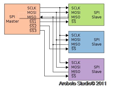
SPI接口
SPI(Serial Peripheral Interface)是由摩托罗拉公司提出的一种同步串行外设接口总线,它可以使MCU与各种外围设备以串行方式进行通信以及交换信息,总线采用3根或者4根数据线进行数据传输,常用的是4根线,即两条控制线(芯片选择cs和时钟sclk)以及两条数据线SDI和SDO。
SPI是一种高速、全双工、同步的通信总线。在摩托罗拉公司的SPI技术规范中,数据信号线SDIc称为MISO(主入从出),控制信号线SDO成为(主出从入),控制信号线CS称为SS(从属选择),将SCLK称为SCK(串行时钟)。在SPI通信中,数据是同步进行发送和接受的数据传输的时钟基于来自主处理器产生的时钟脉冲,摩托罗拉公司没有定义任何通用的SPI时钟规范。
SPI接口示意图:
SPI类及其成员函数
Arduino的SPI通信是通过SPIClass类实现的,使用SPIclass类能方便的将Arduino作为主设备与其他去从设备通信。SPIClass类提供了6个成员函数,如下:
- Begin()
- setBitorder()
- setClockDivider()
- setDataMode()
- Transfer()
- end()
Begin函数用于初始化SPI总线。
setBitorder的作用是在设置串行数据传输时先传输低位还是先传输高位,函数有一个type类型的参数bitOrder,有LSBFIRST和MSBFIRST两种类型可选。
setClockDivider 函数的作用是设置SPI串行通信的时钟,通信时钟由系统分频得到,分频可选2、4、8、16、32、64及128,有一个type类型的参数rate,有7种类型,对应7个分频值分别为SP_CLOCK_DIV2、
SP_CLOCK_DIV4、SP_CLOCK_DIV8、SP_CLOCK_DIV16、SP_CLOCK_DIV32、SP_CLOCK_DIV64、SP_CLOCK_DIV128,函数默认设置是SP_CLOCK_DIV4,设置SPI串行通信时候总为时钟的1/4.
setDataMode函数的作用是设置SPI数据模式,由于SPI通信中没有定义任何通用的时钟规范,所以在具体应用中有的在上升沿采样,有的在下降沿采样。
Transfer函数用来传输一个数据,由于SPI是一种全双工、同步的通信总线。所以传输一个数据实际会发送一个数据,同时接受一个数据。
End函数停止SPI总线的使用。
You must specify each pin you wish to use as CS for the SPI devices.
It is possible for the Due to automatically handle the chip selection between multiple devices sharing the SPI bus. Each device may have also different attribues such as speed and datamode.
If using multiple devices with different CS pins, you'll need to declare those pins in setup(). In the following example, there are two devices that share the SPI MISO, MOSI, and SCK pins. One device CS is attached to pin 4, the other to pin 10.
void setup(){
// initialize the bus for a device on pin 4
SPI.begin(4);
// initialize the bus for a device on pin 10
SPI.begin(10);
}
Once a pin has been declared as a CS pin, it's possible to change its default behaviors as well. For example, if the devices run at different clock speeds, the setup() may look like this :
void setup(){
// initialize the bus for the device on pin 4
SPI.begin(4);
// Set clock divider on pin 4 to 21
SPI.setClockDivider(4, 21);
// initialize the bus for the device on pin 10
SPI.begin(10);
// Set clock divider on pin 10 to 84
SPI.setClockDivider(10, 84);
}
A single byte transfer to a device on pin 4 could look like this :
void loop(){byte response = SPI.transfer(4, 0xFF);
} In the above, “0xFF” is sent to the SPI device on pin 4 and the data coming from MISO is saved inside the variableresponse The chip selection is handled automatically by the SPI controller, the transfer command implies the following:
- Select device by setting pin 4 to LOW
- Send 0xFF through the SPI bus and return the byte received
- Deselect device by setting pin 4 to HIGH
It's possible to send more than one byte in a transaction by telling the the transfer command to not deselect the SPI device after the transfer :
void loop(){//transfer 0x0F to the device on pin 10, keep the chip selected
SPI.transfer(10, 0xF0, SPI_CONTINUE);
//transfer 0x00 to the device on pin 10, keep the chip selected
SPI.transfer(10, 0×00, SPI_CONTINUE);
//transfer 0x00 to the device on pin 10, store byte received in response1, keep the chip selected
byte response1 = SPI.transfer(10, 0×00, SPI_CONTINUE);
//transfer 0x00 to the device on pin 10, store byte received in response2, deselect the chip
byte response2 = SPI.transfer(10, 0×00);
} The parameter SPI_CONTINUE ensures that chip selection is keep active between transfers. On the last transfer SPI_CONTINUE is not specified as it's the last byte transferred.
See the individual reference pages for setClockDivider(), setDataMode(), transfer(), setBitOrder() for proper syntax when using the extended methods.
NB : once SPI.begin() is called, the declared pin will not be available as a general purpose I/O pin
SD卡
SD卡体积小,价格便宜,因此在许多工业数据记录和家用电子产品中有越来越多的应用。Arduino可以通过SPI接口与之通信,进行诸如建立文件、删除文件、向文件中添加内容、修改文件等操作,这样采用Arduino配合SD卡可以开发数据记录设备。要想操作SD卡一定要包含SDMMC那个库。否则编译时提示出错。
SD卡的操作的函数
begin 初始化SD卡。
SDMMC.begin
或SDMMC.begin(int cspin)
cspin为片选信号。
insert插入状态
SDMMC.insert(bool ins)
exists 看文件是否存在
bool SDMMC.exists(const char* filename)
mkdir 建立子目录
bool SDMMC.mkdir(const char* pathname)
成功返true 失败false
open 打开文件
File SDMMC.open(const char* filename, FILE_MODE mode)
remove删除文件
bool SDMMC.remove(const char* filename)
rename给文件重新命名
bool SDMMC.rename(const char* oldname, const char* newname)
rmdir 删除子目录名
bool SDMMC.rmdir(const char* pathname)
回复
 我要赚赏金打赏帖 我要赚赏金打赏帖 |
|
|---|---|
| 片外存储Flash使用方法(Arduino IDE环境)被打赏¥22元 | |
| 三分钟快速上手ESP-NOW(ArduinoIDE环境)被打赏¥23元 | |
| 【S32K3XX】LPSPI参数配置说明被打赏¥21元 | |
| 在WT9932C61-TINY上实现超声波测距被打赏¥22元 | |
| 基于WT9932C61-TINY的环境构建及OLED屏驱动测试被打赏¥20元 | |
| 【S32K3XX】Core-to-Core 中断使用被打赏¥21元 | |
| 「AI编程记录--含源码」用一晚上的时间写一个esp32的示波器被打赏¥19元 | |
| STM32C0116DK开发探索记(3)被打赏¥30元 | |
| STM32C0116DK开发探索记(2)被打赏¥24元 | |
| STM32C0116DK开发探索记(1)被打赏¥29元 | |
 STM32
STM32 MCU
MCU 通讯及无线技术
 物联网技术
物联网技术 电子DIY
电子DIY 板卡试用
板卡试用 基础知识
基础知识 软件与操作系统
 我爱生活
我爱生活 小e食堂
小e食堂

