
ADC&RGB视频
/**
******************************************************************************
* @file EXTI/EXTI_Config/main.c
* @author MCD Application Team
* @version V3.5.0
* @date 08-April-2011
* @brief Main program body
******************************************************************************
* @attention
*
* THE PRESENT FIRMWARE WHICH IS FOR GUIDANCE ONLY AIMS AT PROVIDING CUSTOMERS
* WITH CODING INFORMATION REGARDING THEIR PRODUCTS IN ORDER FOR THEM TO SAVE
* TIME. AS A RESULT, STMICROELECTRONICS SHALL NOT BE HELD LIABLE FOR ANY
* DIRECT, INDIRECT OR CONSEQUENTIAL DAMAGES WITH RESPECT TO ANY CLAIMS ARISING
* FROM THE CONTENT OF SUCH FIRMWARE AND/OR THE USE MADE BY CUSTOMERS OF THE
* CODING INFORMATION CONTAINED HEREIN IN CONNECTION WITH THEIR PRODUCTS.
*
* <h2><center>© COPYRIGHT 2011 STMicroelectronics</center></h2>
******************************************************************************
*/
/* Includes ------------------------------------------------------------------*/
#include <stm32f10x.h>
#include "stm32_eval.h"
#include "delay.h"
#include <stdio.h>
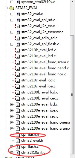
#include "spi_flash.h"
#define VREF 3.3
#define TxBufferSize1 (countof(TxBuffer1) - 1)
#define RxBufferSize1 (countof(TxBuffer1) - 1)
#define countof(a) (sizeof(a) / sizeof(*(a)))
#define BufferSize (countof(Tx_Buffer)-1)
typedef enum { FAILED = 0, PASSED = !FAILED} TestStatus;
#define FLASH_WriteAddress 0x00000
#define FLASH_ReadAddress FLASH_WriteAddress
#define FLASH_SectorToErase FLASH_WriteAddress
#define sFLASH_ID 0xEF3015 //W25X16
//#define sFLASH_ID 0xEF4015 //W25Q16
#define buff_size 16;
char rx_buff_count=0;
/* ???????? */
uint8_t Tx_Buffer[4096] ; //发送缓冲
uint8_t Rx_Buffer[BufferSize]; //接受缓冲
__IO uint32_t DeviceID = 0; //装置ID
__IO uint32_t FlashID = 0; //闪存ID
__IO TestStatus TransferStatus1 = FAILED; //状态测试
// ??????
void Delay(__IO uint32_t nCount);
TestStatus Buffercmp(uint8_t* pBuffer1, uint8_t* pBuffer2, uint16_t BufferLength);
/** @addtogroup STM32F10x_StdPeriph_Examples
* @{
*/
/** @addtogroup EXTI_Config
* @{
*/
/* Private typedef -----------------------------------------------------------*/
/* Private define ------------------------------------------------------------*/
/* Private macro -------------------------------------------------------------*/
/* Private variables ---------------------------------------------------------*/
GPIO_InitTypeDef GPIO_InitStructure;
USART_InitTypeDef USART_InitStructure;
USART_ClockInitTypeDef USART_ClockInitStructure;
char *int_to_string(int number,char *strnum)//整形数据转换为字符型
{
int j=0,i=0,n=0;
char temp;
while(number>0)
{
*(strnum+j)=number%10+48;
j++;
number=number/10;
n++;
}
for(i=0;i<n/2;i++)
{
temp=*(strnum+j+i-n);
*(strnum+j+i-n)=*(strnum+j-i-1);
*(strnum+j-i-1)=temp;
}
strnum[n]='\0';
return strnum;
}
void RCC_Configuration(void)
{
RCC_DeInit();
RCC_HSICmd(ENABLE); //使能HSI
while(RCC_GetFlagStatus(RCC_FLAG_HSIRDY) == RESET);
RCC_SYSCLKConfig(RCC_SYSCLKSource_HSI);
RCC_HSEConfig(RCC_HSE_OFF);
RCC_LSEConfig(RCC_LSE_OFF);
RCC_PLLConfig(RCC_PLLSource_HSI_Div2,RCC_PLLMul_9); // 72HMz
RCC_PLLCmd(ENABLE);
while(RCC_GetFlagStatus(RCC_FLAG_PLLRDY) == RESET);
RCC_ADCCLKConfig(RCC_PCLK2_Div4);
RCC_PCLK2Config(RCC_HCLK_Div1);
RCC_PCLK1Config(RCC_HCLK_Div2);
RCC_HCLKConfig(RCC_SYSCLK_Div1);
RCC_SYSCLKConfig(RCC_SYSCLKSource_PLLCLK);
while(RCC_GetSYSCLKSource() != 0x08)
//SystemInit();
RCC_APB2PeriphClockCmd(RCC_APB2Periph_GPIOD|RCC_APB2Periph_AFIO, ENABLE);
GPIO_PinRemapConfig(GPIO_Remap_SWJ_JTAGDisable,ENABLE);//disable JTAG
RCC_APB2PeriphClockCmd(RCC_APB2Periph_GPIOD|RCC_APB2Periph_AFIO, ENABLE);
GPIO_PinRemapConfig(GPIO_Remap_SWJ_JTAGDisable,ENABLE);//disable JTAG
GPIO_InitStructure.GPIO_Pin = GPIO_Pin_2;
GPIO_InitStructure.GPIO_Speed = GPIO_Speed_50MHz;
GPIO_InitStructure.GPIO_Mode = GPIO_Mode_Out_PP;
GPIO_Init(GPIOD, &GPIO_InitStructure);
GPIO_ResetBits(GPIOD,GPIO_Pin_2);
RCC_APB2PeriphClockCmd(RCC_APB2Periph_GPIOC|RCC_APB2Periph_AFIO, ENABLE);
GPIO_PinRemapConfig(GPIO_Remap_SWJ_JTAGDisable,ENABLE);//disable JTAG
GPIO_InitStructure.GPIO_Pin = GPIO_Pin_0|GPIO_Pin_1|GPIO_Pin_2|GPIO_Pin_3|GPIO_Pin_4|GPIO_Pin_5|GPIO_Pin_6|GPIO_Pin_7;
GPIO_InitStructure.GPIO_Speed = GPIO_Speed_50MHz;
GPIO_InitStructure.GPIO_Mode = GPIO_Mode_Out_PP;
GPIO_Init(GPIOC, &GPIO_InitStructure);
GPIO_SetBits(GPIOC,GPIO_Pin_0|GPIO_Pin_1|GPIO_Pin_2|GPIO_Pin_3|GPIO_Pin_4|GPIO_Pin_5|GPIO_Pin_6|GPIO_Pin_7);
RCC_APB1PeriphClockCmd(RCC_APB1Periph_TIM2, ENABLE);
}
void USART_int(long BaudRate)
{
RCC_APB2PeriphClockCmd(RCC_APB2Periph_GPIOA|RCC_APB2Periph_USART1,ENABLE);
GPIO_InitStructure.GPIO_Pin = GPIO_Pin_9;
GPIO_InitStructure.GPIO_Speed = GPIO_Speed_50MHz;
GPIO_InitStructure.GPIO_Mode = GPIO_Mode_AF_PP;
GPIO_Init(GPIOA, &GPIO_InitStructure);
/* PA10 USART1_Rx */
GPIO_InitStructure.GPIO_Pin = GPIO_Pin_10;
GPIO_InitStructure.GPIO_Mode = GPIO_Mode_IN_FLOATING;
GPIO_Init(GPIOA, &GPIO_InitStructure);
/* USARTx configured as follow:
- BaudRate = 115200 baud
- Word Length = 8 Bits
- One Stop Bit
- No parity
- Hardware flow control disabled (RTS and CTS signals)
- Receive and transmit enabled
*/
USART_InitStructure.USART_BaudRate = BaudRate;//??????
USART_InitStructure.USART_WordLength = USART_WordLength_8b;//???????8bit
USART_InitStructure.USART_StopBits = USART_StopBits_1;//????1
USART_InitStructure.USART_Parity = USART_Parity_No;//????
USART_InitStructure.USART_HardwareFlowControl = USART_HardwareFlowControl_None;//??????none
USART_InitStructure.USART_Mode = USART_Mode_Rx | USART_Mode_Tx;//??????????
USART_ClockInitStructure.USART_Clock = USART_Clock_Disable;
USART_ClockInitStructure.USART_CPOL = USART_CPOL_Low;
USART_ClockInitStructure.USART_CPHA = USART_CPHA_2Edge;
USART_ClockInitStructure.USART_LastBit = USART_LastBit_Disable;
USART_ClockInit(USART1, &USART_ClockInitStructure);
USART_Init(USART1, &USART_InitStructure);
USART_Cmd(USART1, ENABLE);
USART_ITConfig(USART1, USART_IT_RXNE, ENABLE);
USART_Cmd(USART1, ENABLE);
}
TestStatus Buffercmp(uint8_t* pBuffer1, uint8_t* pBuffer2, uint16_t BufferLength)
{
while(BufferLength--)
{
if(*pBuffer1 != *pBuffer2)
{
return FAILED;
}
pBuffer1++;
pBuffer2++;
}
return PASSED;
}
void Delay(__IO uint32_t nCount)
{
for(; nCount != 0; nCount--);
}
void ADC_CONFIG(){
ADC_InitTypeDef ADC_InitStructure;
#if defined (STM32F10X_LD_VL) || defined (STM32F10X_MD_VL) || defined (STM32F10X_HD_VL)
/* ADCCLK = PCLK2/2 */
RCC_ADCCLKConfig(RCC_PCLK2_Div2);
#else
/* ADCCLK = PCLK2/4 */
RCC_ADCCLKConfig(RCC_PCLK2_Div4);
#endif
ADC_DeInit(ADC1);
/* Enable ADC1 and GPIOC clock */
RCC_APB2PeriphClockCmd(RCC_APB2Periph_ADC1 | RCC_APB2Periph_GPIOB, ENABLE);
/* Configure PB0 (ADC Channel14) as analog input -------------------------*/
GPIO_InitStructure.GPIO_Pin = GPIO_Pin_0;
GPIO_InitStructure.GPIO_Mode = GPIO_Mode_AIN;
GPIO_Init(GPIOB, &GPIO_InitStructure);
/* ADC1 configuration ------------------------------------------------------*/
ADC_InitStructure.ADC_Mode = ADC_Mode_Independent;
ADC_InitStructure.ADC_ScanConvMode = ENABLE;
ADC_InitStructure.ADC_ContinuousConvMode = ENABLE;
ADC_InitStructure.ADC_ExternalTrigConv = ADC_ExternalTrigConv_None;
ADC_InitStructure.ADC_DataAlign = ADC_DataAlign_Right;
ADC_InitStructure.ADC_NbrOfChannel = 1;
ADC_Init(ADC1, &ADC_InitStructure);
/* Enable ADC1 DMA */
ADC_DMACmd(ADC1, ENABLE);
/* Enable ADC1 */
ADC_Cmd(ADC1, ENABLE);
}
int Get_ADC(){
/* ADC1 regular channel configuration */
ADC_RegularChannelConfig(ADC1, ADC_Channel_8, 1, ADC_SampleTime_55Cycles5);
/* Enable ADC1 reset calibration register */
ADC_ResetCalibration(ADC1);
/* Check the end of ADC1 reset calibration register */
while(ADC_GetResetCalibrationStatus(ADC1));
/* Start ADC1 calibration */
ADC_StartCalibration(ADC1);
/* Check the end of ADC1 calibration */
while(ADC_GetCalibrationStatus(ADC1));
/* Start ADC1 Software Conversion */
ADC_SoftwareStartConvCmd(ADC1, ENABLE);
return ADC_GetConversionValue(ADC1);
}
void SPI_TEST()
{
int i=0;
int ADValue = 0;
float Volt=0.00;
char shuzu[100];
for(i=0;i<5;i++)
{
ADValue = Get_ADC();
Volt = VREF*ADValue/4095;
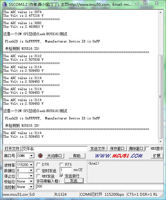
printf("===============================\r\n");
printf("The ADC value is:%d\r\n",ADValue);
printf("The Volt is:%f V\r\n",Volt);
delay_ms(500);
}
printf("\r\n这是一个2M SPI总线flash(W25X16)测试 \r\n");
SPI_FLASH_Init();
/* Get SPI Flash Device ID */
DeviceID = SPI_FLASH_ReadDeviceID();
Delay( 200 );
/* Get SPI Flash ID */
FlashID = SPI_FLASH_ReadID();
printf("\r\n FlashID is 0x%X, Manufacturer Device ID is 0x%X\r\n", FlashID, DeviceID);
/* Check the SPI Flash ID */
if (FlashID == sFLASH_ID) /* #define sFLASH_ID 0xEF3015 */
{
printf("\r\n 检测到华邦flash W25X16 !\r\n");
/* Erase SPI FLASH Sector to write on */
SPI_FLASH_SectorErase(FLASH_SectorToErase);
/*写缓存并发送*/
SPI_FLASH_BufferWrite(Tx_Buffer, FLASH_WriteAddress, BufferSize);
printf("\r\n写入的数据是:%s \r\t", Tx_Buffer);
/* 读出刚才写入的数据*/
SPI_FLASH_BufferRead(Rx_Buffer, FLASH_ReadAddress, BufferSize);
printf("\r\n读出的数据是:%s \r\n", Rx_Buffer);
/* ????????????????? */
TransferStatus1 = Buffercmp(Tx_Buffer, Rx_Buffer, BufferSize);
if( PASSED == TransferStatus1 )
{
printf("\r\n 2M SPI总线flash(W25X16)测试成功!\n\r");
}
else
{
printf("\r\n 2M SPI总线flash(W25X16)测试失败!\n\r");
}
}// if (FlashID == sFLASH_ID)
else
{
printf("\r\n 未检测到 W25X16 ID!\n\r");
}
SPI_Flash_PowerDown();
printf("\r\n=================================================\n\r");
}
/* Private functions ---------------------------------------------------------*/
/**
* @brief Main program.
* @param None
* @retval None
*/
int main(void)
{
/*!< At this stage the microcontroller clock setting is already configured,
this is done through SystemInit() function which is called from startup
file (startup_stm32f10x_xx.s) before to branch to application main.
To reconfigure the default setting of SystemInit() function, refer to
system_stm32f10x.c file
*/
/* System Clocks Configuration */
RCC_Configuration();
USART_int(115200);
ADC_CONFIG();
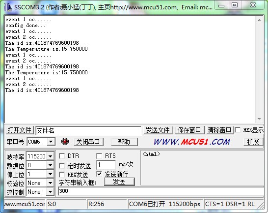
printf(" config done...\r\n");
Get_ADC();
delay_ms(1000);
while(1)
{
SPI_TEST();
delay_ms(1000);
}
}
#ifdef USE_FULL_ASSERT
/**
* @brief Reports the name of the source file and the source line number
* where the assert_param error has occurred.
* @param file: pointer to the source file name
* @param line: assert_param error line source number
* @retval None
*/
void assert_failed(uint8_t* file, uint32_t line)
{
/* User can add his own implementation to report the file name and line number,
ex: printf("Wrong parameters value: file %s on line %d\r\n", file, line) */
/* Infinite loop */
while (1)
{
}
}
#endif
/**
* @}
*/
/**
* @}
*/
#ifdef __GNUC__
/* With GCC/RAISONANCE, small printf (option LD Linker->Libraries->Small printf
set to 'Yes') calls __io_putchar() */
#define PUTCHAR_PROTOTYPE int __io_putchar(int ch)
#else
#define PUTCHAR_PROTOTYPE int fputc(int ch, FILE *f)
#endif /* __GNUC__ */
/**
* @brief Retargets the C library printf function to the USART.
* @param None
* @retval None
*/
PUTCHAR_PROTOTYPE
{
/* Place your implementation of fputc here */
/* e.g. write a character to the USART */
USART_SendData(EVAL_COM1, (uint8_t) ch);
/* Loop until the end of transmission */
while (USART_GetFlagStatus(EVAL_COM1, USART_FLAG_TC) == RESET)
{}
return ch;
}
#ifdef USE_FULL_ASSERT
/**
* @brief Reports the name of the source file and the source line number
* where the assert_param error has occurred.
* @param file: pointer to the source file name
* @param line: assert_param error line source number
* @retval None
*/
void assert_failed(uint8_t* file, uint32_t line)
{
/* User can add his own implementation to report the file name and line number,
ex: printf("Wrong parameters value: file %s on line %d\r\n", file, line) */
/* Infinite loop */
while (1)
{
}
}
#endif
只是简单的改了下老师的代码
/**
  ******************************************************************************
  * @file    EXTI/EXTI_Config/main.c
  * @author  MCD Application Team
  * @version V3.5.0
  * @date    08-April-2011
  * @brief   Main program body
  ******************************************************************************
  * @attention
  *
  * THE PRESENT FIRMWARE WHICH IS FOR GUIDANCE ONLY AIMS AT PROVIDING CUSTOMERS
  * WITH CODING INFORMATION REGARDING THEIR PRODUCTS IN ORDER FOR THEM TO SAVE
  * TIME. AS A RESULT, STMICROELECTRONICS SHALL NOT BE HELD LIABLE FOR ANY
  * DIRECT, INDIRECT OR CONSEQUENTIAL DAMAGES WITH RESPECT TO ANY CLAIMS ARISING
  * FROM THE CONTENT OF SUCH FIRMWARE AND/OR THE USE MADE BY CUSTOMERS OF THE
  * CODING INFORMATION CONTAINED HEREIN IN CONNECTION WITH THEIR PRODUCTS.
  *
  *

	© COPYRIGHT 2011 STMicroelectronics

******************************************************************************
  */

/* Includes ------------------------------------------------------------------*/
#include "stm32f10x.h"
#include "stm32_eval.h"
#include "delay.h"
#include
volatile int flag;
#define Set_B20()	 GPIO_SetBits(GPIOC, GPIO_Pin_12) //上拉关闭PC12
#define Reset_B20()	 GPIO_ResetBits(GPIOC, GPIO_Pin_12)//下拉打开PC12
#define Read_B20()	 GPIO_ReadInputDataBit(GPIOC,GPIO_Pin_12)//读PC12状态
unsigned char Error_Flag=0;
unsigned char zf=0;
void SysTick_Configuration(void)
{
  /* Setup SysTick Timer for 10 msec interrupts  */
  if (SysTick_Config(48000))                //SysTick配置48000/48ms=1ms
  {
    /* Capture error */
    while (1);
  }
 /* Configure the SysTick handler priority */
  NVIC_SetPriority(SysTick_IRQn, 0x0);                       //SysTick中断优先级
}


/** @addtogroup STM32F10x_StdPeriph_Examples
  * @{
  */

/** @addtogroup EXTI_Config
  * @{
  */

/* Private typedef -----------------------------------------------------------*/
/* Private define ------------------------------------------------------------*/
/* Private macro -------------------------------------------------------------*/
/* Private variables ---------------------------------------------------------*/
GPIO_InitTypeDef   GPIO_InitStructure;
USART_InitTypeDef USART_InitStructure;
USART_ClockInitTypeDef USART_ClockInitStructure;

void RCC_Configuration(void)
{
  RCC_DeInit(); //将外设RCC重新设为默认值

  RCC_HSICmd(ENABLE);//使能HSI高速内部时钟 8MHZ
  while(RCC_GetFlagStatus(RCC_FLAG_HSIRDY) == RESET);  //当SHI晶振就绪则重新设定

  RCC_SYSCLKConfig(RCC_SYSCLKSource_HSI);//设置系统时钟,时钟源为HSI

  RCC_HSEConfig(RCC_HSE_OFF);//设置外部高速晶振,HSE晶振OFF
  RCC_LSEConfig(RCC_LSE_OFF); //设置外部低速晶振,LSE晶振OFF
	   /******配置PLL时钟频率为48MHZ*******/
  RCC_PLLConfig(RCC_PLLSource_HSI_Div2,RCC_PLLMul_6); //   RCC_PLLMul_ 即设置PLL时钟频率为 6*8 MHz

  RCC_PLLCmd(ENABLE);//使能PLL
  while(RCC_GetFlagStatus(RCC_FLAG_PLLRDY) == RESET);//PLL就绪
  RCC_ADCCLKConfig(RCC_PCLK2_Div4);//  ADC时钟=PCLK/2
  RCC_PCLK2Config(RCC_HCLK_Div1);//  APB2时钟=HCLK
  RCC_PCLK1Config(RCC_HCLK_Div2);// APB1时钟=HCLK/2
  RCC_HCLKConfig(RCC_SYSCLK_Div1);//  AHB时钟=系统时钟
  RCC_SYSCLKConfig(RCC_SYSCLKSource_PLLCLK); // 选择PLL为系统时钟
  while(RCC_GetSYSCLKSource() != 0x08);//当PLL不是系统时钟


//	SystemInit();

	RCC_APB2PeriphClockCmd(RCC_APB2Periph_GPIOD|RCC_APB2Periph_AFIO, ENABLE);
 GPIO_PinRemapConfig(GPIO_Remap_SWJ_JTAGDisable,ENABLE);//disable JTAG
RCC_APB2PeriphClockCmd(RCC_APB2Periph_GPIOD|RCC_APB2Periph_AFIO, ENABLE);
 GPIO_PinRemapConfig(GPIO_Remap_SWJ_JTAGDisable,ENABLE);//disable JTAG
  GPIO_InitStructure.GPIO_Pin = GPIO_Pin_2;
  GPIO_InitStructure.GPIO_Speed = GPIO_Speed_50MHz;
  GPIO_InitStructure.GPIO_Mode = GPIO_Mode_Out_PP;
  GPIO_Init(GPIOD, &GPIO_InitStructure);
	GPIO_ResetBits(GPIOD,GPIO_Pin_2);
	RCC_APB2PeriphClockCmd(RCC_APB2Periph_GPIOC|RCC_APB2Periph_AFIO, ENABLE);
 GPIO_PinRemapConfig(GPIO_Remap_SWJ_JTAGDisable,ENABLE);//disable JTAG
  GPIO_InitStructure.GPIO_Pin = GPIO_Pin_0|GPIO_Pin_1|GPIO_Pin_2|GPIO_Pin_3|GPIO_Pin_4|GPIO_Pin_5|GPIO_Pin_6|GPIO_Pin_7;
  GPIO_InitStructure.GPIO_Speed = GPIO_Speed_50MHz;
  GPIO_InitStructure.GPIO_Mode = GPIO_Mode_Out_PP;
  GPIO_Init(GPIOC, &GPIO_InitStructure);
	GPIO_SetBits(GPIOC,GPIO_Pin_0|GPIO_Pin_1|GPIO_Pin_2|GPIO_Pin_3|GPIO_Pin_4|GPIO_Pin_5|GPIO_Pin_6|GPIO_Pin_7);
	  RCC_APB1PeriphClockCmd(RCC_APB1Periph_TIM2, ENABLE);//使能TIM2时钟
}

void USART_int(long BaudRate)
{
	RCC_APB2PeriphClockCmd(RCC_APB2Periph_GPIOA|RCC_APB2Periph_USART1,ENABLE);
       GPIO_InitStructure.GPIO_Pin = GPIO_Pin_9;
    GPIO_InitStructure.GPIO_Speed = GPIO_Speed_50MHz;
    GPIO_InitStructure.GPIO_Mode = GPIO_Mode_AF_PP;
    GPIO_Init(GPIOA, &GPIO_InitStructure);
    /* PA10 USART1_Rx  */
    GPIO_InitStructure.GPIO_Pin = GPIO_Pin_10;
    GPIO_InitStructure.GPIO_Mode = GPIO_Mode_IN_FLOATING;
    GPIO_Init(GPIOA, &GPIO_InitStructure);
  /* USARTx configured as follow:
        - BaudRate = 115200 baud
        - Word Length = 8 Bits
        - One Stop Bit
        - No parity
        - Hardware flow control disabled (RTS and CTS signals)
        - Receive and transmit enabled
  */
  USART_InitStructure.USART_BaudRate = BaudRate;//??????
  USART_InitStructure.USART_WordLength = USART_WordLength_8b;//???????8bit
  USART_InitStructure.USART_StopBits = USART_StopBits_1;//????1
  USART_InitStructure.USART_Parity = USART_Parity_No;//????
  USART_InitStructure.USART_HardwareFlowControl = USART_HardwareFlowControl_None;//??????none
  USART_InitStructure.USART_Mode = USART_Mode_Rx | USART_Mode_Tx;//??????????
	USART_ClockInitStructure.USART_Clock = USART_Clock_Disable;
    USART_ClockInitStructure.USART_CPOL = USART_CPOL_Low;
    USART_ClockInitStructure.USART_CPHA = USART_CPHA_2Edge;
    USART_ClockInitStructure.USART_LastBit = USART_LastBit_Disable;
    USART_ClockInit(USART1, &USART_ClockInitStructure);
  USART_Init(USART1, &USART_InitStructure);
  USART_Cmd(USART1, ENABLE);
	USART_ITConfig(USART1, USART_IT_RXNE, ENABLE);
 USART_Cmd(USART1, ENABLE);
}

void delay_18b20(u32 nus) //18b20按照严格的时序工作,专属延时
{
	u16 i;
	while(nus--)
		for(i=12;i>0;i--);
}


void Init18B20(void)  //18B20初始化
{
   u8 aa=0;
   u8 count =0;
	RCC_APB2PeriphClockCmd(RCC_APB2Periph_GPIOC, ENABLE);//使能PC时钟
  GPIO_InitStructure.GPIO_Pin = GPIO_Pin_12;//选择PC12
  GPIO_InitStructure.GPIO_Mode = GPIO_Mode_Out_OD;//开漏输出
  GPIO_Init(GPIOC, &GPIO_InitStructure);
   Set_B20() ; //拉高
   delay_18b20(1);  //复位时需要至少480us的低电平,当18b20接收到此信号后会回发芯片一个存在脉冲
   Reset_B20(); //拉低
   delay_18b20(480);
   Set_B20();//拉高
   delay_18b20(480);

	count=0;  //读取18B20的温度 赋值给aa

	 /*   校验读取值,错误次数大于99才报错 */
	aa=Read_B20();
    while(!aa && count<100)
   {
   	aa=Read_B20();
	count++;
   }
   if(count>=99) //次数大于99次,那么报错,标志位为1
   		Error_Flag=1;
	else
		Error_Flag=0;   //次数未达到99次,正常工作
}

unsigned char Read18B20(void)//读取18B20的一个字节
{
unsigned char i=0;
unsigned char date=0;
u8 tempp;
   for(i=8;i>0;i--)//按位读取,读取一个字需要循环8次
   {

   Reset_B20();//拉低电平,读数
   date>>=1;//右移一位
   delay_18b20(1);
   Set_B20();  //拉高电平,关闭
    delay_18b20(1);
   tempp=Read_B20();//读取温度值

   if(tempp)//若读取到的值非0
   		date|=0x80; //将date的最高位置1  1000 0000   然后右移,每次最高位由0变1,使8位全部传递完毕 0xff = 1111 1111
	delay_18b20(60);
	}
	return(date);
}
void Write18B20(unsigned char date)//写入数据
{
	unsigned char i=0;

	for (i=8; i>0; i--)
	{
		Reset_B20(); //置低电平
		delay_18b20(1);
		if(date & 0x01)			 //如果date最低位为1
		{
			Set_B20();//置高电平
		}
		else
		{	Reset_B20();}
		delay_18b20(60);
		date>>=1; 	 //date右移一位
		 Set_B20();//置高电平
		 delay_18b20(1);
	}
	delay_18b20(15);
}

 float Read_T()//读取温度值
{
		unsigned char TUp,TDown;
	unsigned char fTemp;
	u8 TT=0;

	 float Temp = 0;
	Init18B20();//1820初始化
	Write18B20(0xcc); 	 //不提供64位ROM编码使用存储器
	Write18B20(0x44); 	 //启动一次温度转换
	Init18B20();//1820初始化
	Write18B20(0xcc); 	//不提供64位ROM编码使用存储器
	Write18B20(0xbe); 	 //从字节0开始读取暂存器内容
	  /*两次读取温度*/
	TDown = Read18B20();
	TUp = Read18B20();

	if(TUp>0x7f)      //  如果TUp的值大于最大值(11111111)bin
	{
		TDown=~TDown;   //TDown取反
		TUp=~TUp+1; //TUp取反加一
		TUp/=8;		      //TUp除以8
		zf=1;         //zf标志位置1
 	}
	else
		zf=0;
	fTemp=TDown&0x0f;		//TDown保留后四位,赋值给fTemp
	TUp<<=4;//TUp左移四位,舍去高四位
	TDown>>=4;//TDown右移四位,舍去低四位
	TT=TUp|TDown;//TUp与TDown合并 赋值给TT
	Temp=TT+(float)fTemp/16;
	return(Temp);
}
int main(void)
{
	 int i;  	unsigned char ID[8];
  /*!< At this stage the microcontroller clock setting is already configured,
       this is done through SystemInit() function which is called from startup
       file (startup_stm32f10x_xx.s) before to branch to application main.
       To reconfigure the default setting of SystemInit() function, refer to
       system_stm32f10x.c file
     */

  /* System Clocks Configuration */
  RCC_Configuration();
USART_int(115200);
	Init18B20();//初始化18B20
	SysTick_Configuration();//系统滴答时钟配置

	printf(" config done...\r\n");
 Write18B20(0x33);//此命令获取18B20的ID
	 for(i=0;i<8;i++)//用一个8位的数组保存id值
    {
        ID[i]=Read18B20();
    }
	delay_ms(1000);

	while(1)
	{
		if(flag == 500){
			printf("The Temperature is:%f\r\n",Read_T());//500us读一次温度
}
  if(flag == 300){         //300us读一次id
              printf("The id is:");
                for(i=0;i<8;i++)
          {
                printf("%u",ID[i]);
                    if(i==7){printf("\r\n");    }
        }
      }
}
}
#ifdef  USE_FULL_ASSERT

/**
  * @brief  Reports the name of the source file and the source line number
  *         where the assert_param error has occurred.
  * @param  file: pointer to the source file name
  * @param  line: assert_param error line source number
  * @retval None
  */
void assert_failed(uint8_t* file, uint32_t line)
{
  /* User can add his own implementation to report the file name and line number,
     ex: printf("Wrong parameters value: file %s on line %d\r\n", file, line) */

  /* Infinite loop */
  while (1)
  {
  }
}

#endif

/**
  * @}
  */

/**
  * @}
  */

#ifdef __GNUC__
  /* With GCC/RAISONANCE, small printf (option LD Linker->Libraries->Small printf
     set to 'Yes') calls __io_putchar() */
  #define PUTCHAR_PROTOTYPE int __io_putchar(int ch)
#else
  #define PUTCHAR_PROTOTYPE int fputc(int ch, FILE *f)
#endif /* __GNUC__ */
/**
  * @brief  Retargets the C library printf function to the USART.
  * @param  None
  * @retval None
  */
PUTCHAR_PROTOTYPE
{
  /* Place your implementation of fputc here */
  /* e.g. write a character to the USART */
  USART_SendData(EVAL_COM1, (uint8_t) ch);

  /* Loop until the end of transmission */
  while (USART_GetFlagStatus(EVAL_COM1, USART_FLAG_TC) == RESET)
  {}

  return ch;
}

#ifdef  USE_FULL_ASSERT

/**
  * @brief  Reports the name of the source file and the source line number
  *         where the assert_param error has occurred.
  * @param  file: pointer to the source file name
  * @param  line: assert_param error line source number
  * @retval None
  */
void assert_failed(uint8_t* file, uint32_t line)
{
  /* User can add his own implementation to report the file name and line number,
     ex: printf("Wrong parameters value: file %s on line %d\r\n", file, line) */

  /* Infinite loop */
  while (1)
  {
  }
}


	#endif


	注意一下添加几个头文件
 我要赚赏金打赏帖 我要赚赏金打赏帖 |
|
|---|---|
| 【S32K3XX】FlexCAN 模块配置使用被打赏¥30元 | |
| 【S32K3XX】FlexCAN RAM 资源分配整理被打赏¥25元 | |
| 【S32K3XX】IPCF 适配核间中断处理被打赏¥21元 | |
| 【S32K3XX】IPCF 核间通讯模块UNMANAGED方式使用被打赏¥29元 | |
| 片外存储Flash使用方法(Arduino IDE环境)被打赏¥22元 | |
| 三分钟快速上手ESP-NOW(ArduinoIDE环境)被打赏¥23元 | |
| 【S32K3XX】LPSPI参数配置说明被打赏¥21元 | |
| 在WT9932C61-TINY上实现超声波测距被打赏¥22元 | |
| 基于WT9932C61-TINY的环境构建及OLED屏驱动测试被打赏¥20元 | |
| 【S32K3XX】Core-to-Core 中断使用被打赏¥21元 | |

 STM32
STM32 MCU
MCU 通讯及无线技术
 物联网技术
物联网技术 电子DIY
电子DIY 板卡试用
板卡试用 基础知识
基础知识 软件与操作系统
 我爱生活
我爱生活 小e食堂
小e食堂

