
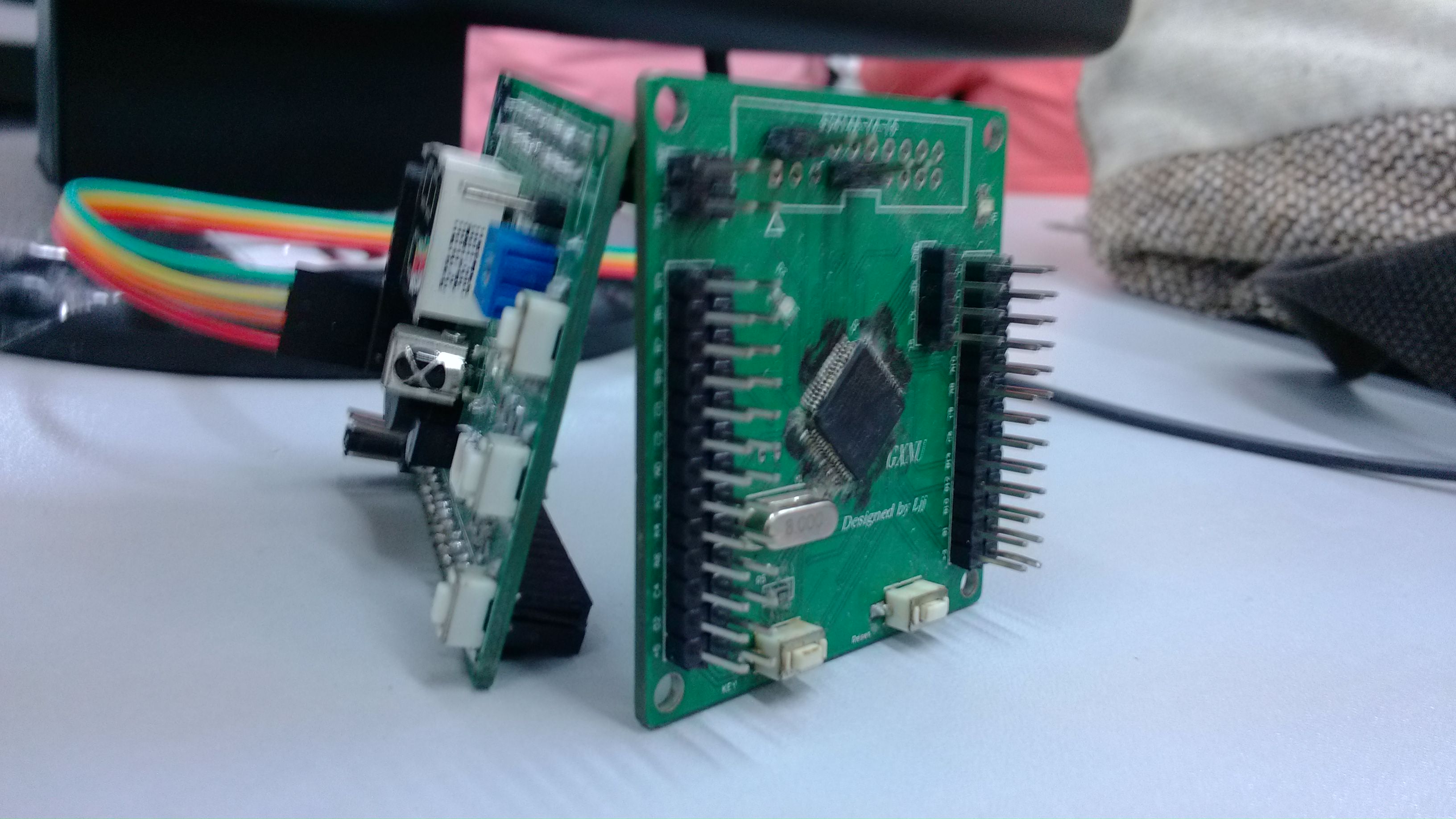
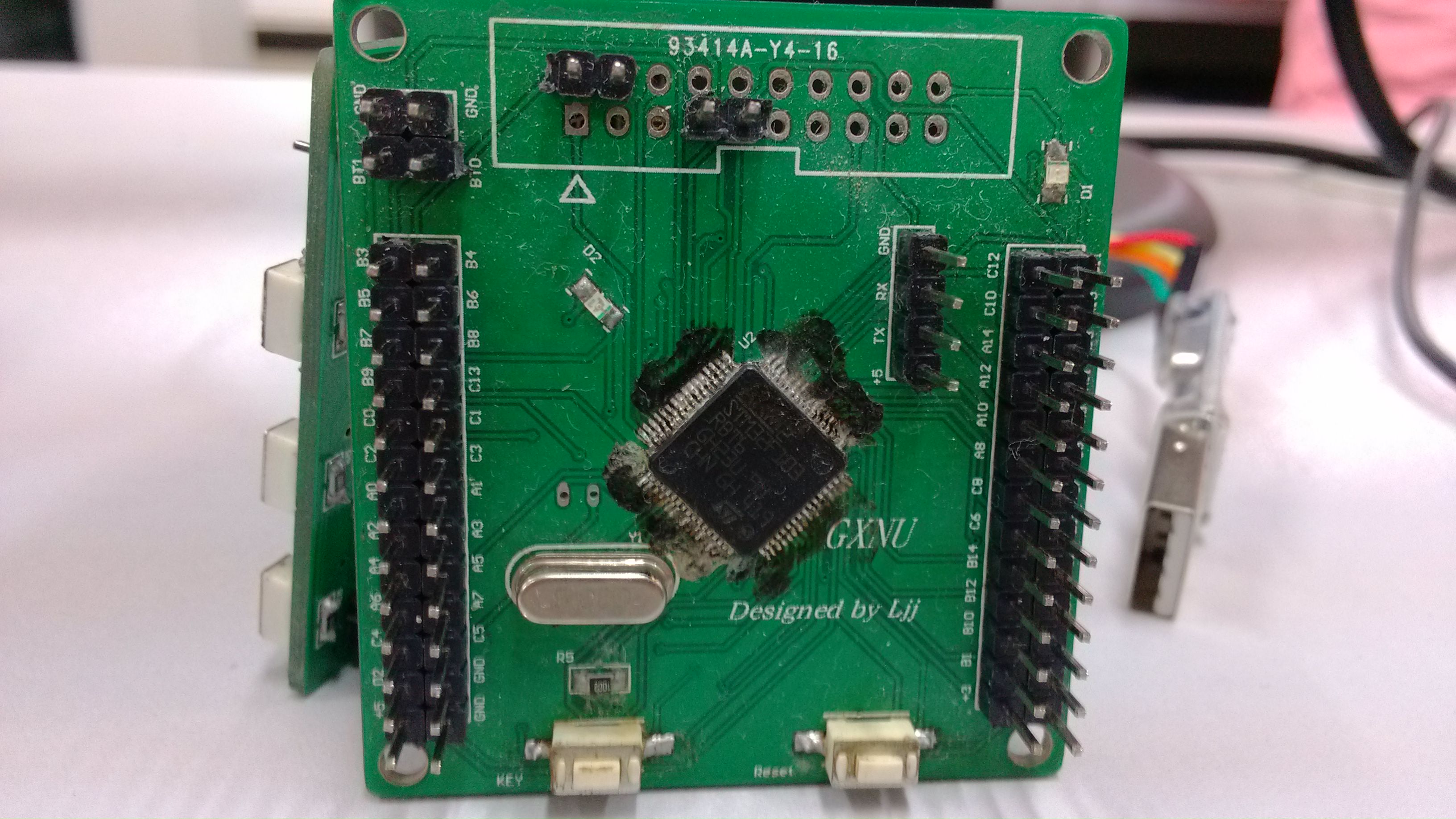
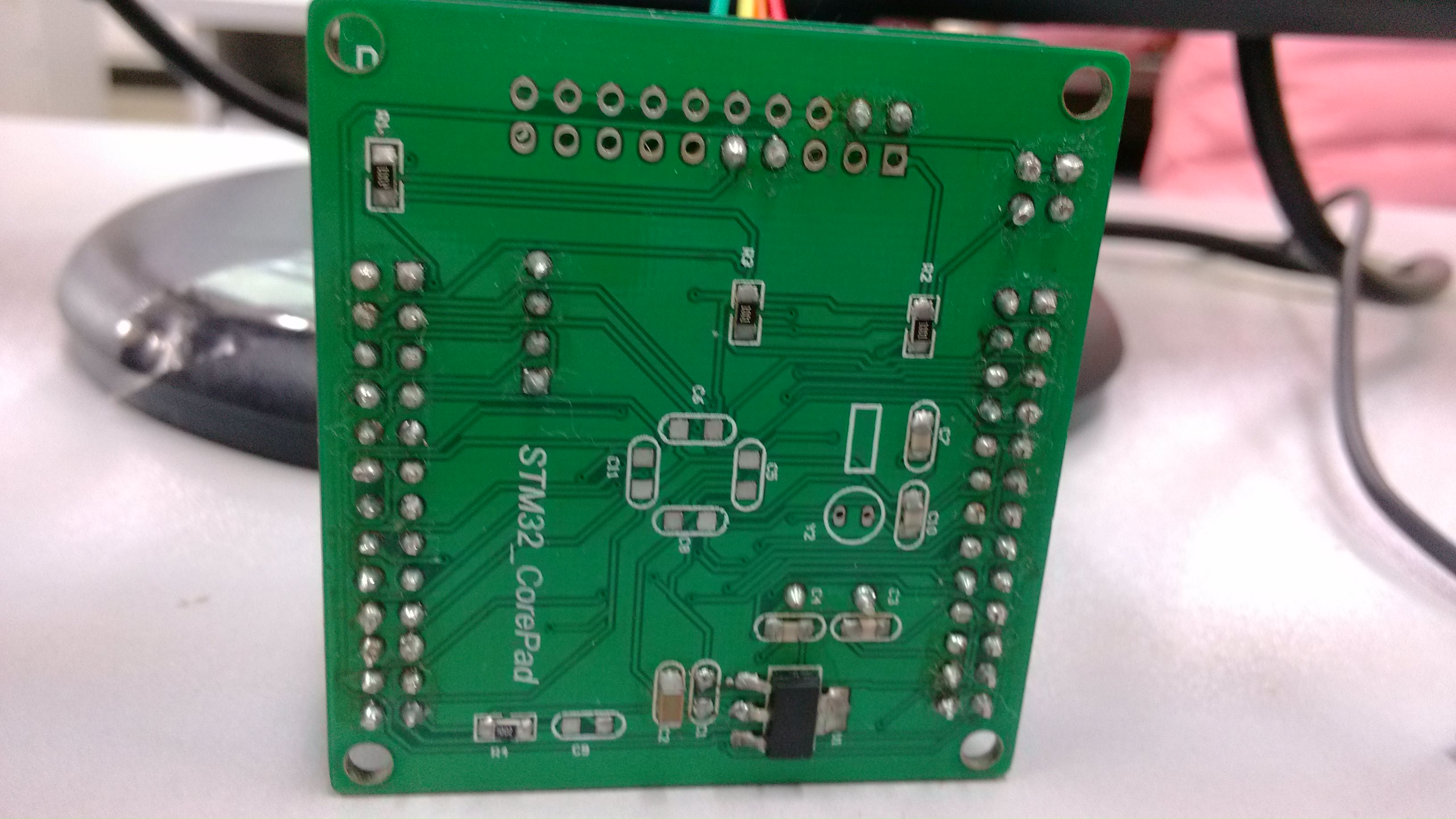
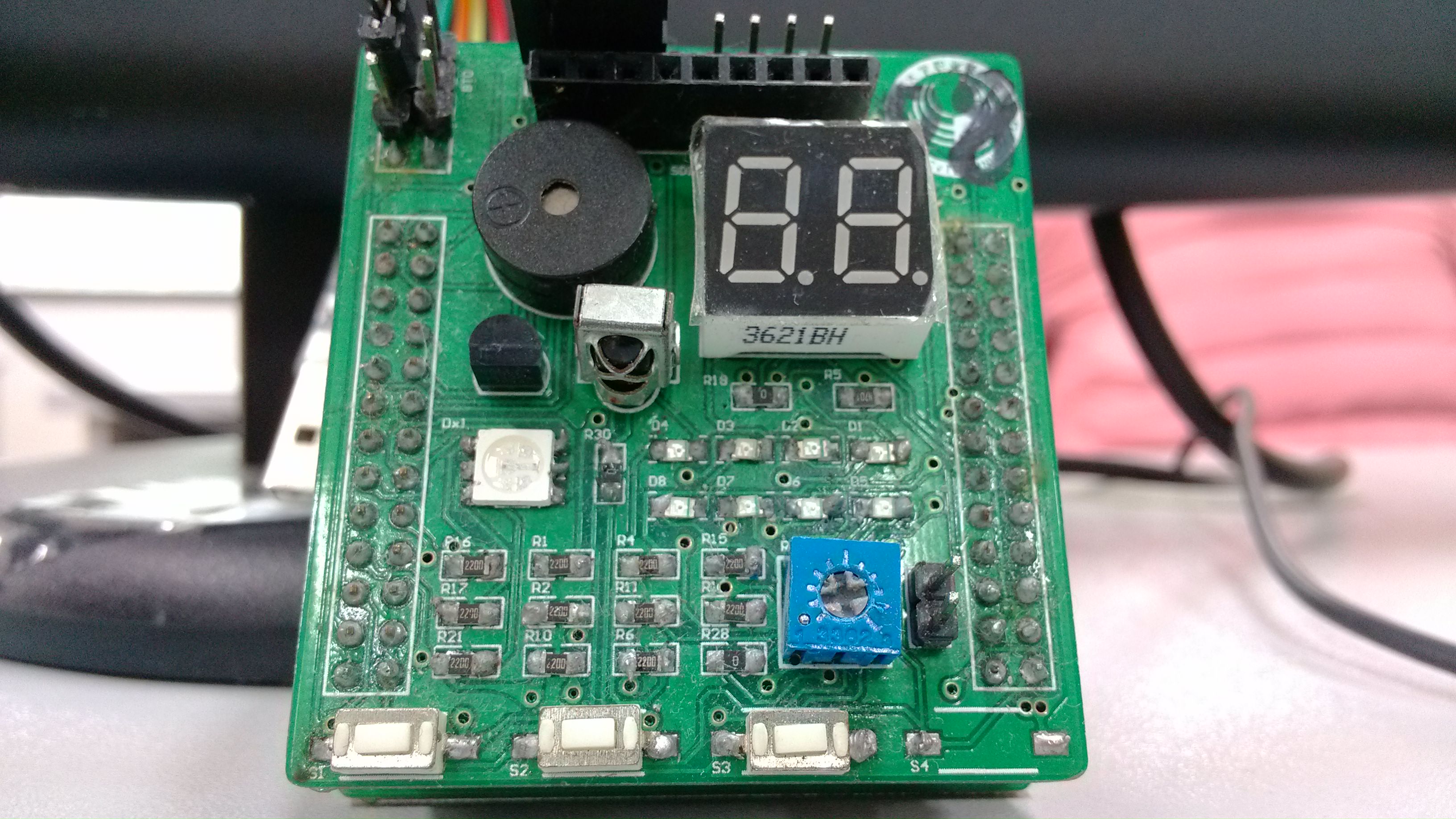
焊板图片:
用ADC写满一页,全部输出:
#include <stm32f10x.h>
#include "stm32_eval.h"
#include <stdio.h>
#include "spi_flash.h"
#define VREF 3.3
#define TxBufferSize1   (countof(TxBuffer1) - 1)
#define RxBufferSize1   (countof(TxBuffer1) - 1)
#define countof(a)      (sizeof(a) / sizeof(*(a)))
#define  BufferSize (countof(Tx_Buffer)-1)
typedef enum { FAILED = 0, PASSED = !FAILED} TestStatus;
#define  FLASH_WriteAddress     0x00000
#define  FLASH_ReadAddress      FLASH_WriteAddress
#define  FLASH_SectorToErase    FLASH_WriteAddress
#define  sFLASH_ID              0xEF3015     //W25X16
//#define  sFLASH_ID              0xEF4015   //W25Q16
#define buff_size  16;
char rx_buff_count=0;

uint8_t Tx_Buffer[4096] ;  //????
uint8_t Rx_Buffer[BufferSize];  //????
__IO uint32_t DeviceID = 0;  //??ID
__IO uint32_t FlashID = 0; //??ID
__IO TestStatus TransferStatus1 = FAILED;  //????


/**************????*******************/
void delay_us(u32 n)
{
    u8 j;
    while(n--)
    for(j=0;j<10;j++);
}
void  delay_ms(u32 n)
{
    while(n--)
    delay_us(1000);
}

void Delay(__IO uint32_t nCount);
TestStatus Buffercmp(uint8_t* pBuffer1, uint8_t* pBuffer2, uint16_t BufferLength);
GPIO_InitTypeDef   GPIO_InitStructure;
USART_InitTypeDef USART_InitStructure;
USART_ClockInitTypeDef USART_ClockInitStructure;

char *int_to_string(int number,char *strnum)//??????????
{
int j=0,i=0,n=0;
char temp;
while(number>0)
{
*(strnum+j)=number%10+48;
j++;
number=number/10;
n++;
}


for(i=0;i<n/2;i++)
{
temp=*(strnum+j+i-n);
*(strnum+j+i-n)=*(strnum+j-i-1);
*(strnum+j-i-1)=temp;
}
strnum[n]='\0';
return strnum;
}

void RCC_Configuration(void)
{
  RCC_DeInit();
  RCC_DeInit();//?RCC?????????
  RCC_HSICmd(ENABLE);//????????
  while(RCC_GetFlagStatus(RCC_FLAG_HSIRDY) == RESET);//HSI????reset
  RCC_SYSCLKConfig(RCC_SYSCLKSource_HSI);//??HSI??????
  RCC_HSEConfig(RCC_HSE_OFF);//HSE???
  RCC_LSEConfig(RCC_LSE_OFF);//LSE???
  RCC_PLLConfig(RCC_PLLSource_HSI_Div2,RCC_PLLMul_9); //  72HMz
  RCC_PLLCmd(ENABLE);//??PLL??
  while(RCC_GetFlagStatus(RCC_FLAG_PLLRDY) == RESET);
  RCC_ADCCLKConfig(RCC_PCLK2_Div4);//ADC??=PCLK/4
  RCC_PCLK2Config(RCC_HCLK_Div1);//APB2??=HCLK
  RCC_PCLK1Config(RCC_HCLK_Div2);//APB1??=HCLK/2
  RCC_HCLKConfig(RCC_SYSCLK_Div1);//AHB??=????
  RCC_SYSCLKConfig(RCC_SYSCLKSource_PLLCLK);//??PLL??????
  while(RCC_GetSYSCLKSource() != 0x08);

  RCC_APB2PeriphClockCmd(RCC_APB2Periph_GPIOD|RCC_APB2Periph_AFIO, ENABLE);
  GPIO_PinRemapConfig(GPIO_Remap_SWJ_JTAGDisable,ENABLE);//disable JTAG
  GPIO_InitStructure.GPIO_Pin = GPIO_Pin_2;
  GPIO_InitStructure.GPIO_Speed = GPIO_Speed_50MHz;
  GPIO_InitStructure.GPIO_Mode = GPIO_Mode_Out_PP;
  GPIO_Init(GPIOD, &GPIO_InitStructure);
  GPIO_ResetBits(GPIOD,GPIO_Pin_2);//?????

  RCC_APB2PeriphClockCmd(RCC_APB2Periph_GPIOC|RCC_APB2Periph_AFIO, ENABLE);
  GPIO_PinRemapConfig(GPIO_Remap_SWJ_JTAGDisable,ENABLE);//disable JTAG
  GPIO_InitStructure.GPIO_Pin = GPIO_Pin_0|GPIO_Pin_1|GPIO_Pin_2|GPIO_Pin_3|GPIO_Pin_4|GPIO_Pin_5|GPIO_Pin_6|GPIO_Pin_7;
  GPIO_InitStructure.GPIO_Speed = GPIO_Speed_50MHz;
  GPIO_InitStructure.GPIO_Mode = GPIO_Mode_Out_PP;
  GPIO_Init(GPIOC, &GPIO_InitStructure);
  GPIO_SetBits(GPIOC,GPIO_Pin_0|GPIO_Pin_1|GPIO_Pin_2|GPIO_Pin_3|GPIO_Pin_4|GPIO_Pin_5|GPIO_Pin_6|GPIO_Pin_7);
  RCC_APB1PeriphClockCmd(RCC_APB1Periph_TIM2, ENABLE);
}

void USART_int(long BaudRate)
{
    RCC_APB2PeriphClockCmd(RCC_APB2Periph_GPIOA|RCC_APB2Periph_USART1,ENABLE);
    GPIO_InitStructure.GPIO_Pin = GPIO_Pin_9;
    GPIO_InitStructure.GPIO_Speed = GPIO_Speed_50MHz;
    GPIO_InitStructure.GPIO_Mode = GPIO_Mode_AF_PP;
    GPIO_Init(GPIOA, &GPIO_InitStructure);
    /* PA10 USART1_Rx  */
    GPIO_InitStructure.GPIO_Pin = GPIO_Pin_10;
    GPIO_InitStructure.GPIO_Mode = GPIO_Mode_IN_FLOATING;
    GPIO_Init(GPIOA, &GPIO_InitStructure);
    /* USARTx configured as follow:
        - BaudRate = 115200 baud
        - Word Length = 8 Bits
        - One Stop Bit
        - No parity
        - Hardware flow control disabled (RTS and CTS signals)
        - Receive and transmit enabled
    */
  USART_InitStructure.USART_BaudRate = BaudRate;
  USART_InitStructure.USART_BaudRate = BaudRate;//usart?????
  USART_InitStructure.USART_WordLength = USART_WordLength_8b;//???????8bit
  USART_InitStructure.USART_StopBits = USART_StopBits_1;//??????1????
  USART_InitStructure.USART_Parity = USART_Parity_No;//????
  USART_InitStructure.USART_HardwareFlowControl = USART_HardwareFlowControl_None;//???????
  USART_InitStructure.USART_Mode = USART_Mode_Rx | USART_Mode_Tx;//????,????
  USART_ClockInitStructure.USART_Clock = USART_Clock_Disable;//???????
  USART_ClockInitStructure.USART_CPOL = USART_CPOL_Low;//?????
  USART_ClockInitStructure.USART_CPHA = USART_CPHA_2Edge;//????????????
  USART_ClockInitStructure.USART_LastBit = USART_LastBit_Disable;//???????????SCLK??
  USART_ClockInit(USART1, &USART_ClockInitStructure);//??USART1??
  USART_Init(USART1, &USART_InitStructure);//???USART1
  USART_Cmd(USART1, ENABLE);//??USART1??
  USART_ITConfig(USART1, USART_IT_RXNE, ENABLE);//????
  USART_Cmd(USART1, ENABLE);
}

TestStatus Buffercmp(uint8_t* pBuffer1, uint8_t* pBuffer2, uint16_t BufferLength)
{
  while(BufferLength--)
  {
    if(*pBuffer1 != *pBuffer2)
    {
      return FAILED;
    }

    pBuffer1++;
    pBuffer2++;
  }
  return PASSED;
}

void Delay(__IO uint32_t nCount)
{
  for(; nCount != 0; nCount--);
}

void ADC_CONFIG(){
    ADC_InitTypeDef ADC_InitStructure;
    #if defined (STM32F10X_LD_VL) || defined (STM32F10X_MD_VL) || defined (STM32F10X_HD_VL)
  /* ADCCLK = PCLK2/2 */
  RCC_ADCCLKConfig(RCC_PCLK2_Div2);
#else
  /* ADCCLK = PCLK2/4 */
  RCC_ADCCLKConfig(RCC_PCLK2_Div4);
#endif
ADC_DeInit(ADC1);
  /* Enable ADC1 and GPIOC clock */
  RCC_APB2PeriphClockCmd(RCC_APB2Periph_ADC1 | RCC_APB2Periph_GPIOB, ENABLE);

    /* Configure PB0 (ADC Channel14) as analog input -------------------------*/
  GPIO_InitStructure.GPIO_Pin = GPIO_Pin_0;
  GPIO_InitStructure.GPIO_Mode = GPIO_Mode_AIN;
  GPIO_Init(GPIOB, &GPIO_InitStructure);


  /* ADC1 configuration ------------------------------------------------------*/
  ADC_InitStructure.ADC_Mode = ADC_Mode_Independent;
  ADC_InitStructure.ADC_ScanConvMode = ENABLE;
  ADC_InitStructure.ADC_ContinuousConvMode = ENABLE;
  ADC_InitStructure.ADC_ExternalTrigConv = ADC_ExternalTrigConv_None;
  ADC_InitStructure.ADC_DataAlign = ADC_DataAlign_Right;
  ADC_InitStructure.ADC_NbrOfChannel = 1;
  ADC_Init(ADC1, &ADC_InitStructure);


  /* Enable ADC1 DMA */
  ADC_DMACmd(ADC1, ENABLE);

  /* Enable ADC1 */
  ADC_Cmd(ADC1, ENABLE);

}

int Get_ADC(){
     /* ADC1 regular channel configuration */
  ADC_RegularChannelConfig(ADC1, ADC_Channel_8, 1, ADC_SampleTime_55Cycles5);
    /* Enable ADC1 reset calibration register */
  ADC_ResetCalibration(ADC1);
  /* Check the end of ADC1 reset calibration register */
  while(ADC_GetResetCalibrationStatus(ADC1));

  /* Start ADC1 calibration */
  ADC_StartCalibration(ADC1);
  /* Check the end of ADC1 calibration */
  while(ADC_GetCalibrationStatus(ADC1));

  /* Start ADC1 Software Conversion */
  ADC_SoftwareStartConvCmd(ADC1, ENABLE);

    return ADC_GetConversionValue(ADC1);
}


void SPI_TEST()
{
    int i=0;
    int ADValue = 0;
    float Volt=0.00;
//    char shuzu[100];
    for(i=0;i<5;i++){
      ADValue = Get_ADC();
      Volt = VREF*ADValue/4095;
      printf("===============================\r\n");
      printf("The ADC value is:%d\r\n",ADValue);
      printf("The Volt is:%f V\r\n",Volt);
      delay_ms(500);
}

    printf("\r\n????2M SPI??flash(W25X16)?? \r\n");
    SPI_FLASH_Init();
    /* Get SPI Flash Device ID */
    DeviceID = SPI_FLASH_ReadDeviceID();
    Delay( 200 );
    /* Get SPI Flash ID */
    FlashID = SPI_FLASH_ReadID();
    printf("\r\n FlashID is 0x%X,  Manufacturer Device ID is 0x%X\r\n", FlashID, DeviceID);
    /* Check the SPI Flash ID */
    if (FlashID == sFLASH_ID)  /* #define  sFLASH_ID  0xEF3015 */
    {
        printf("\r\n ?????flash W25X16 !\r\n");
        /* Erase SPI FLASH Sector to write on */
        SPI_FLASH_SectorErase(FLASH_SectorToErase);

        /*??????*/
        SPI_FLASH_BufferWrite(Tx_Buffer, FLASH_WriteAddress, BufferSize);
        printf("\r\n??????:%s \r\t", Tx_Buffer);

        /* ?????????*/
        SPI_FLASH_BufferRead(Rx_Buffer, FLASH_ReadAddress, BufferSize);
        printf("\r\n??????:%s \r\n", Rx_Buffer);

        TransferStatus1 = Buffercmp(Tx_Buffer, Rx_Buffer, BufferSize);

        if( PASSED == TransferStatus1 )
        {
            printf("\r\n 2M SPI??flash(W25X16)????!\n\r");
        }
        else
        {
            printf("\r\n 2M SPI??flash(W25X16)????!\n\r");
        }
    }// if (FlashID == sFLASH_ID)
    else
    {
        printf("\r\n ???? W25X16 ID!\n\r");
    }

    SPI_Flash_PowerDown();
    printf("\r\n=================================================\n\r");
}

int main(void)
{
  RCC_Configuration();
  USART_int(115200);
  ADC_CONFIG();
  printf(" config done...\r\n");
  Get_ADC();
  delay_ms(1000);
  while(1){
    SPI_TEST();
    delay_ms(1000);
}
}

#ifdef  USE_FULL_ASSERT

void assert_failed(uint8_t* file, uint32_t line)
{
  while (1)
  {
  }
}

#endif
#ifdef __GNUC__
  /* With GCC/RAISONANCE, small printf (option LD Linker->Libraries->Small printf
     set to 'Yes') calls __io_putchar() */
  #define PUTCHAR_PROTOTYPE int __io_putchar(int ch)
#else
  #define PUTCHAR_PROTOTYPE int fputc(int ch, FILE *f)
#endif /* __GNUC__ */

PUTCHAR_PROTOTYPE
{
  /* Place your implementation of fputc here */
  /* e.g. write a character to the USART */
  USART_SendData(EVAL_COM1, (uint8_t) ch);
  /* Loop until the end of transmission */
  while (USART_GetFlagStatus(EVAL_COM1, USART_FLAG_TC) == RESET)
  {}

  return ch;
}

#ifdef  USE_FULL_ASSERT

void assert_failed(uint8_t* file, uint32_t line)
{
  while (1)
  {
  }
}

#endif
 我要赚赏金打赏帖 我要赚赏金打赏帖 |
|
|---|---|
| STM32C0116DK开发探索记(3)被打赏¥30元 | |
| STM32C0116DK开发探索记(2)被打赏¥24元 | |
| STM32C0116DK开发探索记(1)被打赏¥29元 | |
| 谨防极海G32M3101电机评估板易跌落的陷阱被打赏¥24元 | |
| 【全网首拆】M5STACK ATOM系列开发板拆解 / AtomS3R-CAM摄像头更换方法(提高10倍像素)被打赏¥26元 | |
| 基于MCP23S17的输入输出功能模块控制被打赏¥20元 | |
| 【S32K3XX】SPD 软件包使用Link文件修改被打赏¥22元 | |
| Switch-Case局部变量定义问题被打赏¥23元 | |
| 基于米尔TIAM62L开发板的串口通信及应用被打赏¥20元 | |
| PCF8574功能模块及其使用被打赏¥20元 | |
 STM32
STM32 MCU
MCU 通讯及无线技术
 物联网技术
物联网技术 电子DIY
电子DIY 板卡试用
板卡试用 基础知识
基础知识 软件与操作系统
 我爱生活
我爱生活 小e食堂
小e食堂

