道路车道检测系统:
自动驾驶汽车是现代世界的新趋势之一。他们使用非常复杂的控制系统和工程技术来操纵车辆。道路车道检测是车辆导航中的重要内容之一。在这里,我描述了一个使用 Raspberry pi 3 和计算机视觉技术的简单快速的车道检测。为了快速计算,我只是避免使用线性回归方法。这种方法在低噪声环境下效果很好,但对于复杂的场景,需要先进的统计和图像处理技术。
硬件设置:
将相机与您的 Pi 连接
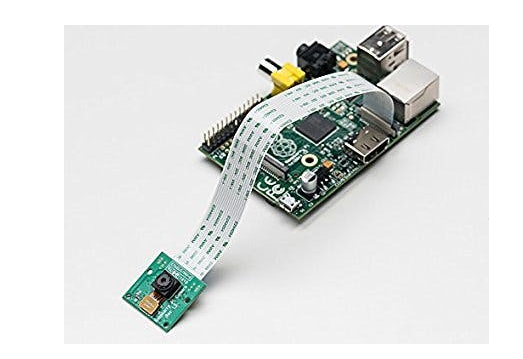
摄像头配置:
按照此链接进行相机设置https://www.raspberrypi.org/documentation/configuration/camera.md
软件设置:
为 python 安装 OpenCV。按照这些说明安装 OpenCV。这些说明是从https://raspberrypi.stackexchange.com复制的。
通用:
sudo apt-get update
sudo apt-get upgrade
sudo rpi-update
sudo reboot
sudo apt-get install build-essential git cmake pkg-config
sudo apt-get install libjpeg-dev libtiff5-dev libjasper-dev libpng12-dev
sudo apt-get install libavcodec-dev libavformat-dev libswscale-dev libv4l-dev
sudo apt-get install libxvidcore-dev libx264-dev
sudo apt-get install libgtk2.0-dev
sudo apt-get install libatlas-base-dev gfortran
cd ~
git clone
cd opencv
git checkout 3.1.0
cd ~
git clone
cd opencv_contrib
git checkout 3.1.0
如果您想将 OpenCV 与 python 2.7 一起使用:
sudo apt-get install python2.7-dev
wget
sudo python
pip install numpy
cd ~/opencv
mkdir build
cd build
cmake -D CMAKE_BUILD_TYPE=RELEASE \
-D INSTALL_C_EXAMPLES=OFF \
-D INSTALL_PYTHON_EXAMPLES=ON \
-D OPENCV_EXTRA_MODULES_PATH=~/opencv_contrib/modules \
-D BUILD_EXAMPLES=ON ..
make -j4
sudo make install
sudo ldconfig
如果您想在 Python 3 中使用 OpenCV:
sudo apt-get install python3-dev
wget
sudo python3
pip install numpy
cd ~/opencv
mkdir build
cd build
cmake -D CMAKE_BUILD_TYPE=RELEASE \
-D CMAKE_INSTALL_PREFIX=/usr/local \
-D INSTALL_C_EXAMPLES=OFF \
-D INSTALL_PYTHON_EXAMPLES=ON \
-D OPENCV_EXTRA_MODULES_PATH=~/opencv_contrib/modules \
-D BUILD_EXAMPLES=ON ..
make -j4
sudo make install
sudo ldconfig
将以上配置完成大约需要 2 个小时。在此期间,我们可以了解一下 Hough-Transform,这项技术是大多数实用车道检测算法背后的关键。
Python代码:
from picamera.array import PiRGBArray
import RPi.GPIO as GPIO
from picamera import PiCamera
import time
import cv2
import numpy as np
import math
GPIO.setmode(GPIO.BOARD)
GPIO.setup(7, GPIO.OUT)
GPIO.setup(8, GPIO.OUT)
theta=0
minLineLength = 5
maxLineGap = 10
camera = PiCamera()
camera.resolution = (640, 480)
camera.framerate = 30
rawCapture = PiRGBArray(camera, size=(640, 480))
time.sleep(0.1)
for frame in camera.capture_continuous(rawCapture, format="bgr", use_video_port=True):
image = frame.array
gray = cv2.cvtColor(image, cv2.COLOR_BGR2GRAY)
blurred = cv2.GaussianBlur(gray, (5, 5), 0)
edged = cv2.Canny(blurred, 85, 85)
lines = cv2.HoughLinesP(edged,1,np.pi/180,10,minLineLength,maxLineGap)
if(lines !=None):
for x in range(0, len(lines)):
for x1,y1,x2,y2 in lines[x]:
cv2.line(image,(x1,y1),(x2,y2),(0,255,0),2)
theta=theta+math.atan2((y2-y1),(x2-x1))
#print(theta)GPIO pins were connected to arduino for servo steering control
threshold=6
if(theta>threshold):
GPIO.output(7,True)
GPIO.output(8,False)
print("left")
if(theta<-threshold):
GPIO.output(8,True)
GPIO.output(7,False)
print("right")
if(abs(theta) GPIO.output(8,False)
GPIO.output(7,False)
print "straight"
theta=0
cv2.imshow("Frame",image)
key = cv2.waitKey(1) & 0xFF
rawCapture.truncate(0)
if key == ord("q"):
break):
示例输出结果:
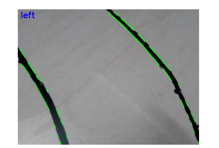
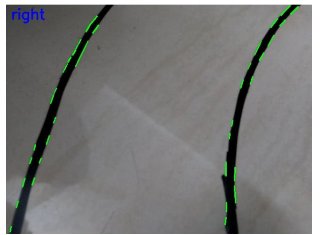
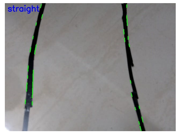
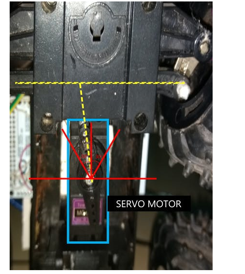
GPIO 引脚连接到 Arduino mega 用于伺服电机控制。
#include
Servo myservo;
void setup() {
myservo.attach(10);//attach servo motor PWM(orange) wire to pin 10
pinMode(0, INPUT);//attach GPIO 7&8 pins to arduino pin 0&1
pinMode(1,INPUT);
void loop() {
if(digitalRead(0)==HIGH && digitalRead(1)==LOW)
{
myservo.write(118);
}
if(digitalRead(1)==HIGH && digitalRead(0)==LOW)
{
myservo.write(62);
}
if(digitalRead(1)==LOW && digitalRead(0)==LOW)
{
myservo.write(90);
}
}

 我要赚赏金
我要赚赏金

