
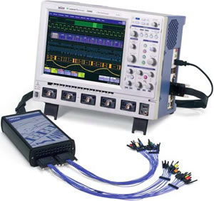
CANbus TD or TDM combines standard LeCroy oscilloscope capabilities, CAN Bus triggering, and protocol decode in one test system. Now it’s simple to capture a specific CAN message or error frame and view protocol data on the same display as the CAN signal or analog signals. Understanding system problems and performance has never been this easy! LeCroy CANbus TD or TDM, and a LeCroy WaveRunner, WaveSurfer or WavePro 7 Zi Series oscilloscope, is the solution for locating CAN Bus anomalies and debugging CAN Bus controllers and systems.
- Comprehensive CAN trigger, decode and protocol measurements in a single instrument
- Flexible CAN trigger includes:
- CAN Data
- Remote Frames
- Error Frames
- Powerful Conditional Frame ID and Data triggering (>, >=, <, <=, <>, In Range, Out of Range)
- Easily view the decoded signals with an intuitive color-coded decode overlay
- Measure performance and statistically analyze
- Graph and plot performance data
- Supports CAN signals with bit rates from 10 kb/s to 1 Mb/s
- Convenient table display with "zoom to byte" capability
- Quick search capability for specific
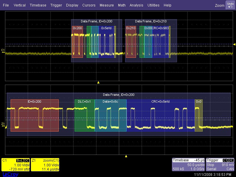
Trigger on CAN Frame Ids and Data, apply a color-coded, easy to understand decode over your CAN signal, perform bus timing measurements and extract data from the CAN message.
The CAN trigger, decode and measurement package is the solution for locating CAN Bus anomalies and debugging CAN Bus controllers and systems. It is unique in allowing correlation of physical layer signals with protocol layer data information. Having all of your information in one instrument will allow you to intuitively find problems that you weren't aware of, increase parts and systems reliability, save time and lower costs.
Built-in Oscilloscope TriggerMakes Setup EasyIsolate specific CAN messages with the built-in oscilloscope trigger. All the triggering is done in the oscilloscope and setup is completely integrated into LeCroy's intuitive trigger menu.
The Most Intuitive DecodePatented software algorithms deconstruct the waveform into protocol decode information, then overlay the decoded data on the waveform. Depending on the timebase setting or the amount of zoom, the decode information is condensed or expanded to better assist in understanding events during short or long acquisitions. Various sections of the protocol such as ID, DLC, CRC, Data and Errors are color-coded to make it easy to understand. The decode operation is fast—even with long acquisitions.
Measure and Plot PerformancePowerful measurements and sophisticated statistical, graphical, and plotting tools simplify CAN Bus debugging. Understanding CAN Bus system problems and performance is quick and easy.
Extensive TriggeringThe flexible CAN Bus trigger allows trigger setup in multiple formats for a wide variety of setup conditions and is completely integrated inside the oscilloscope. The trigger will quickly locate and isolate specific Frame Ids, Remote Frames or Error Frames eliminating the need to search through a long capture for the right CAN message. Conditional triggering provides the ability to trigger on a range of Frame Ids or data messages.
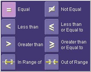
Trigger on a single CAN ID and data message or a range of values using the powerful conditional trigger capabilities.
Timing and Bus MeasurementsCAN specific measurement parameters allow you to quickly and easily characterize your CAN system and make gateway measurements. Use the CAN-CAN parameter to find the time between two essages on the bus or the CAN-Analog parameter to correlate CAN bus traffic to an analog signal. Use LeCroy's measurement statistics and histicons to understand the range of measurements on the CAN bus.
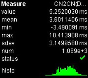
Quickly make CAN timing measurements and monitor system performance with the CANbus TDM parameters. LeCroy's statistical measurements with histograms, tracks and trends let you see how the bus behaves over time.
Data Extraction and GraphingExtract data from the CAN message stream and use the track functions to graphically plot that data on the oscilloscope display. The digital data is used to create an analog waveform that can then be compared to other electrical signals.
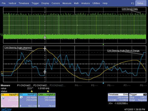
Here, information on the steering angle and steering angle rate of change is extracted from the CAN message acquisition, rescaled to decimal values, and plotted as a time-correlated “Track” on the VBA display.
Convenient Table Display Summarizes ResultsTurn your oscilloscope into a protocol analyzer with the Table display of decoded information. Custom configure the Table to display only the information you want and export Table data to an Excel file. Touch a message in the table and automatically zoom for detail.

Display your values in an easy-to-understand table. Touch a row to zoom, or export to Excel with one button push.
Search and ZoomID or Data values can be quickly located by searching for a specific value. In a long acquisition, pressing NEXT advances the single byte to the byte right or left of the current message.
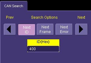
Search through long record of decoded data by entering the message or address you are looking for and clicking the right or left search arrows.
More Tools for YourEmbedded System TestLeCroy offers the same powerful triggering and intuitive decoding capabilities for LIN, FlexRay, I2C, SPI, and UART signals. For complete embedded system testing the MS Series mixed signal oscilloscopes add 18 or 36 digital channels to the scilloscope allowing you to look at all your analog, digital, and serial data waveforms simultaneously with complete analog/digital cross pattern triggering.
LeCroy’s MS Series high-performance mixed signal option provides a maximum input frequency of up to 500 MHz and up to 50 Mpts of memory per channel.
CompatibilityWPZi-CANbus TDM and WRXi-CANbus TDM are compatible with the WavePro? Zi and WaveRunner? Xi oscilloscopes. WPZi-CANbus TD, WRXi-CANbus TD and WSXs-CANbus TD are compatible with WavePro Zi, WaveRunner Xi and WaveSurfer? Xs oscilloscopes. The minimum required software version is 5.7.2.1.
CAN trigger, decode and measure/graph functionality is available on other LeCroy X-Stream oscilloscopes through use of an external trigger module. The following is a description of what is included with the external CAN trigger module.
- Trigger Module with TC251-OPTO optically isolated Trigger Coupler installed (and room for one additional Trigger Coupler). Trigger Couplers are interchangeable.
- LeCroy CANbus TD Series Oscilloscope Interface Module with 1.0 meter connection cable. Connects Trigger Module to LeCroy oscilloscope ProBus? Interface.
- Software for:
- Trigger Setup
- CAN Protocol Decode
- CAN Measurement, (CAN-analog, CAN-CAN, and Time@CAN timing parameters, CAN bus load% and CAN-Value Data Extraction parameters)
- Histogramming
- Graphing (Track and Trend)
- 1.0 meter USB 2.0 cable from LeCroy external CANbus TD Trigger Module to LeCroy oscilloscope
- Black fabric storage case (SAC-01) with foam insert and room for storage of all equipment and two additional Trigger Coupler accessories (not included)
- Quantity 1 (one) 9-pin DSUB socket to 2-wire adapter cable (for ISO 11898-2 CAN)
- Quantity 1 (one) 9-pin DSUB socket to 4-wire adapter cable (dual-use, for ISO 11519 CAN and GM-LAN/J2411 CAN)
- Quantity 2 (two) 9-pin to 9-pin DSUB 120 ohm terminations
- Quick Reference Guide in English
- Instruction Manual in English
- Quantity 1 (one) Phillips head screwdriver and work with an external trigger module not shown in this datasheet.
 STM32
STM32 MCU
MCU 通讯及无线技术
 物联网技术
物联网技术 电子DIY
电子DIY 板卡试用
板卡试用 基础知识
基础知识 软件与操作系统
 我爱生活
我爱生活 小e食堂
小e食堂