|
Leading Features
- I2C, SPI, UART and RS-232 Trigger and Decode
- Color-coded decode overlaid on the waveform is intuitive and easy to read
- Powerful and flexible conditional DATA triggering (=, <, <=, >, >=, <>, in range, out ofrange)
- Hex, Binary or ASCII decoding
- Decode information expands as the timebase is adjusted or zoomed
- Convenient table display with quick "zoom to message" capability
- Quick search capability for specific messages
- Set an ACK condition (ACK,NO ACK, Don’t Care) in all frame trigger setups (I2C)
- Decode does not require clock trace to be displayed (I2C, SPI)
- Supports UART address (9-bit) Byte triggering
- Supports trigger and decode of user defined proprietary protocols based on a UART backbone
The Most Intuitive Decode
Advanced software algorithms decon struct the waveform into protocol information, then overlay the decoded data on the waveform. Decode information condenses or expands depending on the timebase/zoom ratio setting, so understanding messages is easy. Various sections of the protocol are color-coded to make it easy to understand, especially for users new to I2C, SPI, UART, and RS-232 serial data. The decode operation is fast—even with long acquisitions. The user can choose to decode into Hex, Binary, or ASCII formats.
LeCroy’s decode algorithms allow the CLOCK signal to be input to the external channel, which saves valuable channels for other signals. Or, if the CLOCK signal is input to a channel, it can be turned OFF as desired to reduce display clutter.
Powerful Conditional Data Triggering
Completely isolate specific I2C, SPI, UART, or RS-232 message events for better understanding and debug. Use a conditional DATA trigger to select a range of DATA values to trigger on, not just a single DATA value. Oftentimes, I2C utilizes DATA bytes to specify sub-addresses for accessing memory locations in EEPROMs. Condi tional DATA trigger allows triggering on a range of DATA bytes that correspond to reads or writes to specific sub-address memory blocks in the EEPROM. It can also aid in monitoring DATA outputs from I2C-based sensors, such as analog-todigital con verters, and triggering when DATA is outside a safe operating range. In both cases, verifying proper operation becomes a simple task. Of course, all the basic I2C and SPI triggering capability you would expect is also included.
Full UART and RS-232 Capability and Customization
Complete support for any configuration of UART and standard RS-232. Generic UART is commonly used as the backbone for proprietary protocols, and the flexible setup configuration allows definition to meet your exact need.
Flexible Triggering
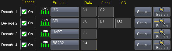
Simultaneously decode up to 4 serial data buses. When using the MSO option on WaveRunner Xi or WaveSurfer Xs the digital inputs D0, D1, D2, etc. can be used as the source for a serial data trigger and decode.
I2C, SPI, and UART all have special use cases and the LeCroy Trigger and Decode solutions address these cases. The I2C trigger can be configured for 7 or 10-bit addressing with out without inclusion of the R/W bit. The SPI trigger can be configured for a range of CPOL and CPHA settings as well as the Simplified SPI protocol. With the UART trigger 8 and 9-bit (8+1) formats are supported.
Convenient Table Display Summarizes Results
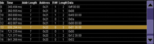
Display your values in an easy-to-understand table. Touch a row to zoom, or export to Excel with one button push.
Turn your oscilloscope into a protocol analyzer with the Table display of protocol information. Custom configure the Table to display only the infor mation you want, and export Table data to an Excel file. Touch a message in the table and auto matically zoom for detail. In all cases, the Table never obscures your waveform data.
Search and Zoom
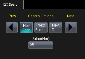
Search through long record of decoded data by entering the message or address you are looking for and clicking the right or left search arrows.
I2C, SPI, UART, and RS-232 messages can be quickly located by search ing on Address (I2C) or DATA (I2C, SPI, UART, RS-232). Pressing an arrow button advances the single zoomed message view one message to the right or left of the current message.
| |
I2Cbus TD |
SPIbus TD |
UART-RS232bus TD |
| |
Definition |
|
|
| Protocol Setup |
N.A. |
Select CPOL, CPHA, DATA = MSB or LSB. Also, may select SIOP, SSPI or DDR (Double Data Rate) Defaults. |
For UART
Select BitRate
Select # Data Bits (5-9)
Select Parity (Odd, Even, None)
Select # Stop Bits (1, 1.5, 2)
Select Bit Order (MSB or LSB)
Select Polarity (IdleLow or IdleHigh)
For RS-232
Select BitRate
Select # Data Bits (5-8)
Select Parity (Odd, Even, None)
Select # Stop Bits (1, 1.5, 2) |
| |
Decode Capability |
|
|
| Format |
Hexadecimal, Binary, ASCII |
Hexadecimal, Binary, ASCII |
Hexadecimal, Binary, ASCII |
| Decode Setup |
Threshold definition required. Default is to Percent amplitude. Choose to Decode address values including/not including the R/W bit in address value. |
Threshold definition required.
Default is to Percent amplitude.
Select CPOL, CPHA, DATA = MSB or LSB. |
Threshold definition required. Default is to Percent amplitude. Select BitRate, # Data Bits, Parity, # Stop Bits, Bit Order, and Polarity (for RS-232, no Bit Order or Polarity setup). |
| Decode Input |
Any analog Channel, Memory, or Math trace. |
Any analog Channel, Memory, or Math trace. |
Any analog Channel, Memory, or Math trace. |
| # of Decoded Waveforms |
Up to 4 buses may be decoded at one time.
Sources can be Channels or Memory Waveforms.
In addition, zooms can be displayed
(with decoded information). |
Up to 4 buses may be decoded at one time.
Sources can be Channels or Memory Waveforms.
In addition, zooms can be displayed
(with decoded information). |
Up to 4 buses may be decoded at one time.
Sources can be Channels or Memory Waveforms.
In addition, zooms can be displayed
(with decoded information). |
| Location |
Overlaid over DATA waveform, on Grid |
Overlaid over DATA waveform, on Grid |
Overlaid over DATA waveform, on Grid. |
| Visual Aid |
Color Coding for FRAME, START/ReSTART bit, ADDR, R/W, DATA, ACK, and STOP bit |
Color Coding for FRAME and DATA |
Color Coding for Start Bit, Stop Bit, Parity Bit, and DATA. Decode information is intelligently annotated based on timebase setting. |
| |
Trigger Capability |
|
|
| Format |
Hexadecimal or Binary. ADDRESS and DATA can be set up with different formats. |
Hexadecimal or Binary. |
Hexadecimal or Binary |
| Trigger Setup |
Trigger on START, ReSTART, STOP, ADDR, DATA,
ADDR+DATA, Data Length, Missing ACK |
Trigger on DATA |
Trigger on DATA or Parity ERROR |
| ADDRESS Condition Setup |
Specify one ADDRESS with condition of = 7 or 10 bit ADDRESS supported with full Read, Write, or R/W=”Don’t Care” selectability on both 7 and
10 bit ADDRESSes
Choose to Trigger on address values that include/don’t include R/W bit in address value. |
N.A. |
N.A. |
| DATA Condition Setup |
<=, <, =, >, >=, <>, in range, out of range, don’t care. |
<=, <, =, >, >=, <>, in range, out of range, don’t care. |
<=, <, =, >, >=, <>, in range, out of range, don’t care. |
| DATA Setup |
Hexadecimal: # Data Bytes = 0 to 12. Data can be defined by nibble.
Binary: Any combination of 0,1, or X for 1-96 bits.
Data pattern can be set to start on any byte in a 2048-byte window (EEPROM mode only). |
Hexadecimal: # Data Bytes = 0 to 12. Data can be defined by nibble. Binary: Any combination of 0,1, or X for 1-96 bits.
Triggers on that data pattern in a specified location. |
Hexadecimal: # Data Bytes = 0 to 12. Data can be defined by nibble. Binary: Any combination of 0,1, or X for 1-96 bits.
May specify particular data position anywhere in a 2048 byte sequence. |
| ACK Condition Setup |
For any ADDR, ADDR+DATA, ADDR+DATA LENGTH, or EEPROM frame setup, select an ACK Condition of ACK, NO ACK, and DON’T CARE. |
N.A. |
N.A. |
| Bit Rates |
Full range over I2C specification for Standard, Fast, Fast-Mode Plus, and High-speed modes.
Auto-detected |
Any.
Auto-detected |
Any from 300 b/s to 10 Mb/s (User settable) |
| Trigger Input |
Any analog Channel or the EXT input.
Clock may be input to EXT to conserve available analog Channels. |
Any analog Channel or the EXT input.
Clock or Slave Select may be input to EXT to conserve available analog Channels. |
Any analog Channel or the EXT input. |
| Trigger Design |
Internal to oscilloscope, settable like any other
oscilloscope trigger |
Internal to oscilloscope, settable like any other
oscilloscope trigger |
Internal to oscilloscope, settable like any other oscilloscope trigger. |
| |
Search Capability |
|
|
| Pattern Search |
Search by ADDRESS or DATA in Hexadecimal format |
Search by DATA in Hexadecimal format |
Search by DATA in Hexadecimal formats, or for Next ERROR. |
| |
Other |
|
|
| Compatible With … |
TD (Trigger & Decode) Option compatible with all WaveMaster? 8 Zi, WavePro? 7 Zi, WaveRunner? Xi/Xi-A and WaveSurfer? Xs/Xs-A (retrofit kits available)
D (Decode) Option fully compatible with WaveRunner? 6000, WavePro? 7000, and WaveMaster? 8000 Series. |
TD (Trigger & Decode) Option compatible with all WaveMaster? 8 Zi, WavePro? 7 Zi, WaveRunner? Xi/Xi-A and WaveSurfer? Xs/Xs-A (retrofit kits available)
D (Decode) Option fully compatible with WaveRunner? 6000, WavePro? 7000, and WaveMaster? 8000 Series. |
TD (Trigger & Decode) Option compatible with all WaveMaster? 8 Zi, WavePro? 7 Zi, WaveRunner? Xi/Xi-A and WaveSurfer? Xs/Xs-A (retrofit kits available)
Also compatible with WaveRunner Xi and WaveSurfer Xs having serial numbers of LCRY0608 and LCRY0304 respectively. Oscilloscopes with lower serial numbers can be upgraded.
D (Decode) Option fully compatible with WaveRunner? 6000, WavePro? 7000, and WaveMaster? 8000 Series. |
|

 我要赚赏金
我要赚赏金 STM32
STM32 MCU
MCU 通讯及无线技术
 物联网技术
物联网技术 电子DIY
电子DIY 板卡试用
板卡试用 基础知识
基础知识 软件与操作系统
 我爱生活
我爱生活 小e食堂
小e食堂

