R8C&UART常见FAQ.docFAQS for E8A.doc
Uart1通信例程
功能描述:用UART1从PC端接收字符,并把字符返给PC端。
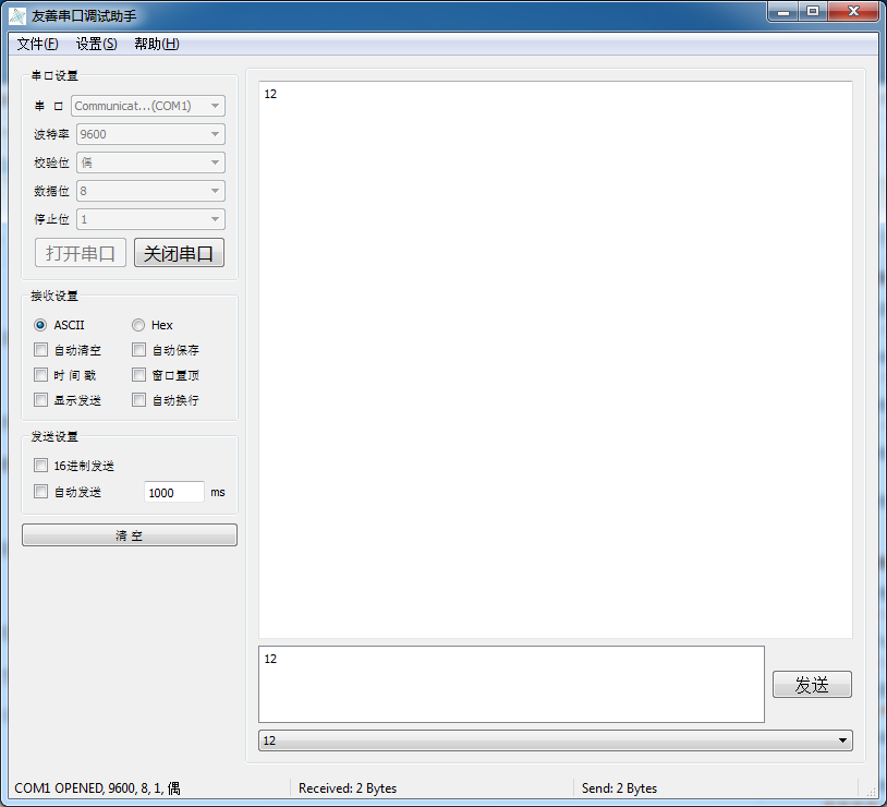
模式:9600-8- even-1。
程序简介:
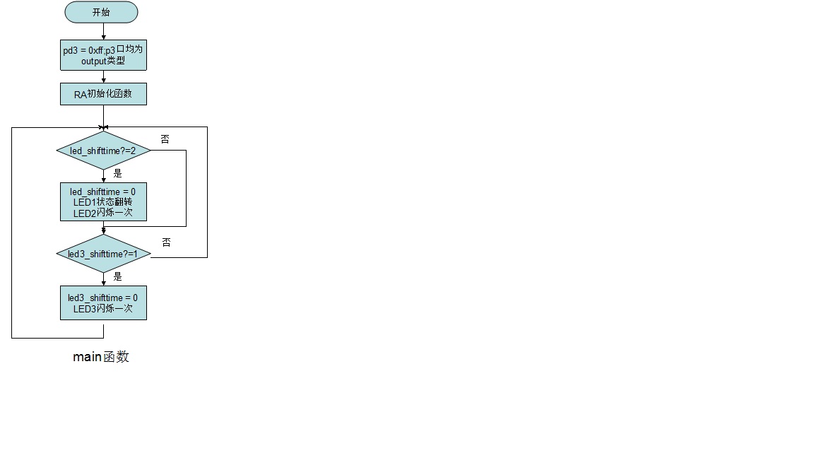
void main(void)
{
clk_set(); //设置时钟为无分频外部晶振
port_cfg(); //设置I/O口P0_1/TXD1为输出端口、P0_2为/RXD1为输入端口
uart_intial(); //UART1 初始化设置
rcv_cnt = 0; //接收字符个数清零
ENABLE_IRQ; // 允许中断
}
/**********************************************************************
* Function Name: uart_intial()
* Description: Set UART1:9600-8-N-1.
* Note: None
* Parameters: None.
* Returns: None
* Ext. References: None
* Preemptible: No.
* Reentrant: No.
*********************************************************************/
void uart_intial(void)
{
txd1sel0 = 1;
txd1sel1 = 0; //选择P0_1为 TXD1
rxd1sel0 = 1;
rxd1sel1 = 0; //选择P0_2为 RXD1
clk1sel0 = 1;
clk1sel1 = 0; //选择P0_3为CLK1
smd2_u1mr = 1;
smd1_u1mr = 0;
smd0_u1mr = 1; //UART mode, transfer data 8 bits long
ckdir_u1mr = 0; //select Internal clock
stps_u1mr = 0; //1 stop bit
pry_u1mr = 1; //Even 校验
prye_u1mr = 1; //校验使能
clk0_u1c0 = 0;
clk1_u1c0 = 0; //选择f1作为BRG count source
u1brg = 129; // bit rate 9600bps
te_u1c1 = 1; //UART1 Transmit enable
re_u1c1 = 1; //UART1 receive enable
u1irs_u1c1 = 0; //选择trans buffer empty(TI=1)作为UART1 transmit中断源
u1rrm_u1c1 = 0; //continuous receive mode disabled
ilvl0_s1ric = 1;
ilvl1_s1ric = 1;
ilvl2_s1ric = 1;//UART1 receive inttupt priotity为7,最高中断优先级
IPL_0; // IPL=0,即响应所有优先级别的中断
}
/**********************************************************************
* Function Name: uart1_receive()
* Description: Reback the data to PC port with UART1.
* Note: None
* Parameters: None.
* Returns: None
* Ext. References: None
* Preemptible: No.
* Reentrant: No.
*********************************************************************/
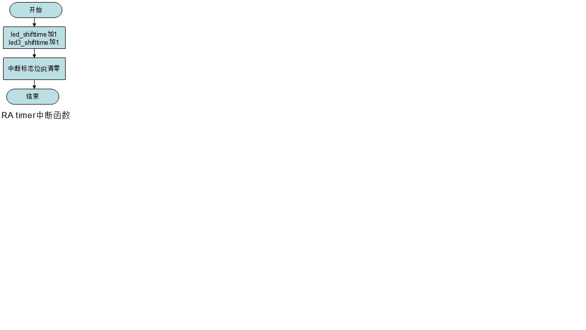
// UART1 receive (software int 20)
#pragma interrupt uart1_receive(vect=20)
void uart1_receive(void)
{
LED2 =!LED2; //LED2闪烁一次
ir_s1ric = 0; //IR清零
rcv_work = u1rb; // Copy character from UART buffer to rcv_work变量
if (++rcv_cnt >= 8)
{
rcv_cnt = 0;
}
uart1receive_buff[rcv_cnt] = (unsigned char) rcv_work;
while(ti_u1c1 == 0)
{
//Wait for transmit buffer is empty
}
u1tbl = uart1receive_buff[rcv_cnt]; //把单片机接收到的重新传给PC
}
运行效果:

并且每接收一个字符,LED2灯闪烁一次。

 我要赚赏金
我要赚赏金 STM32
STM32 MCU
MCU 通讯及无线技术
 物联网技术
物联网技术 电子DIY
电子DIY 板卡试用
板卡试用 基础知识
基础知识 软件与操作系统
 我爱生活
我爱生活 小e食堂
小e食堂

