
为AM335x移植Linux内核主线代码
一、了解dts
问题一:以前的Linux Kernel如何描述硬件,现在又如何描述呢?
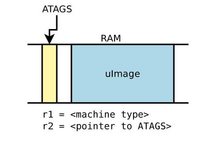
在以前的内核版本中:
1)内核包含了对硬件的全部描述;
2)bootloader会加载一个二进制的内核镜像,并执行它,比如uImage或者zImage;
3)bootloader会提供一些额外的信息,成为ATAGS,它的地址会通过r2寄存器传给内核;
ATAGS包含了内存大小和地址,kernel command line等等;
4)bootloader会告诉内核加载哪一款board,通过r1寄存器存放的machine type integer;
5)U-Boot的内核启动命令:bootm
6)Barebox变量:bootm.image (?)
6)Barebox变量:bootm.image,bootm.oftree
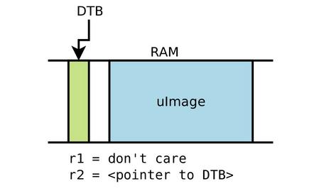
有些bootloader不支持Device Tree,或者有些专门给特定设备写的版本太老了,也不包含。为了解决这个问题,CONFIG_ARM_APPENDED_DTB被引进。
它告诉内核,在紧跟着内核的地址里查找DTB文件;
由于没有built-in Makefile rule来产生这样的内核,因此需要手动操作:
cat arch/arm/boot/zImage arch/arm/boot/dts/myboard.dtb > my-zImage
mkimage ... -d my-zImage my-uImage
(cat这个命令,还能够直接合并两个mp3文件哦!so easy!)
另外,CONFIG_ARM_ATAG_DTB_COMPAT选项告诉内核去bootloader里面读取ATAGS,并使用它们升级DT。
=============================================
问题二:现在Linux Kernel使用的Device Tree到底是个什么东东?
引用the Power.org Standard for Embedded Power Architecture Platform Requirements (ePAPR)的定义:
1)ePAPR使用device tree的概念描述硬件。boot程序会加载device tree到client program's memory中,并将device tree的指针传递给client;
2)device tree是一个树形数据结构with nodes,用来描述系统的physical devices;
3)一个ePAPR-complient device tree描述的设备信息不能被client program读取;
From Source to binary
1)在ARM系统中,所有的DTS文件放置在arch/arm/boot/dts中:
.dts文件为板级定义
.dtsi文件为SoC级定义
2)Device Tree Compiler工具,将源代码编译成二进制形式;
它的源代码放置在scripts/dtc中
3)编译器会产生DTB文件,bootloader会加载这个DTB文件,内核在boot时去解析它;
4)arch/arm/boot/dts/Makefile会指定产生哪个DTB文件;
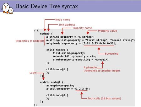
上图是pdf里面自带的例子,我再从arch/arm/boot/dts/am33xxx.dtsi中摘录了两个:
 uart0: serial@44e09000 {
                        compatible = "ti,omap3-uart";
                        ti,hwmods = "uart1";
                        clock-frequency =;
                        reg =;
                        interrupts =;
                        status = "disabled";
                };

                uart1: serial@48022000 {
                        compatible = "ti,omap3-uart";
                        ti,hwmods = "uart2";
                        clock-frequency =;
                        reg =;
                        interrupts =;
                        status = "disabled";
                };
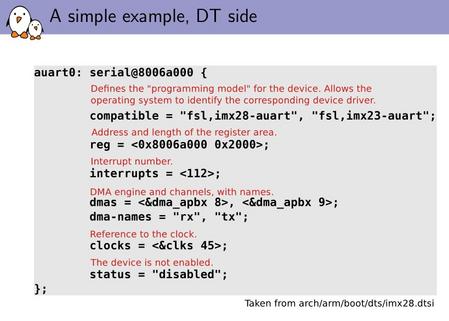
对比图片中的注释,就能够知道对于uart0这个外设:
Node name: serial
Unit Address: 0x44e09000
compatible: 定义了设备的programming model,允许操作系统识别对应的程序驱动;
clock-frequency: 48000000,晶振频率为24MHz,这应该是PLL倍频后的输出(?);
reg: 寄存器的地址和寄存器长度,uart0的地址起始为0x44e09000,长度为0x2000;
interrupts: 中断号;
status: 状态值,初始的时候为disabled,即禁用它;
=============================================
问题三:Device Tree的编写规则是怎样的?
1)Device Tree inclusion不一定要做成monolithic,它们可以分散在不同的文件中,互相包含;
2).dtsi文件是被包含的,.dts文件才是最终的Device Trees;
3).dts文件包含了板级信息;
4)including工作主要是将including file覆盖到included file上面;
5)inclusion使用DT操作符/include/,或者在某些少量的内核发布版中,由于DTS是使用了C preprocessor,因此推荐#include。
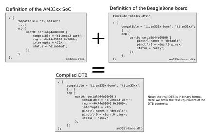
由这张图可见,如果included file中的某项,被including file文件定义了,则会使用后者的定义,也就是使用更上层更新的定义;如果没有被定义,则添加进入。
1)bindings是device tree里面可已包含的specific types and classes of devices。
2)compatible特征描述了节点编译的specific binding;
3)当为一个设备创建新的device tree时,应该创建a binding来描述设备的全部细节。
=============================================
问题四:在哪里可以找到Device Tree的文档呢?
1)所有可被内核识别的Device Tree bindings在文档Documentation/devicetree/bindings里面;
2)每个binding文档描述了哪些properties可以被接受,可以使用哪些值,哪些特征是必须的,哪些是可选的;
3)所有新的Device Tree bindings必须让代码维护者审核,提交到devicetree@vger.kernel.org上。这用来保证它们的正确性和一致性。
=============================================
问题五:Device Tree中的常见关键字含义是什么?
Device Tree organization: top-level nodes
在设备的最顶层节点上,一般可以发现如下这些:
cpus:描述了系统的CPU
memory:定义了RAM的地址和大小
chosen:定义了boot时被系统固件选择或定义的参数;可用来传递kernel command line;
aliases:定义了certain nodes的shotcuts;
一个或多个总线定义;
一个或多个板上设备定义;
下面是am33xx.dtsi中的定义:
/ {
        compatible = "ti,am33xx";
        interrupt-parent = <&intc>;

        aliases {
                i2c0 = &i2c0;
                i2c1 = &i2c1;
                i2c2 = &i2c2;
                serial0 = &uart0;
                serial1 = &uart1;
                serial2 = &uart2;
                serial3 = &uart3;
                serial4 = &uart4;
                serial5 = &uart5;
                d_can0 = &dcan0;
                d_can1 = &dcan1;
                usb0 = &usb0;
                usb1 = &usb1;
                phy0 = &usb0_phy;
                phy1 = &usb1_phy;
                ethernet0 = &cpsw_emac0;
                ethernet1 = &cpsw_emac1;
        };

        cpus {
                #address-cells =;
                #size-cells =;
                cpu@0 {
                        compatible = "arm,cortex-a8";
                        device_type = "cpu";
                        reg =;

                        /*
                         * To consider voltage drop between PMIC and SoC,
                         * tolerance value is reduced to 2% from 4% and
                         * voltage value is increased as a precaution.
                         */
                        operating-points = <
                                /* kHz    uV */
                                720000  1285000
                                600000  1225000
                                500000  1125000
                                275000  1125000
                        >;
                        voltage-tolerance =; /* 2 percentage */

                        clocks = <&dpll_mpu_ck>;
                        clock-names = "cpu";

                        clock-latency =; /* From omap-cpufreq driver */
                };
        };

        pmu {
                compatible = "arm,cortex-a8-pmu";
                interrupts =;
        };

        /*
         * The soc node represents the soc top level view. It is used for IPs
         * that are not memory mapped in the MPU view or for the MPU itself.
         */
        soc {
                compatible = "ti,omap-infra";
                mpu {
                        compatible = "ti,omap3-mpu";
                        ti,hwmods = "mpu";
                };
        };


    /* ...... */

};
从上面的代码里面可以找出四个compatible,分别是:
top: compatible = "ti,am33xx";
cpu0: compatible = "arm,cortex-a8";
pmu: compatible = "arm,cortex-a8-pmu";
soc: compatible = "ti,omap-infra";
怎样使用compatible呢?
方法一是用来匹配DT_MACHINE结构体中的dt_compat域,方法二是使用of_machine_is_compatible函数。
在总线中,一般要定义compatile、#address-cells、#size-cells、ranges,比如:
 i2c0: i2c@44e0b000 {
                compatible = "ti,omap4-i2c";
                #address-cells =;
                #size-cells =;
                ti,hwmods = "i2c1";
                reg =;
                interrupts =;
                status = "disabled";
        };
&ldo3_reg是tps65217其中的一个输出。此描述表示tps65217的LDO3输出电平范围为1.8V~3.3V,并一直打开。
&sham 表示 SHA crypto Module!
&aes 表示 AES crypto Module!
(****找了半天也不知道这俩个东东到底是神马~?内存映射里面它们的地址也是reserved!)
<<<<<<<<<<<<<<<<<<<<<<<<<<<<<<<<<<<<<<<<<
总结:
maria_am335x.dts的内容非常少,因为大部分的描述并没有放置在这里,而是在更底层;
如果在这个文件里加入从未有过的描述,则描述会被添加;
如果在这个文建立加入底层已有的描述,则描述会覆盖底层;
这样的策略保证了底层的通用代码基本不需要修改,all you have to do,就是更改和你的板子相关的两个文件xx.dts和xx-common.dts!
(文章转载自edn博客 作者:MariannaZhu )

 我要赚赏金
我要赚赏金 STM32
STM32 MCU
MCU 通讯及无线技术
 物联网技术
物联网技术 电子DIY
电子DIY 板卡试用
板卡试用 基础知识
基础知识 软件与操作系统
 我爱生活
我爱生活 小e食堂
小e食堂

