
PWM-ADC调节RGB
这次ADC控制RGB色彩与亮度的程序是在之前PWM的程序的基础上做的。
鉴于视频不能把ADC控制RGB时,三盏LED的微妙变化细致地拍摄出来,在此解说一下视频的内容。
当temp的值为0时led亮起,temp的值大于等于2047时led才会完全灭掉。
当0<=temp<2047 时led是亮起的,具体亮度由temp值决定,temp值越小led越亮。
temp>=2047 时led是熄灭的。
我自己定义的变量volt是Volt的1000倍,我把volt的值作为temp0,temp1,temp2的变化上限。也就是说 temp0,temp1,temp2 是在0到volt之间增减的。
1、视频中我首先把可调电阻顺时针旋转到底,Volt=0.0 v,volt=0
所以temp0,temp1,temp2 在0到0之间,因此三个变量一直为0,体现出来的效果就是三盏led均以最高亮度亮起,呈现白光。
2、然后我把可调电阻逆时针旋转到底,Volt=3.3 v,volt=3300.
此时temp0,temp1,temp2 在0到3300之间增减,效果就是RGB渐变出各种颜色,不过蓝红绿比较明显,混合色不明显。
3、我又把旋钮顺时针旋转了一点点,Volt=2.111,volt=2111,2111略大于2047,所以混合色的效果比之前的3300要明显多了。
4、最后我又顺时针旋转了一些,Volt=1.595 ,volt=1595,1595小于2047,因此三盏led都不会熄灭,只是亮度稍有变化,RGB整体是呈现白光的。
#include "stm32f10x.h"
#include "stm32_eval.h"
#include <stdio.h>
#define VREF 3.3
GPIO_InitTypeDef   GPIO_InitStructure;
USART_InitTypeDef USART_InitStructure;
USART_ClockInitTypeDef USART_ClockInitStructure;
int volt;
unsigned int temp0,temp1,temp2;
void RCC_Configuration(void)
{/*
  RCC_DeInit();

  RCC_HSICmd(ENABLE);
  while(RCC_GetFlagStatus(RCC_FLAG_HSIRDY) == RESET);

  RCC_SYSCLKConfig(RCC_SYSCLKSource_HSI);

  RCC_HSEConfig(RCC_HSE_OFF);
  RCC_LSEConfig(RCC_LSE_OFF);
  RCC_PLLConfig(RCC_PLLSource_HSI_Div2,RCC_PLLMul_9); //  72HMz
  RCC_PLLCmd(ENABLE);
  while(RCC_GetFlagStatus(RCC_FLAG_PLLRDY) == RESET);
  RCC_ADCCLKConfig(RCC_PCLK2_Div4);
  RCC_PCLK2Config(RCC_HCLK_Div1);
  RCC_PCLK1Config(RCC_HCLK_Div2);
  RCC_HCLKConfig(RCC_SYSCLK_Div1);
  RCC_SYSCLKConfig(RCC_SYSCLKSource_PLLCLK);
  while(RCC_GetSYSCLKSource() != 0x08);
*/
	SystemInit();
	RCC_APB2PeriphClockCmd(RCC_APB2Periph_GPIOD|RCC_APB2Periph_AFIO, ENABLE);
 GPIO_PinRemapConfig(GPIO_Remap_SWJ_JTAGDisable,ENABLE);//disable JTAG
RCC_APB2PeriphClockCmd(RCC_APB2Periph_GPIOD|RCC_APB2Periph_AFIO, ENABLE);
 GPIO_PinRemapConfig(GPIO_Remap_SWJ_JTAGDisable,ENABLE);//disable JTAG
  GPIO_InitStructure.GPIO_Pin = GPIO_Pin_2;
  GPIO_InitStructure.GPIO_Speed = GPIO_Speed_50MHz;
  GPIO_InitStructure.GPIO_Mode = GPIO_Mode_Out_PP;
  GPIO_Init(GPIOD, &GPIO_InitStructure);
	GPIO_ResetBits(GPIOD,GPIO_Pin_2);
	RCC_APB2PeriphClockCmd(RCC_APB2Periph_GPIOC|RCC_APB2Periph_AFIO, ENABLE);
 GPIO_PinRemapConfig(GPIO_Remap_SWJ_JTAGDisable,ENABLE);//disable JTAG
  GPIO_InitStructure.GPIO_Pin = GPIO_Pin_0|GPIO_Pin_1|GPIO_Pin_2|GPIO_Pin_3|GPIO_Pin_4|GPIO_Pin_5|GPIO_Pin_6|GPIO_Pin_7;
  GPIO_InitStructure.GPIO_Speed = GPIO_Speed_50MHz;
  GPIO_InitStructure.GPIO_Mode = GPIO_Mode_Out_PP;
  GPIO_Init(GPIOC, &GPIO_InitStructure);
	GPIO_SetBits(GPIOC,GPIO_Pin_0|GPIO_Pin_1|GPIO_Pin_2|GPIO_Pin_3|GPIO_Pin_4|GPIO_Pin_5|GPIO_Pin_6|GPIO_Pin_7);
	  RCC_APB1PeriphClockCmd(RCC_APB1Periph_TIM2, ENABLE);
}

void USART_int(long BaudRate)
{
	RCC_APB2PeriphClockCmd(RCC_APB2Periph_GPIOA|RCC_APB2Periph_USART1,ENABLE);
       GPIO_InitStructure.GPIO_Pin = GPIO_Pin_9;
    GPIO_InitStructure.GPIO_Speed = GPIO_Speed_10MHz;
    GPIO_InitStructure.GPIO_Mode = GPIO_Mode_AF_PP;
    GPIO_Init(GPIOA, &GPIO_InitStructure);
    /* PA10 USART1_Rx  */
    GPIO_InitStructure.GPIO_Pin = GPIO_Pin_10;
    GPIO_InitStructure.GPIO_Mode = GPIO_Mode_IN_FLOATING;
    GPIO_Init(GPIOA, &GPIO_InitStructure);
  /* USARTx configured as follow:
        - BaudRate = 115200 baud
        - Word Length = 8 Bits
        - One Stop Bit
        - No parity
        - Hardware flow control disabled (RTS and CTS signals)
        - Receive and transmit enabled
  */
  USART_InitStructure.USART_BaudRate = BaudRate;//??????
  USART_InitStructure.USART_WordLength = USART_WordLength_8b;//???????8bit
  USART_InitStructure.USART_StopBits = USART_StopBits_1;//????1
  USART_InitStructure.USART_Parity = USART_Parity_No;//????
  USART_InitStructure.USART_HardwareFlowControl = USART_HardwareFlowControl_None;//??????none
  USART_InitStructure.USART_Mode = USART_Mode_Rx | USART_Mode_Tx;//??????????
	USART_ClockInitStructure.USART_Clock = USART_Clock_Disable;
    USART_ClockInitStructure.USART_CPOL = USART_CPOL_Low;
    USART_ClockInitStructure.USART_CPHA = USART_CPHA_2Edge;
    USART_ClockInitStructure.USART_LastBit = USART_LastBit_Disable;
    USART_ClockInit(USART1, &USART_ClockInitStructure);
  USART_Init(USART1, &USART_InitStructure);
  USART_Cmd(USART1, ENABLE);
	USART_ITConfig(USART1, USART_IT_RXNE, ENABLE);
 USART_Cmd(USART1, ENABLE);
}
void delay_us(u32 n)
{
	u8 j;
	while(n--)
	for(j=0;j<10;j++);
}
void  delay_ms(u32 n)
{
	while(n--)
	delay_us(1000);
}
void PWM_Config()
{
	uint16_t PrescalerValue = 0;
	TIM_TimeBaseInitTypeDef  TIM_TimeBaseStructure;
  TIM_OCInitTypeDef  TIM_OCInitStructure;
	/* TIM2 clock enable */
  RCC_APB1PeriphClockCmd(RCC_APB1Periph_TIM2, ENABLE);
  /* GPIOA  enable */
  RCC_APB2PeriphClockCmd(RCC_APB2Periph_AFIO, ENABLE);
	GPIO_InitStructure.GPIO_Pin = GPIO_Pin_1|GPIO_Pin_2|GPIO_Pin_3;//PWM&RGB- PA1 PA2 PA3
  GPIO_InitStructure.GPIO_Mode = GPIO_Mode_AF_PP;
  GPIO_InitStructure.GPIO_Speed = GPIO_Speed_50MHz;
  GPIO_Init(GPIOA, &GPIO_InitStructure);
		TIM_Cmd(TIM2, ENABLE);
	  /* Compute the prescaler value */
  PrescalerValue = (uint16_t) (SystemCoreClock / 24000000) - 1;
  /* Time base configuration */
  TIM_TimeBaseStructure.TIM_Period = 0x07FF;
  TIM_TimeBaseStructure.TIM_Prescaler = PrescalerValue;
  TIM_TimeBaseStructure.TIM_ClockDivision = 0;
  TIM_TimeBaseStructure.TIM_CounterMode = TIM_CounterMode_Up;
  TIM_TimeBaseInit(TIM2, &TIM_TimeBaseStructure);
  TIM_OCInitStructure.TIM_OCMode = TIM_OCMode_PWM1;
  TIM_OCInitStructure.TIM_OCPolarity = TIM_OCPolarity_High;
  /* PWM1 Mode configuration: Channel2 ,PA1在通道2*/
  TIM_OCInitStructure.TIM_OutputState = TIM_OutputState_Enable;
  TIM_OCInitStructure.TIM_Pulse = 0xFFFF;
  TIM_OC2Init(TIM2, &TIM_OCInitStructure);
	/* PWM1 Mode configuration: Channel3 PA2在通道3*/
  TIM_OCInitStructure.TIM_OutputState = TIM_OutputState_Enable;
  TIM_OCInitStructure.TIM_Pulse = 0xFFFF;
  TIM_OC3Init(TIM2, &TIM_OCInitStructure);
	/* PWM1 Mode configuration: Channel4 PA3在通道4*/
  TIM_OCInitStructure.TIM_OutputState = TIM_OutputState_Enable;
  TIM_OCInitStructure.TIM_Pulse = 0xFFFF;
  TIM_OC4Init(TIM2, &TIM_OCInitStructure);
  TIM_ARRPreloadConfig(TIM2, ENABLE);
}
void ADC_CONFIG(){
	ADC_InitTypeDef ADC_InitStructure;
	#if defined (STM32F10X_LD_VL) || defined (STM32F10X_MD_VL) || defined (STM32F10X_HD_VL)
  /* ADCCLK = PCLK2/2 */
  RCC_ADCCLKConfig(RCC_PCLK2_Div2);
#else
  /* ADCCLK = PCLK2/4 */
  RCC_ADCCLKConfig(RCC_PCLK2_Div4);
#endif
ADC_DeInit(ADC1);
  /* Enable ADC1 and GPIOC clock */
  RCC_APB2PeriphClockCmd(RCC_APB2Periph_ADC1 | RCC_APB2Periph_GPIOB, ENABLE);
	/* Configure PB0 (ADC Channel14) as analog input -------------------------*/
  GPIO_InitStructure.GPIO_Pin = GPIO_Pin_0;//ADC所在端口PB0
  GPIO_InitStructure.GPIO_Mode = GPIO_Mode_AIN;//模拟输入模式
  GPIO_Init(GPIOB, &GPIO_InitStructure);
  /* ADC1 configuration ------------------------------------------------------*/
  ADC_InitStructure.ADC_Mode = ADC_Mode_Independent;
  ADC_InitStructure.ADC_ScanConvMode = ENABLE;
  ADC_InitStructure.ADC_ContinuousConvMode = ENABLE;
  ADC_InitStructure.ADC_ExternalTrigConv = ADC_ExternalTrigConv_None;
  ADC_InitStructure.ADC_DataAlign = ADC_DataAlign_Right;//ADC数据右对齐
  ADC_InitStructure.ADC_NbrOfChannel = 1;//ADC通道数为1
  ADC_Init(ADC1, &ADC_InitStructure);//初始化ADC1
  /* Enable ADC1 DMA */
  ADC_DMACmd(ADC1, ENABLE);
  /* Enable ADC1 */
  ADC_Cmd(ADC1, ENABLE);
}

int Get_ADC(){
	 /* ADC1 regular channel configuration */
  ADC_RegularChannelConfig(ADC1, ADC_Channel_8, 1, ADC_SampleTime_55Cycles5);//通道:8 ,采样时间
	/* Enable ADC1 reset calibration register */
  ADC_ResetCalibration(ADC1);//重置ADC1的校准寄存器
  /* Check the end of ADC1 reset calibration register */
  while(ADC_GetResetCalibrationStatus(ADC1));//确认重置完毕
  /* Start ADC1 calibration */
  ADC_StartCalibration(ADC1);//开始ADC1校准
  /* Check the end of ADC1 calibration */
  while(ADC_GetCalibrationStatus(ADC1));//确认校准完毕
  /* Start ADC1 Software Conversion */
  ADC_SoftwareStartConvCmd(ADC1, ENABLE);//使能ADC1软件转换功能
	return ADC_GetConversionValue(ADC1);
}
void PWM_TEST()
{
	/*全局变量volt,控制TIM_SetCompare2,TIM_SetCompare3,TIM_SetCompare4 的第二个参数*/
	unsigned int temp0=volt,temp1=0,temp2=volt;
	printf("PWM-RGB TEST......\r\n");
   for(;(temp0>0)||(temp1<volt);temp0--,temp1++)// ???? ????
   {
	   TIM_SetCompare2(TIM2, temp0);//temp0:volt~0
     TIM_SetCompare3(TIM2, temp1);//temp1:0~volt
	   delay_us(1000);
   }
	 for(;(temp0<volt)||(temp2>0);temp0++,temp2--)//????  ????
	 {
	   TIM_SetCompare2(TIM2, temp0);//temp0:0~volt
	   TIM_SetCompare4(TIM2, temp2);//temp2:volt~0
	   delay_us(1000);
   }
   for(;(temp1>0)||(temp2<volt);temp1--,temp2++)//???? ????
   {
	   TIM_SetCompare4(TIM2, temp2);//temp2:0~volt
	   TIM_SetCompare3(TIM2, temp1);//temp1:volt~0
	   delay_us(1000);
   }
}
int main(void)
{
  float Volt=0.00;
	int ADValue = 0;
  RCC_Configuration();
  USART_int(115200);
	ADC_CONFIG();
	Get_ADC();
	PWM_Config();
	delay_ms(1000);
	printf(" config done...\r\n");
	while(1)
	{
		ADValue = Get_ADC();
		Volt = VREF*ADValue/4095;
		/*volt的值由Volt直接决定 volt是Volt乘以1000的整型值*/
		volt=Volt*1000;
		printf("===============================\r\n");
		printf("The ADC value is:%d\r\n",ADValue);
		printf("The Volt is:%f V\r\n",Volt);
		printf("The volt is:%d \r\n",volt);
		PWM_TEST();
		delay_ms(500);
	}
}

#ifdef  USE_FULL_ASSERT

void assert_failed(uint8_t* file, uint32_t line)
{
  while (1)
  {
  }
}

#endif

#ifdef __GNUC__
  #define PUTCHAR_PROTOTYPE int __io_putchar(int ch)
#else
  #define PUTCHAR_PROTOTYPE int fputc(int ch, FILE *f)
#endif /* __GNUC__ */

PUTCHAR_PROTOTYPE
{

  USART_SendData(EVAL_COM1, (uint8_t) ch);
  while (USART_GetFlagStatus(EVAL_COM1, USART_FLAG_TC) == RESET)
  {}

  return ch;
}

#ifdef  USE_FULL_ASSERT

void assert_failed(uint8_t* file, uint32_t line)
{
  while (1)
  {
  }
}
#endif
IIC-计上电次数

#include "stm32f10x.h"
#include "stm32_eval.h"
#include "STM32_I2C.h"
#include <stdio.h>

GPIO_InitTypeDef   GPIO_InitStructure;
USART_InitTypeDef USART_InitStructure;
USART_ClockInitTypeDef USART_ClockInitStructure;
EXTI_InitTypeDef   EXTI_InitStructure;
NVIC_InitTypeDef   NVIC_InitStructure;
unsigned char i;
void EXTIkeyS1_Config(void);

/*delay_us*/
void delay_us(u32 n)
{
	u8 j;
	while(n--)
	for(j=0;j<10;j++);
}
/*delay_ms*/

void  delay_ms(u32 n)
{
	while(n--)
	delay_us(1000);
}

void RCC_Configuration(void)
{
  RCC_DeInit();
  RCC_HSICmd(ENABLE);
  while(RCC_GetFlagStatus(RCC_FLAG_HSIRDY) == RESET);
  RCC_SYSCLKConfig(RCC_SYSCLKSource_HSI);
  RCC_HSEConfig(RCC_HSE_OFF);
  RCC_LSEConfig(RCC_LSE_OFF);
  RCC_PLLConfig(RCC_PLLSource_HSI_Div2,RCC_PLLMul_9); //  72HMz
  RCC_PLLCmd(ENABLE);
  while(RCC_GetFlagStatus(RCC_FLAG_PLLRDY) == RESET);
  RCC_ADCCLKConfig(RCC_PCLK2_Div4);
  RCC_PCLK2Config(RCC_HCLK_Div1);
  RCC_PCLK1Config(RCC_HCLK_Div2);
  RCC_HCLKConfig(RCC_SYSCLK_Div1);
  RCC_SYSCLKConfig(RCC_SYSCLKSource_PLLCLK);
  while(RCC_GetSYSCLKSource() != 0x08);
	//SystemInit();
	RCC_APB2PeriphClockCmd(RCC_APB2Periph_GPIOD|RCC_APB2Periph_AFIO, ENABLE);
  GPIO_PinRemapConfig(GPIO_Remap_SWJ_JTAGDisable,ENABLE);//disable JTAG
  RCC_APB2PeriphClockCmd(RCC_APB2Periph_GPIOD|RCC_APB2Periph_AFIO, ENABLE);
  GPIO_PinRemapConfig(GPIO_Remap_SWJ_JTAGDisable,ENABLE);//disable JTAG
  GPIO_InitStructure.GPIO_Pin = GPIO_Pin_2;
  GPIO_InitStructure.GPIO_Speed = GPIO_Speed_50MHz;
  GPIO_InitStructure.GPIO_Mode = GPIO_Mode_Out_PP;
  GPIO_Init(GPIOD, &GPIO_InitStructure);
	GPIO_ResetBits(GPIOD,GPIO_Pin_2);
	RCC_APB2PeriphClockCmd(RCC_APB2Periph_GPIOC|RCC_APB2Periph_AFIO, ENABLE);
  GPIO_PinRemapConfig(GPIO_Remap_SWJ_JTAGDisable,ENABLE);//disable JTAG
  GPIO_InitStructure.GPIO_Pin = GPIO_Pin_0|GPIO_Pin_1|GPIO_Pin_2|GPIO_Pin_3|GPIO_Pin_4|GPIO_Pin_5|GPIO_Pin_6|GPIO_Pin_7;
  GPIO_InitStructure.GPIO_Speed = GPIO_Speed_50MHz;
  GPIO_InitStructure.GPIO_Mode = GPIO_Mode_Out_PP;
  GPIO_Init(GPIOC, &GPIO_InitStructure);
	GPIO_SetBits(GPIOC,GPIO_Pin_0|GPIO_Pin_1|GPIO_Pin_2|GPIO_Pin_3|GPIO_Pin_4|GPIO_Pin_5|GPIO_Pin_6|GPIO_Pin_7);
	  RCC_APB1PeriphClockCmd(RCC_APB1Periph_TIM2, ENABLE);
}

void USART_int(long BaudRate)
{
	  RCC_APB2PeriphClockCmd(RCC_APB2Periph_GPIOA|RCC_APB2Periph_USART1,ENABLE);
    GPIO_InitStructure.GPIO_Pin = GPIO_Pin_9;
    GPIO_InitStructure.GPIO_Speed = GPIO_Speed_50MHz;
    GPIO_InitStructure.GPIO_Mode = GPIO_Mode_AF_PP;
    GPIO_Init(GPIOA, &GPIO_InitStructure);
    /* PA10 USART1_Rx  */
    GPIO_InitStructure.GPIO_Pin = GPIO_Pin_10;
    GPIO_InitStructure.GPIO_Mode = GPIO_Mode_IN_FLOATING;
    GPIO_Init(GPIOA, &GPIO_InitStructure);
  /* USARTx configured as follow:
        - BaudRate = 115200 baud
        - Word Length = 8 Bits
        - One Stop Bit
        - No parity
        - Hardware flow control disabled (RTS and CTS signals)
        - Receive and transmit enabled
  */
  USART_InitStructure.USART_BaudRate = BaudRate;//??????
  USART_InitStructure.USART_WordLength = USART_WordLength_8b;//???????8bit
  USART_InitStructure.USART_StopBits = USART_StopBits_1;//????1
  USART_InitStructure.USART_Parity = USART_Parity_No;//????
  USART_InitStructure.USART_HardwareFlowControl = USART_HardwareFlowControl_None;//??????none
  USART_InitStructure.USART_Mode = USART_Mode_Rx | USART_Mode_Tx;//??????????
	USART_ClockInitStructure.USART_Clock = USART_Clock_Disable;
    USART_ClockInitStructure.USART_CPOL = USART_CPOL_Low;
    USART_ClockInitStructure.USART_CPHA = USART_CPHA_2Edge;
    USART_ClockInitStructure.USART_LastBit = USART_LastBit_Disable;
    USART_ClockInit(USART1, &USART_ClockInitStructure);
  USART_Init(USART1, &USART_InitStructure);
  USART_Cmd(USART1, ENABLE);
	USART_ITConfig(USART1, USART_IT_RXNE, ENABLE);
  USART_Cmd(USART1, ENABLE);
	  /* Configure four bit for preemption priority */
  NVIC_PriorityGroupConfig(NVIC_PriorityGroup_4);
  /* Enable the USART1 Interrupt */
  NVIC_InitStructure.NVIC_IRQChannel = USART1_IRQn; //
  NVIC_InitStructure.NVIC_IRQChannelPreemptionPriority = 15;
  NVIC_InitStructure.NVIC_IRQChannelCmd = ENABLE;
  NVIC_Init(&NVIC_InitStructure);
}

void IIc2_Init(void)
{
        GPIO_InitTypeDef GPIO_InitStructure;
        I2C_InitTypeDef I2C_InitStructure;

        RCC_APB2PeriphClockCmd(RCC_APB2Periph_GPIOB, ENABLE);
        RCC_APB1PeriphClockCmd(RCC_APB1Periph_I2C2, ENABLE);
        //PB6-I2C2_SCL PB7-I2C2_SDA PB10-I2C2_SCL PB11-I2C2_SDA
        /* Configure IO connected to IIC*********************/
        GPIO_InitStructure.GPIO_Pin =  GPIO_Pin_10 | GPIO_Pin_11;
        GPIO_InitStructure.GPIO_Speed = GPIO_Speed_50MHz;
        GPIO_InitStructure.GPIO_Mode = GPIO_Mode_AF_OD;
        GPIO_Init(GPIOB, &GPIO_InitStructure);

        I2C_InitStructure.I2C_Mode = I2C_Mode_I2C;
        I2C_InitStructure.I2C_DutyCycle = I2C_DutyCycle_2;
        I2C_InitStructure.I2C_OwnAddress1 = 0xA0;
        I2C_InitStructure.I2C_Ack = I2C_Ack_Enable;
        I2C_InitStructure.I2C_AcknowledgedAddress = I2C_AcknowledgedAddress_7bit;
        I2C_InitStructure.I2C_ClockSpeed = 400000;
        I2C_Cmd(I2C2, ENABLE);
        I2C_Init(I2C2, &I2C_InitStructure);
        I2C_AcknowledgeConfig(I2C2, ENABLE);
}

void I2C2_WriteByte(unsigned char id,unsigned char write_address,unsigned char byte)
{
        while(I2C_GetFlagStatus(I2C2, I2C_FLAG_BUSY));
        I2C_GenerateSTART(I2C2,ENABLE);
        while(!I2C_CheckEvent(I2C2, I2C_EVENT_MASTER_MODE_SELECT));
        I2C_Send7bitAddress(I2C2,id,I2C_Direction_Transmitter);
        while(!I2C_CheckEvent(I2C2, I2C_EVENT_MASTER_TRANSMITTER_MODE_SELECTED));
        I2C_SendData(I2C2, write_address);
        while(!I2C_CheckEvent(I2C2, I2C_EVENT_MASTER_BYTE_TRANSMITTED));
        I2C_SendData(I2C2, byte);
        while(!I2C_CheckEvent(I2C2, I2C_EVENT_MASTER_BYTE_TRANSMITTED));
        I2C_GenerateSTOP(I2C2, ENABLE);
        do
        {
           /* Send START condition */
           I2C_GenerateSTART(I2C2, ENABLE);
          /* Read I2C2 SR1 register */
            /* Send EEPROM address for write */
            I2C_Send7bitAddress(I2C2, 0xA0, I2C_Direction_Transmitter);
        }while(!(I2C_ReadRegister(I2C2, I2C_Register_SR1) & 0x0002));

        /* Clear AF flag */
        I2C_ClearFlag(I2C2, I2C_FLAG_AF);
        /* STOP condition */
        I2C_GenerateSTOP(I2C2, ENABLE);
}

unsigned char I2C2_ReadByte(unsigned char  id, unsigned char read_address)
{
     unsigned char temp;
     while(I2C_GetFlagStatus(I2C2, I2C_FLAG_BUSY)){}
     I2C_GenerateSTART(I2C2, ENABLE);
     while(!I2C_CheckEvent(I2C2, I2C_EVENT_MASTER_MODE_SELECT));
     I2C_Send7bitAddress(I2C2, id, I2C_Direction_Transmitter);
     while(!I2C_CheckEvent(I2C2, I2C_EVENT_MASTER_TRANSMITTER_MODE_SELECTED));
     I2C_Cmd(I2C2, ENABLE);
     I2C_SendData(I2C2, read_address);
     while(!I2C_CheckEvent(I2C2, I2C_EVENT_MASTER_BYTE_TRANSMITTED));
     I2C_GenerateSTART(I2C2, ENABLE);
     while(!I2C_CheckEvent(I2C2, I2C_EVENT_MASTER_MODE_SELECT));
     I2C_Send7bitAddress(I2C2, id, I2C_Direction_Receiver);
     while(!I2C_CheckEvent(I2C2, I2C_EVENT_MASTER_RECEIVER_MODE_SELECTED));
    I2C_AcknowledgeConfig(I2C2, DISABLE);
    I2C_GenerateSTOP(I2C2, ENABLE);
    while(!(I2C_CheckEvent(I2C2, I2C_EVENT_MASTER_BYTE_RECEIVED)));
    temp = I2C_ReceiveData(I2C2);
    I2C_AcknowledgeConfig(I2C2, ENABLE);
     return temp;
}

int main(void)
{
  RCC_Configuration();
  EXTIkeyS1_Config();
  USART_int(115200);
  IIc2_Init();
	printf(" config done...\r\n");
	i = I2C2_ReadByte(0xA0,0);//向0x00读取数据
	printf("从地址0x00读出数据 :%d\r\n",i);
	i++;
	I2C2_WriteByte(0xA0,0,i);//向0x00写入数据
	printf("向地址0x00写入数据 :%d\r\n",i);
	while(1)
	{
	 delay_ms(2000);
	 printf(" 上电次数为%d\r\n",i);
	}
}
void EXTIkeyS1_Config(void)//S1 PC8
{
  /* Enable GPIOA clock */
  RCC_APB2PeriphClockCmd(RCC_APB2Periph_GPIOC, ENABLE);
  /* Configure PA.00 pin as input floating */
  GPIO_InitStructure.GPIO_Pin = GPIO_Pin_8;//PC8 S1
  GPIO_InitStructure.GPIO_Mode = GPIO_Mode_IN_FLOATING;
  GPIO_Init(GPIOC, &GPIO_InitStructure);
  /* Enable AFIO clock */
  RCC_APB2PeriphClockCmd(RCC_APB2Periph_AFIO, ENABLE);
  GPIO_EXTILineConfig(GPIO_PortSourceGPIOC, GPIO_PinSource8);
  EXTI_InitStructure.EXTI_Line = EXTI_Line8;
  EXTI_InitStructure.EXTI_Mode = EXTI_Mode_Interrupt;
  EXTI_InitStructure.EXTI_Trigger = EXTI_Trigger_Falling;
  EXTI_InitStructure.EXTI_LineCmd = ENABLE;
  EXTI_Init(&EXTI_InitStructure);
  NVIC_InitStructure.NVIC_IRQChannel = EXTI9_5_IRQn;
  NVIC_InitStructure.NVIC_IRQChannelPreemptionPriority = 0x0F;
  NVIC_InitStructure.NVIC_IRQChannelSubPriority = 0x0F;
  NVIC_InitStructure.NVIC_IRQChannelCmd = ENABLE;
  NVIC_Init(&NVIC_InitStructure);
}
void EXTI9_5_IRQHandler(void)
{
  if(EXTI_GetITStatus(EXTI_Line8) != RESET)
  {
		i=0;
		I2C2_WriteByte(0xA0,0,0);
		printf(" 上电次数为%d\r\n",i);
    /* Clear the  EXTI line 8 pending bit */
    EXTI_ClearITPendingBit(EXTI_Line8);
  }
}

#ifdef  USE_FULL_ASSERT

void assert_failed(uint8_t* file, uint32_t line)
{
  while (1)
  {
  }
}

#endif

#ifdef __GNUC__

  #define PUTCHAR_PROTOTYPE int __io_putchar(int ch)
#else
  #define PUTCHAR_PROTOTYPE int fputc(int ch, FILE *f)
#endif /* __GNUC__ */


PUTCHAR_PROTOTYPE
{

  USART_SendData(EVAL_COM1, (uint8_t) ch);
  while (USART_GetFlagStatus(EVAL_COM1, USART_FLAG_TC) == RESET)
  {}

  return ch;
}

#ifdef  USE_FULL_ASSERT

void assert_failed(uint8_t* file, uint32_t line)
{
  while (1)
  {
  }
}

#endif
系统滴答&18B20
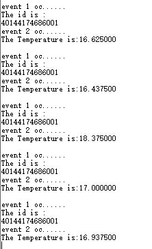
系统时钟配置为48MHZ,由滴答控制,300ms输出一次18B20的ID,500ms输出一次温度。
最开始做的那个程序输出的id一直是乱码,其实是因为打印的时候写了%c,这样写打印出的是字符,打印数字应该写%u。
#include "stm32f10x.h"
#include "stm32_eval.h"
#include <stdio.h>
volatile int flag;
#define Set_B20()	 GPIO_SetBits(GPIOC, GPIO_Pin_12)
#define Reset_B20()	 GPIO_ResetBits(GPIOC, GPIO_Pin_12)
#define Read_B20()	 GPIO_ReadInputDataBit(GPIOC,GPIO_Pin_12)
unsigned char Error_Flag=0;
unsigned char zf=0;
unsigned char ID[8];
void SysTick_Configuration(void)
{
  /* Setup SysTick Timer for 1 msec interrupts  */
  if (SysTick_Config(48000))                //SysTick配置 48000/48MHZ=1ms 滴答一次
  {
    /* Capture error */
    while (1);
  }
 /* Configure the SysTick handler priority */
  NVIC_SetPriority(SysTick_IRQn, 0x0);                       //SysTick中断优先级
}

GPIO_InitTypeDef   GPIO_InitStructure;
USART_InitTypeDef USART_InitStructure;
USART_ClockInitTypeDef USART_ClockInitStructure;
#define RCC_PLLSource_HSE_Div1           ((uint32_t)0x00010000)

void RCC_Configuration(void)
{
  RCC_DeInit();

  RCC_HSICmd(ENABLE);
  while(RCC_GetFlagStatus(RCC_FLAG_HSIRDY) == RESET);

  RCC_SYSCLKConfig(RCC_SYSCLKSource_HSI);

  RCC_HSEConfig(RCC_HSE_OFF);
  RCC_LSEConfig(RCC_LSE_OFF);
  RCC_PLLConfig(RCC_PLLSource_HSI_Div2,RCC_PLLMul_6); // 6*8Mhz= 48MHz
  RCC_PLLCmd(ENABLE);
  while(RCC_GetFlagStatus(RCC_FLAG_PLLRDY) == RESET);
  RCC_ADCCLKConfig(RCC_PCLK2_Div4);
  RCC_PCLK2Config(RCC_HCLK_Div1);
  RCC_PCLK1Config(RCC_HCLK_Div2);
  RCC_HCLKConfig(RCC_SYSCLK_Div1);
  RCC_SYSCLKConfig(RCC_SYSCLKSource_PLLCLK);
  while(RCC_GetSYSCLKSource() != 0x08);
//	SystemInit();
	RCC_APB2PeriphClockCmd(RCC_APB2Periph_GPIOD|RCC_APB2Periph_AFIO, ENABLE);
 GPIO_PinRemapConfig(GPIO_Remap_SWJ_JTAGDisable,ENABLE);//disable JTAG
RCC_APB2PeriphClockCmd(RCC_APB2Periph_GPIOD|RCC_APB2Periph_AFIO, ENABLE);
 GPIO_PinRemapConfig(GPIO_Remap_SWJ_JTAGDisable,ENABLE);//disable JTAG
  GPIO_InitStructure.GPIO_Pin = GPIO_Pin_2;
  GPIO_InitStructure.GPIO_Speed = GPIO_Speed_50MHz;
  GPIO_InitStructure.GPIO_Mode = GPIO_Mode_Out_PP;
  GPIO_Init(GPIOD, &GPIO_InitStructure);
	GPIO_ResetBits(GPIOD,GPIO_Pin_2);
	RCC_APB2PeriphClockCmd(RCC_APB2Periph_GPIOC|RCC_APB2Periph_AFIO, ENABLE);
 GPIO_PinRemapConfig(GPIO_Remap_SWJ_JTAGDisable,ENABLE);//disable JTAG
  GPIO_InitStructure.GPIO_Pin = GPIO_Pin_0|GPIO_Pin_1|GPIO_Pin_2|GPIO_Pin_3|GPIO_Pin_4|GPIO_Pin_5|GPIO_Pin_6|GPIO_Pin_7;
  GPIO_InitStructure.GPIO_Speed = GPIO_Speed_50MHz;
  GPIO_InitStructure.GPIO_Mode = GPIO_Mode_Out_PP;
  GPIO_Init(GPIOC, &GPIO_InitStructure);
	GPIO_SetBits(GPIOC,GPIO_Pin_0|GPIO_Pin_1|GPIO_Pin_2|GPIO_Pin_3|GPIO_Pin_4|GPIO_Pin_5|GPIO_Pin_6|GPIO_Pin_7);
	  RCC_APB1PeriphClockCmd(RCC_APB1Periph_TIM2, ENABLE);
}

void USART_int(long BaudRate)
{
	RCC_APB2PeriphClockCmd(RCC_APB2Periph_GPIOA|RCC_APB2Periph_USART1,ENABLE);
       GPIO_InitStructure.GPIO_Pin = GPIO_Pin_9;
    GPIO_InitStructure.GPIO_Speed = GPIO_Speed_50MHz;
    GPIO_InitStructure.GPIO_Mode = GPIO_Mode_AF_PP;
    GPIO_Init(GPIOA, &GPIO_InitStructure);
    /* PA10 USART1_Rx  */
    GPIO_InitStructure.GPIO_Pin = GPIO_Pin_10;
    GPIO_InitStructure.GPIO_Mode = GPIO_Mode_IN_FLOATING;
    GPIO_Init(GPIOA, &GPIO_InitStructure);
  /* USARTx configured as follow:
        - BaudRate = 115200 baud
        - Word Length = 8 Bits
        - One Stop Bit
        - No parity
        - Hardware flow control disabled (RTS and CTS signals)
        - Receive and transmit enabled
  */
  USART_InitStructure.USART_BaudRate = BaudRate;//??????
  USART_InitStructure.USART_WordLength = USART_WordLength_8b;//???????8bit
  USART_InitStructure.USART_StopBits = USART_StopBits_1;//????1
  USART_InitStructure.USART_Parity = USART_Parity_No;//????
  USART_InitStructure.USART_HardwareFlowControl = USART_HardwareFlowControl_None;//??????none
  USART_InitStructure.USART_Mode = USART_Mode_Rx | USART_Mode_Tx;//??????????
	USART_ClockInitStructure.USART_Clock = USART_Clock_Disable;
    USART_ClockInitStructure.USART_CPOL = USART_CPOL_Low;
    USART_ClockInitStructure.USART_CPHA = USART_CPHA_2Edge;
    USART_ClockInitStructure.USART_LastBit = USART_LastBit_Disable;
    USART_ClockInit(USART1, &USART_ClockInitStructure);
  USART_Init(USART1, &USART_InitStructure);
  USART_Cmd(USART1, ENABLE);
	USART_ITConfig(USART1, USART_IT_RXNE, ENABLE);
 USART_Cmd(USART1, ENABLE);
}

void delay_18b20(u32 nus)
{
	u16 i;
	while(nus--)
		for(i=12;i>0;i--);
}
/*delay_us*/
void delay_us(u32 n)
{
	u8 j;
	while(n--)
	for(j=0;j<10;j++);
}
/*delay_ms*/

void  delay_ms(u32 n)
{
	while(n--)
	delay_us(1000);
}

void Init18B20(void)//18B20初始化
{
   u8 aa=0;
   u8 count =0;
	RCC_APB2PeriphClockCmd(RCC_APB2Periph_GPIOC, ENABLE); //GPIOC的复用时钟使能
  GPIO_InitStructure.GPIO_Pin = GPIO_Pin_12;//选择PC12
  GPIO_InitStructure.GPIO_Mode = GPIO_Mode_Out_OD;//开漏输出
  GPIO_Init(GPIOC, &GPIO_InitStructure);//GPIOC初始化
   Set_B20() ;
	/*复位时需要至少480us的低电平*/
   delay_18b20(1);
   Reset_B20();
   delay_18b20(480);
	/* 探测到上升沿后等待15~60us后18B20发出存在脉冲 */
   Set_B20();
   delay_18b20(480);

	count=0;
	aa=Read_B20();//读取18B20的一个字节 赋值给aa

	/*   校验读取值,错误次数大于99才报错 */
    while(!aa && count<100)
   {
   	aa=Read_B20();
		count++;
   }
   if(count>=99)
   		Error_Flag=1;
	else
		Error_Flag=0;
}

unsigned char Read18B20(void)//读取18B20的一个字节
{
	unsigned char i=0;
	unsigned char date=0;
	u8 tempp;
   for(i=8;i>0;i--)//按位读取,读取一个字需要循环8次
   {
		Reset_B20();//拉低电平
		date>>=1;//date右移一位
		delay_18b20(1);
		Set_B20(); //置高电平
    delay_18b20(1);
		tempp=Read_B20();//读取温度值
		if(tempp)//若读取到的值非0
   	{date|=0x80;} //将date的最高位置1
		delay_18b20(60);
	}
	return(date);
}
void Write18B20(unsigned char date)//写入
{
	unsigned char i=0;

	for (i=8; i>0; i--)
	{
		Reset_B20(); //置低电平
		delay_18b20(1);
		if(date & 0x01)		//如果date最低位为1
		{
			Set_B20();//置高电平
		}
		else//如果date最低位为0
		{
			Reset_B20();}//置低电平
			delay_18b20(60);
			date>>=1; 	//date右移一位
			Set_B20();//置高电平
			delay_18b20(1);
	}
	delay_18b20(15);
}

 float Read_T()//读取温度值
{
	unsigned char TUp,TDown;
	unsigned char fTemp;
	u8 TT=0;
	float Temp = 0;
	Init18B20();//1820初始化
	Write18B20(0xcc); //不提供64位ROM编码使用存储器
	Write18B20(0x44); //启动一次温度转换
	Init18B20();//1820初始化
	Write18B20(0xcc); //不提供64位ROM编码使用存储器
	Write18B20(0xbe); 	//从字节0开始读取暂存器内容
	/*两次读取温度*/
	TDown = Read18B20();
	TUp = Read18B20();

	if(TUp>0x7f)    //  如果TUp的值大于最大值(11111111)bin
	{
		TDown=~TDown;  //TDown取反
		TUp=~TUp+1; //TUp取反加一
		TUp/=8;	//TUp除以8
		zf=1;    //zf标志位置1
 	}
	else
		zf=0;
	fTemp=TDown&0x0f;//TDown保留后四位,赋值给fTemp
	TUp<<=4;//TUp左移四位,舍去高四位
	TDown>>=4;//TDown右移四位,舍去低四位
	TT=TUp|TDown;//TUp与TDown合并 赋值给TT
	Temp=TT+(float)fTemp/16;
	return(Temp);
}

int main(void)
{
	int i;
    RCC_Configuration();
	USART_int(115200);
	Init18B20();//初始化18B20
	SysTick_Configuration();//系统滴答时钟配置

	printf(" config done...\r\n");
	Write18B20(0x33);//此命令获取18B20的ID
	for(i=0;i<8;i++)//用一个8位的数组保存id值
	{
		ID[i]=Read18B20();
	}
	delay_ms(1000);
	while(1)
	{}
}

void SysTick_Handler(void)
{
  int i;
	flag++;
	if(flag==300)//每300ms输出一次id
	{
		printf("\r\nevent 1 oc......\r\n");
		printf("The id is :\r\n");
		for(i=0;i<8;i++)
		{
			printf("%u",ID[i]);
		}
	}
	else if(flag==500)//每500ms输出一次温度
	{
		printf("\r\nevent 2 oc......\r\n");
		printf("The Temperature is:%f\r\n",Read_T());
		flag = 0;
	}
}
#ifdef  USE_FULL_ASSERT

/**
  * @brief  Reports the name of the source file and the source line number
  *         where the assert_param error has occurred.
  * @param  file: pointer to the source file name
  * @param  line: assert_param error line source number
  * @retval None
  */
void assert_failed(uint8_t* file, uint32_t line)
{
  /* User can add his own implementation to report the file name and line number,
     ex: printf("Wrong parameters value: file %s on line %d\r\n", file, line) */

  /* Infinite loop */
  while (1)
  {
  }
}

#endif

/**
  * @}
  */

/**
  * @}
  */

#ifdef __GNUC__
  /* With GCC/RAISONANCE, small printf (option LD Linker->Libraries->Small printf
     set to 'Yes') calls __io_putchar() */
  #define PUTCHAR_PROTOTYPE int __io_putchar(int ch)
#else
  #define PUTCHAR_PROTOTYPE int fputc(int ch, FILE *f)
#endif /* __GNUC__ */


/**
  * @brief  Retargets the C library printf function to the USART.
  * @param  None
  * @retval None
  */
PUTCHAR_PROTOTYPE
{
  /* Place your implementation of fputc here */
  /* e.g. write a character to the USART */
  USART_SendData(EVAL_COM1, (uint8_t) ch);

  /* Loop until the end of transmission */
  while (USART_GetFlagStatus(EVAL_COM1, USART_FLAG_TC) == RESET)
  {}

  return ch;
}

#ifdef  USE_FULL_ASSERT

/**
  * @brief  Reports the name of the source file and the source line number
  *         where the assert_param error has occurred.
  * @param  file: pointer to the source file name
  * @param  line: assert_param error line source number
  * @retval None
  */
void assert_failed(uint8_t* file, uint32_t line)
{
  /* User can add his own implementation to report the file name and line number,
     ex: printf("Wrong parameters value: file %s on line %d\r\n", file, line) */

  /* Infinite loop */
  while (1)
  {
  }
}

#endif

/******************* (C) COPYRIGHT 2011 STMicroelectronics *****END OF FILE****/
回复
 我要赚赏金打赏帖 我要赚赏金打赏帖 |
|
|---|---|
| 片外存储Flash使用方法(Arduino IDE环境)被打赏¥22元 | |
| 三分钟快速上手ESP-NOW(ArduinoIDE环境)被打赏¥23元 | |
| 【S32K3XX】LPSPI参数配置说明被打赏¥21元 | |
| 在WT9932C61-TINY上实现超声波测距被打赏¥22元 | |
| 基于WT9932C61-TINY的环境构建及OLED屏驱动测试被打赏¥20元 | |
| 【S32K3XX】Core-to-Core 中断使用被打赏¥21元 | |
| 「AI编程记录--含源码」用一晚上的时间写一个esp32的示波器被打赏¥19元 | |
| STM32C0116DK开发探索记(3)被打赏¥30元 | |
| STM32C0116DK开发探索记(2)被打赏¥24元 | |
| STM32C0116DK开发探索记(1)被打赏¥29元 | |
 STM32
STM32 MCU
MCU 通讯及无线技术
 物联网技术
物联网技术 电子DIY
电子DIY 板卡试用
板卡试用 基础知识
基础知识 软件与操作系统
 我爱生活
我爱生活 小e食堂
小e食堂

