
本测试用例为验证 Xilinx FPGA部分可重构功能而定制。 代码整体结构如下:
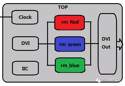
主要功能是,内图产生自测图像,通过DVI接口输出,并同时点亮3个LED灯。其中静态逻辑(Static,灰色部分)负责顶层集成,时钟处理,IIC输出控制接口芯片,产生内部测试图像并输出显示。彩色的部分是可重构逻辑,分别为Red,Blue,和Green三个模块,代表对三个色彩通道分别进行处理的逻辑。
2. ISE流程
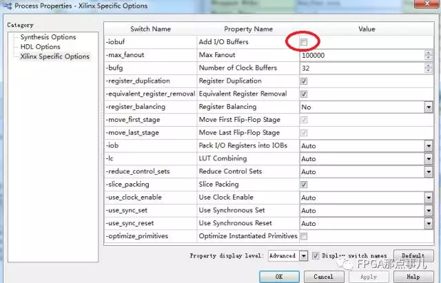
部分可重构开发流程会用到2个工具ISE和Planahead。其中ISE负责把静态逻辑,和各个重构模块,分别独立综合成网标文件,提供给Planahead使用。 综合的时候要尤其注意,静态逻辑Static是可以加管脚约束的,各个重构模块逻辑综合时,要选择不添加IO buffer,如下图所示:
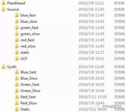
各个模块的ISE工程已经在Synth文件夹下组织好了,可以直接用ISE14.7打开。 3.Planahead流程
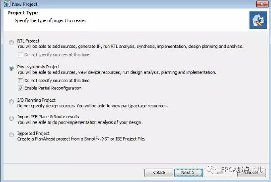
部分可重构的主要工作都在Planahead下完成,大体分成4个步骤: A.建立Planahead工程,导入Static静态网表和约束文件
首先打开Planahead,选择建立新网表工程,确定Enable PartialReconfiguration功能打开。
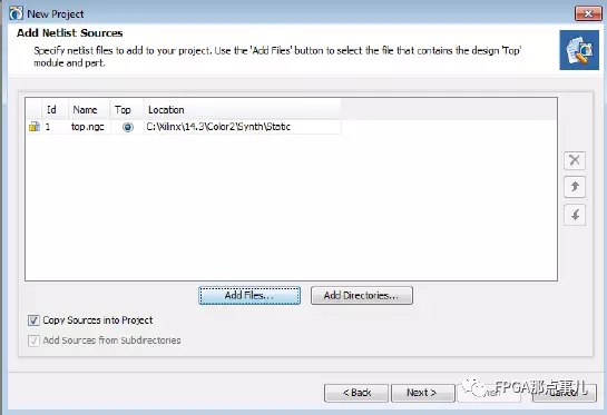
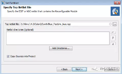
然后依次加入顶层Static网表和ucf约束文件:

B.导入Reconfiguration网表文件并设置Partition
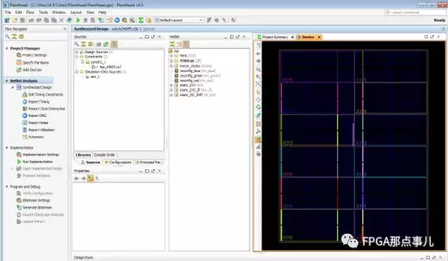
创建完成Planahead工程后,在Flow Manager中,选择Open SynthesizedDesign打开网表设计:
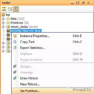
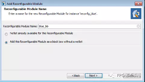
接下来,我们要添加各个可重构的网标文件。选中netlist列表中的某个可重构子Module(此时它是Black Box,什么都没有),右键选择Set Partition:
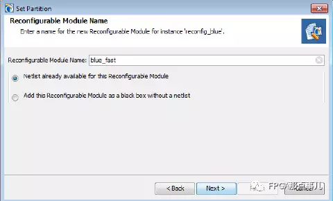
在弹出对话框中,设置比可重构Module某个实现的名字,Next后选择对应网表:
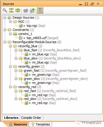
接下来我们还可以在同一个Module下面,继续添加其它不同实现的网表文件,也可以添加Black Box网表(即空网表):

依次把所有的网表都添加完毕,最终,在Source窗口,视图如下:
C.设置Partition
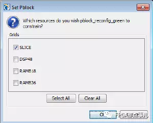
接下来,我们给3个Partition,分别设置其物理区域。使用Set Pblock Size选项,在Device视图中,划定合适的物理区域即可:
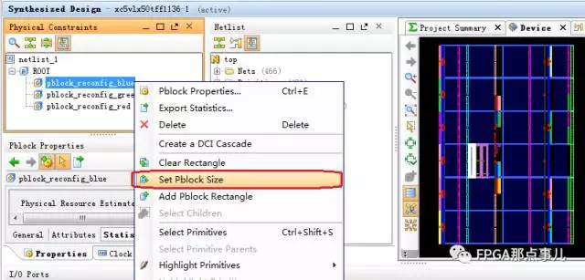
物理区域中会包含多种资源,不需要的我们可以不勾选,这样能减小最终bit文件的大小:
设置完所有的partition后,可以跑一下DRC检查(Tools-> ReportDRC),确保所有的设置都没有问题:
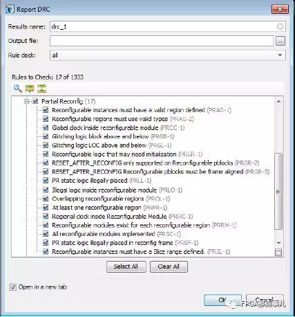
DRC检查结果:

D.创建Implementation Runs
最后我们创建ImplementationRuns,在此处可以创建不同的组合。

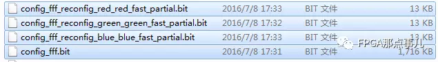
创建完成后,就可以跑Implementation布局布线了,跑完后每个run下都会生成多个bit文件,其中之一是全局的配置bit,另外多个是部分重构的bit文件。 如下示例中,可以看到部分重构的bit文件,相比完整的bit文件,其size很小,因此其加载速度会很快:
 我要赚赏金
我要赚赏金 STM32
STM32 MCU
MCU 通讯及无线技术
 物联网技术
物联网技术 电子DIY
电子DIY 板卡试用
板卡试用 基础知识
基础知识 软件与操作系统
 我爱生活
我爱生活 小e食堂
小e食堂

