
程序1:查询方式::::::::::::::::::
LIN_UART_Syn.rar
#include "mb95200.h"
int ADVoltage=0x01;
void UART_chars(unsigned char cdata);
void UART_init (void)
{
BGR1 = 0x00; // Reloadvalue = 0d51 = 0x33 (500KHz, 9600Baud)
BGR0 = 0x33; // Reloadvalue = 0x33 = 0x00<<8 + 0x33 (500KHz, 9600Baud)
SMR = 0x87; // enable SOT, Reset, synchronous mode
SSR = 0x00; // clear flags, no interrupt
ECCR_SSM = 1; // have ST/STP bit
SCR = 0xc3; // enable transmit, Odd parity
}
char UART_readbyte (void)
{
while (! SSR_RDRF); // wait, until a byte is received
return (RDR_TDR); // return the received byte
}
void delay(unsigned int i)
{
unsigned int m,n;
for(m=0;m<i;m++)
{
for(n=0;n<6000;n++)
{
asm("\tNOP");
}
}
}
void UART_sendbyte (char ch)
{
while (! SSR_TDRE);
RDR_TDR = ch; //transmit data
}
void UARTPut(const char *data,unsigned char len)
{
unsigned char i;
for(i=0; i<len; i++) UART_sendbyte(data[i]);
}
void UART_chars(unsigned char cdata)
{
unsigned char i;
i=cdata>>4;
if(i>=0 && i<=9) UART_sendbyte(i+0x30);
else UART_sendbyte(i+0x37);
i=cdata & 0x0F;
if(i>=0 && i<=9) UART_sendbyte(i+0x30);
else UART_sendbyte(i+0x37);
}
void InitADC(void)
{
ADC2 = 0x81; // 8-bit resolution, enable interrupts
ADC1 = 0x01; // AN0 pin as input, start AD
}
void AD_Sample (void)
{
ADVoltage=ADD_ADDL;
ADC1=0x01;
//ADC2 = 0x81;
}
/******************************************************************************
NAME : main ()
FUNCTION: synchronously transmit a byte or receive a byte
******************************************************************************/
void main (void)
{
//unsigned char rec_data = 0;
DDR0_P00 = 0; //P00 intput
//DDR0_P05 = 1; //P05 output
//DDR0_P06 = 0; //P06 input
DDR0_P03 = 1; //P03 output
DDR0_P04 = 0; //P04 input
AIDRL = 0xfe; //Port input enabled
PDR0_P00 = 0x00;
//PDR0_P05 = 0x01;
UART_init ();
InitIrqLevels(); // initialise Interrupt level register and IRQ vector table
__EI(); // global interrupt enable
//__set_il(3); // set global interrupt mask to allow all IRQ levels
InitADC(); // init AD - converte
while (1)
{
asm("\tNOP");
//UART_sendbyte(0xaa);
delay(10);
UARTPut("ADVal:",7);
//DDR0_P00 = 0;
//delay(1);
AD_Sample();
UART_chars(ADVoltage);
UARTPut("\n",2);
//rec_data = UART_readbyte ();
asm("\tNOP");
asm("\tNOP");
}
}
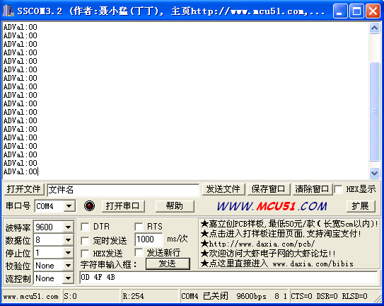 转换的值为:
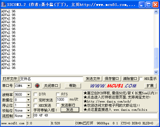

 我要赚赏金
我要赚赏金 STM32
STM32 MCU
MCU 通讯及无线技术
 物联网技术
物联网技术 电子DIY
电子DIY 板卡试用
板卡试用 基础知识
基础知识 软件与操作系统
 我爱生活
我爱生活 小e食堂
小e食堂

