
应网友“只为吸引你”的要求,我帮他写了个Spartan 3E开发板上的ADC的程序,包括程控放大器LTC6912和DAC LTC1407A的接口程序,只做了仿真,还没在板子上跑,请 只为吸引你 和其他感兴趣的网友在板子上调试看看,有什么问题或结果,欢迎反馈。
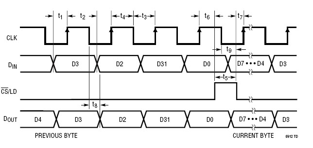
LTC6912时序
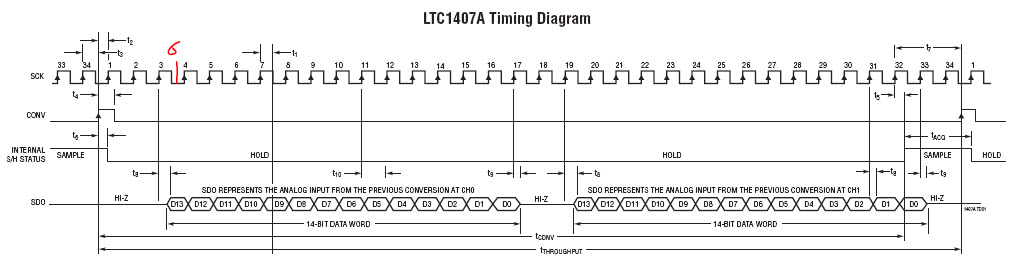
LTC1407A
仿真结果
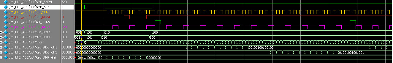
仿真软件为Modelsim 6.5c
接口程序
`timescale 1ns / 1ps
//////////////////////////////////////////////////////////////////////////////////
module LTC_ADC( Clk, Rst,
AMP_nCS, AMP_SHDN, SPI_MOSI,
SPI_SCK,
AD_CONV, SPI_MISO
);
input Clk, Rst;
output wire AMP_SHDN;
output reg AMP_nCS, SPI_MOSI;
output reg SPI_SCK;
output reg AD_CONV;
input SPI_MISO;
//---------------------------------------------------------------------------------------------
assign AMP_SHDN = 1'b0;
parameter AMP_GAIN = 8'h11;
parameter STA_IDLE = 3'b001;
parameter STA_AMP = 3'b010;
parameter STA_ADC = 3'b100;
reg [2:0] Cur_State, Nxt_State;
reg [6:0] Cnter;
reg [13:0] Reg_ADC_CH1, Reg_ADC_CH2;
reg [7:0] Reg_AMP_Gain;
always @( posedge Clk )
begin
if( Rst )
Cur_State <= STA_IDLE;
else
Cur_State <= Nxt_State;
end
always @( Cur_State or Cnter )
begin
case( Cur_State )
STA_IDLE :
begin
if( Cnter == 7'd2 )
Nxt_State = STA_AMP;
else
Nxt_State = STA_IDLE;
end
STA_AMP :
begin
if( Cnter == 7'd16 )
Nxt_State = STA_ADC;
else
Nxt_State = STA_AMP;
end
STA_ADC :
begin
Nxt_State = STA_ADC;
end
default :
begin
Cur_State = STA_IDLE;
end
endcase
end
always @( posedge Clk )
begin
if( Rst )
begin
AMP_nCS <= 1'b1;
SPI_MOSI <= 1'b0;
SPI_SCK <= 1'b1;
AD_CONV <= 1'b0;
Reg_AMP_Gain <= 14'h0000;
Reg_ADC_CH1 <= 14'h0000;
Reg_ADC_CH2 <= 8'h00;
Cnter <= 7'h00;
end
else
begin
case( Cur_State )
STA_IDLE :
begin
if( Cnter < 7'd2 )
begin
AMP_nCS <= 1'b1;
SPI_MOSI <= 1'b0;
SPI_SCK <= 1'b1;
AD_CONV <= 1'b0;
Reg_AMP_Gain <= AMP_GAIN;
Cnter <= Cnter + 1'b1;
end
else
begin
AMP_nCS <= 1'b0;
SPI_MOSI <= 1'b0;
SPI_SCK <= 1'b1;
AD_CONV <= 1'b0;
Reg_AMP_Gain <= AMP_GAIN;
Cnter <= 7'h00;
end
end
STA_AMP :
begin
AMP_nCS <= 1'b0;
if( Cnter < 7'd16 )
begin
Cnter <= Cnter + 1'b1;
if( Cnter[0] == 1'b0 )
begin
SPI_SCK <= 1'b0;
SPI_MOSI <= Reg_AMP_Gain[7];
Reg_AMP_Gain <= { Reg_AMP_Gain[6:0], 1'b0 };
end
else
begin
SPI_SCK <= 1'b1;
end
end
else
begin
Cnter <= 7'd0;
SPI_SCK <= 1'b1;
AMP_nCS <= 1'b1;
AD_CONV <= 1'b0;
end
end
STA_ADC :
begin
if( Cnter==7'd0 )
begin
SPI_SCK <= 1'b0;
AD_CONV <= 1'b1;
Cnter <= Cnter + 1'b1;
end
else if( Cnter==7'd1 )
begin
SPI_SCK <= 1'b1;
Cnter <= Cnter + 1'b1;
end
else if( Cnter <7'd6 )
begin
AD_CONV <= 1'b0;
Cnter <= Cnter + 1'b1;
if( Cnter[0] == 1'b0 )
SPI_SCK <= 1'b0;
else
SPI_SCK <= 1'b1;
end
else if( Cnter <7'd34 )
begin
Cnter <= Cnter + 1'b1;
if( Cnter[0] == 1'b0 )
SPI_SCK <= 1'b0;
else
begin
SPI_SCK <= 1'b1;
Reg_ADC_CH1 <= { Reg_ADC_CH1[12:0], SPI_MISO };
end
end
else if( Cnter <7'd38 )
begin
Cnter <= Cnter + 1'b1;
if( Cnter[0] == 1'b0 )
SPI_SCK <= 1'b0;
else
begin
SPI_SCK <= 1'b1;
end
end
else if( Cnter <7'd66 )
begin
Cnter <= Cnter + 1'b1;
if( Cnter[0] == 1'b0 )
SPI_SCK <= 1'b0;
else
begin
SPI_SCK <= 1'b1;
Reg_ADC_CH2 <= { Reg_ADC_CH2[12:0], SPI_MISO };
end
end
else if( Cnter <7'd68 )
begin
Cnter <= Cnter + 1'b1;
if( Cnter[0] == 1'b0 )
SPI_SCK <= 1'b0;
else
SPI_SCK <= 1'b1;
end
else
begin
Cnter <= 7'd0;
end
end
default :
begin
AMP_nCS <= 1'b1;
SPI_MOSI <= 1'b0;
SPI_SCK <= 1'b1;
AD_CONV <= 1'b0;
Reg_AMP_Gain <= 14'h0000;
Reg_ADC_CH1 <= 14'h0000;
Reg_ADC_CH2 <= 8'h00;
Cnter <= 7'h00;
end
endcase
end
end
// -------------------------- For Simulation ---------------------------------------
initial
begin
Nxt_State = 3'b001;
end
endmodule
Testbench程序--------------------------------------------------------------------------------------------------------
`timescale 1ns / 1ps
//////////////////////////////////////////////////////////////////////////////////
// Company:
// Engineer:
//
// Create Date: 19:53:26 04/01/2011
// Design Name:
// Module Name:
// Project Name:
// Target Devices:
// Tool versions:
// Description:
//
// Dependencies:
//
// Revision:
// Revision 0.01 - File Created
// Additional Comments:
//
//////////////////////////////////////////////////////////////////////////////////
module tb_LTC_ADC;
//module tb_ltc_adc;
reg Clk;
reg Rst;
wire AMP_nCS, AMP_SHDN, SPI_MOSI, SPI_SCK, AD_CONV;
reg SPI_MISO;
LTC_ADC uut(
.Clk( Clk ),
.Rst( Rst ),
.AMP_nCS( AMP_nCS ),
.AMP_SHDN( AMP_SHDN ),
.SPI_MOSI( SPI_MOSI ),
.SPI_SCK( SPI_SCK ),
.AD_CONV( AD_CONV ),
.SPI_MISO( SPI_MISO )
);
always #250 Clk = ~Clk;
initial
begin
// Initialize Inputs
Clk = 0;
Rst = 0;
SPI_MISO = 0;
#2000;
Rst = 1;
#2000;
Rst = 0;
#2000;
while(1)
begin
@( negedge SPI_SCK )
SPI_MISO = 1;
@( negedge SPI_SCK )
SPI_MISO = 0;
@( negedge SPI_SCK )
SPI_MISO = 0;
end
end
endmodule
do文件为
#
# Create work library
#
vlib work
#
# Compile sources
#
vlog "tb_LTC_ADC.v"
vlog "LTC_ADC.v"
#vsim -voptargs="+acc" -t 1ps -lib work.tb_LTC_ADC glbl
vsim -t 1ps -novopt work.tb_LTC_ADC
#
#add wave /tb_LTC_ADC/*
#add wave /tb_LTC_ADC/uut/*
do {wave.do}
# Set the window types
#
view wave
view structure
view signals
#
# Source the user do file
#
#
# Run simulation for this time
#
run 100us
#
# End
#
贴出来的程序我就不排版了,详细的Modelsim工程我已经上传了,可以下载
——回复可见内容——
解压后,用Modelsim打开工程,输入 do run.do 就可以了。
PS. 只为吸引你的程序逻辑上有些乱,我就不帮你检查了,不好意思了。你就参考我的吧。
另外,希望大家以后有什么问题,还是在论坛上大家一起讨论吧,一般不接受站内PM、Email、QQ等提出的问题。

 我要赚赏金
我要赚赏金 STM32
STM32 MCU
MCU 通讯及无线技术
 物联网技术
物联网技术 电子DIY
电子DIY 板卡试用
板卡试用 基础知识
基础知识 软件与操作系统
 我爱生活
我爱生活 小e食堂
小e食堂

