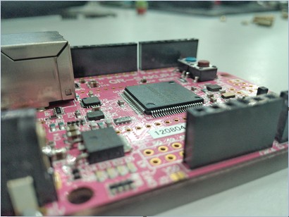
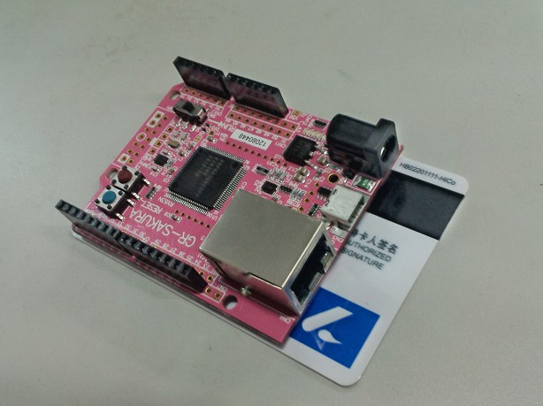
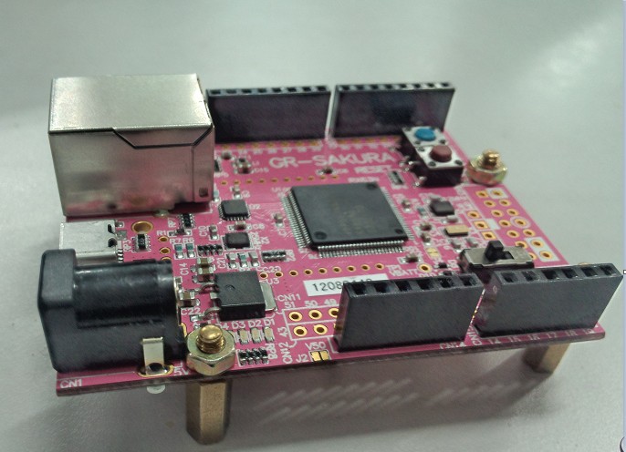
Sakura学习笔记一:数字I/O篇
【语法学习】
【程序结构】
setup()
程序刚启动时,调用setup()函数.用于初始化变量,设置针脚的输出/输入类型,配置串口,引入库文件等等. 每次Arduino上电或重启后,setup函数只运行一次.
loop()
在setup()函数中初始化和定义了变量之后,loop()函数,顾名思义,不停的循环,根据程序中的内容,根据一些反馈,响应改变执行情况。我们就用loop中的代码控制Arduino板。
======================================================================
【数字I/O】
pinMode()
描述
将指定的引脚配置成输出或输入。详情请见digital pins。
语法
pinMode(pin, mode)
参数
pin:要设置模式的引脚
mode:INPUT或OUTPUT
返回:无
digitalWrite()
描述
给一个数字引脚写入HIGH或者LOW。
如果一个引脚已经使用pinMode()配置为OUTPUT模式,其电压将被设置为相应的值,HIGH为5V(3.3V控制板上为3.3V),LOW为0V。
如果引脚配置为INPUT模式,使用digitalWrite()写入HIGH值,将使内部20K上拉电阻(详见数字引脚教程)。写入LOW将会禁用上拉。上拉电阻可以点亮一个LED让其微微亮,如果LED工作,但是亮度很低,可能是因为这个原因引起的。补救的办法是 使用pinMode()函数设置为输出引脚。
语法
digitalWrite(pin, value)
参数
pin: 引脚编号(如1,5,10,A0,A3)
value: HIGH or LOW
返回:无
digitalRead()
描述
读取指定引脚的值,HIGH或LOW。
语法
digitalRead(PIN)
参数
pin:你想读取的引脚号(int)
返回
HIGH 或 LOW
======================================================================
【实验一】数字输出
本实验是对Sakura的数字I/O口的输出操作,LED流水灯。程序官网中已给出:
/*GR-SAKURA Sketch Template Version: V1.02*/
#include <rxduino.h>
#define INTERVAL 500
void setup()
{
pinMode(PIN_LED0,OUTPUT);
pinMode(PIN_LED1,OUTPUT);
pinMode(PIN_LED2,OUTPUT);
pinMode(PIN_LED3,OUTPUT);
}
void loop()
{
digitalWrite(PIN_LED0, 1);
delay(INTERVAL);
digitalWrite(PIN_LED1, 1);
delay(INTERVAL);
digitalWrite(PIN_LED2, 1);
delay(INTERVAL);
digitalWrite(PIN_LED3, 1);
delay(INTERVAL);
digitalWrite(PIN_LED0, 0);
delay(INTERVAL);
digitalWrite(PIN_LED1, 0);
delay(INTERVAL);
digitalWrite(PIN_LED2, 0);
delay(INTERVAL);
digitalWrite(PIN_LED3, 0);
delay(INTERVAL);
}
【实验二】数字输入
本实验是检测Sakura的数字I/O口的输入,并且用板上的LED的亮灭显示输入的值。
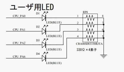
Sakura板LED原理图
由于板上LED是给高电平点亮的,按键板上的按键在松开的时候是连接VCC,这样在没有全按下的时候,LED接高电平,全部点亮。为了方便实验的观察,将读入的按键进行取非操作。具体程序如下:
#include <rxduino.h>
//定义变量存储按键值
int val_0 = 0;
int val_1 = 0;
int val_2 = 0;
int val_3 = 0;
void setup()
{
pinMode(PIN_LED0,OUTPUT); //将4位LED设置为输出
pinMode(PIN_LED1,OUTPUT);
pinMode(PIN_LED2,OUTPUT);
pinMode(PIN_LED3,OUTPUT);
pinMode(0, INPUT); // 将0脚设置为输入
pinMode(1, INPUT); // 将1脚设置为输入
pinMode(2, INPUT); // 将2脚设置为输入
pinMode(3, INPUT); // 将3脚设置为输入
}
void loop()
{
val_0 = digitalRead(0); // 读取按键值
val_1 = digitalRead(1);
val_2 = digitalRead(2);
val_3 = digitalRead(3);
digitalWrite(PIN_LED0, !val_0); //将按键值进行取非操作 并写给LED
digitalWrite(PIN_LED1, !val_1);
digitalWrite(PIN_LED2, !val_2);
digitalWrite(PIN_LED3, !val_3);
}
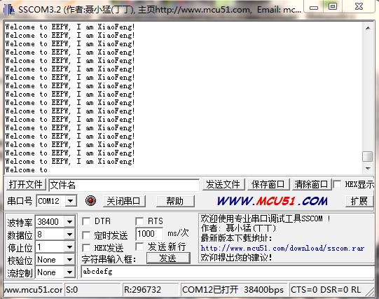
视频:


 我要赚赏金
我要赚赏金 STM32
STM32 MCU
MCU 通讯及无线技术
 物联网技术
物联网技术 电子DIY
电子DIY 板卡试用
板卡试用 基础知识
基础知识 软件与操作系统
 我爱生活
我爱生活 小e食堂
小e食堂

