
嘿嘿,代码是多了点,有点乱
串口控制LED转速
这代码之前改来改去改到弄不出了,害得昨晚白忙活,现在终于被我弄回来了,代码先这样,待改进争取做得更好
密码 12
#include "stm32f10x.h"
#include "stm32_eval.h"
#include "math.h"
#include    "stdio.h"
#define buff_size  16;
char rx_buff[],rx_buff_count=0;
GPIO_InitTypeDef GPIO_InitStructure;


void RCC_Configuration(void)
{
  RCC_DeInit();

  RCC_HSICmd(ENABLE);
  while(RCC_GetFlagStatus(RCC_FLAG_HSIRDY) == RESET);

  RCC_SYSCLKConfig(RCC_SYSCLKSource_HSI);

  RCC_HSEConfig(RCC_HSE_OFF);
  RCC_LSEConfig(RCC_LSE_OFF);
  RCC_PLLConfig(RCC_PLLSource_HSI_Div2,RCC_PLLMul_9); //  72HMz
  RCC_PLLCmd(ENABLE);
  while(RCC_GetFlagStatus(RCC_FLAG_PLLRDY) == RESET);
  RCC_ADCCLKConfig(RCC_PCLK2_Div4);
  RCC_PCLK2Config(RCC_HCLK_Div1);
  RCC_PCLK1Config(RCC_HCLK_Div2);
  RCC_HCLKConfig(RCC_SYSCLK_Div1);
  RCC_SYSCLKConfig(RCC_SYSCLKSource_PLLCLK);
  while(RCC_GetSYSCLKSource() != 0x08);
	RCC_APB2PeriphClockCmd(RCC_APB2Periph_GPIOD|RCC_APB2Periph_AFIO, ENABLE);
 GPIO_PinRemapConfig(GPIO_Remap_SWJ_JTAGDisable,ENABLE);//disable JTAG
  GPIO_InitStructure.GPIO_Pin = GPIO_Pin_2;
  GPIO_InitStructure.GPIO_Speed = GPIO_Speed_50MHz;
  GPIO_InitStructure.GPIO_Mode = GPIO_Mode_Out_PP;
  GPIO_Init(GPIOD, &GPIO_InitStructure);
	GPIO_ResetBits(GPIOD,GPIO_Pin_2);
}

void GPIO_INIT()
{
     RCC_APB2PeriphClockCmd(RCC_APB2Periph_GPIOC, ENABLE);
     GPIO_InitStructure.GPIO_Pin = GPIO_Pin_0|GPIO_Pin_1|GPIO_Pin_2|GPIO_Pin_3|GPIO_Pin_4|GPIO_Pin_5|GPIO_Pin_6|GPIO_Pin_7;
     GPIO_InitStructure.GPIO_Speed = GPIO_Speed_50MHz;
     GPIO_InitStructure.GPIO_Mode = GPIO_Mode_Out_PP;
     GPIO_Init(GPIOC, &GPIO_InitStructure);
	GPIO_SetBits(GPIOC,GPIO_Pin_0|GPIO_Pin_1|GPIO_Pin_2|GPIO_Pin_3|GPIO_Pin_4|GPIO_Pin_5|GPIO_Pin_6|GPIO_Pin_7);
}
void delay_us(u32 n)
{
	u8 j;
	while(n--)
	for(j=0;j<10;j++);
}
void  delay_ms(u32 n)
{
	while(n--)
	delay_us(1000);
}


void USART_int(long BaudRate)
{
  //
//
//
	RCC_APB2PeriphClockCmd(RCC_APB2Periph_GPIOA|RCC_APB2Periph_USART1,ENABLE);
       GPIO_InitStructure.GPIO_Pin = GPIO_Pin_9;
    GPIO_InitStructure.GPIO_Speed = GPIO_Speed_10MHz;
    GPIO_InitStructure.GPIO_Mode = GPIO_Mode_AF_PP;
    GPIO_Init(GPIOA, &GPIO_InitStructure);
    /* PA10 USART1_Rx  */
    GPIO_InitStructure.GPIO_Pin = GPIO_Pin_10;
    GPIO_InitStructure.GPIO_Mode = GPIO_Mode_IN_FLOATING;
    GPIO_Init(GPIOA, &GPIO_InitStructure);
  /* USARTx configured as follow:
        - BaudRate = 115200 baud
        - Word Length = 8 Bits
        - One Stop Bit
        - No parity
        - Hardware flow control disabled (RTS and CTS signals)
        - Receive and transmit enabled
  */
  USART_InitStructure.USART_BaudRate = BaudRate;//??????
  USART_InitStructure.USART_WordLength = USART_WordLength_8b;//???????8bit
  USART_InitStructure.USART_StopBits = USART_StopBits_1;//????1
  USART_InitStructure.USART_Parity = USART_Parity_No;//????
  USART_InitStructure.USART_HardwareFlowControl = USART_HardwareFlowControl_None;//??????none
  USART_InitStructure.USART_Mode = USART_Mode_Rx | USART_Mode_Tx;//??????????
	USART_ClockInitStructure.USART_Clock = USART_Clock_Disable;
    USART_ClockInitStructure.USART_CPOL = USART_CPOL_Low;
    USART_ClockInitStructure.USART_CPHA = USART_CPHA_2Edge;
    USART_ClockInitStructure.USART_LastBit = USART_LastBit_Disable;
    USART_ClockInit(USART1, &USART_ClockInitStructure);
  USART_Init(USART1, &USART_InitStructure);
  USART_Cmd(USART1, ENABLE);
	USART_ITConfig(USART1, USART_IT_RXNE, ENABLE);
 USART_Cmd(USART1, ENABLE);

  /* Configure four bit for preemption priority */
  NVIC_PriorityGroupConfig(NVIC_PriorityGroup_4);
  /* Enable the USART1 Interrupt */
  NVIC_InitStructure.NVIC_IRQChannel = USART1_IRQn; //
  NVIC_InitStructure.NVIC_IRQChannelPreemptionPriority = 15;
  NVIC_InitStructure.NVIC_IRQChannelCmd = ENABLE;
  NVIC_Init(&NVIC_InitStructure);
}

  /*void func(void)
	{
		int i,j;
		GPIO_SetBits(GPIOC,0x00ff);
                    i=0x0010;
          for(j=1;j<=4;j++)
          {
                        i>>=1;
                        GPIO_ResetBits(GPIOC,i);
            delay_ms(60);
                        GPIO_SetBits(GPIOC,i);
          }
                    i=0x0008;
           for(j=1;j<=4;j++)
          {
                        i<<=1;
                        GPIO_ResetBits(GPIOC,i);
                        delay_ms(60);
                        GPIO_SetBits(GPIOC,i);
	}
}*/

void USART_SendStr(char *str)
{
   while((*str)!='\0')
{USART_SendData(USART1,*str++);
while(USART_GetFlagStatus(USART1, USART_FLAG_TXE) == RESET);
}
}

char strcmp(char *S,char *C,char LEN)
{ char count;
  for(count=0;count>=1;
                        GPIO_ResetBits(GPIOC,i);
            delay_ms(60);
                        GPIO_SetBits(GPIOC,i);
          }
                    i=0x0008;
           for(j=1;j<=4;j++)
          {
                        i<<=1;
                        GPIO_ResetBits(GPIOC,i);
                        delay_ms(60);
                        GPIO_SetBits(GPIOC,i);
          }}break;}
     case 8:
         	 flag = strcmp(S,"time=100",8);
         	  if(flag==1)
         	  {while(1){GPIO_SetBits(GPIOC,0x00ff);
                    i=0x0010;
          for(j=1;j<=4;j++)
          {
                        i>>=1;
                        GPIO_ResetBits(GPIOC,i);
            delay_ms(100);
                        GPIO_SetBits(GPIOC,i);
          }
                    i=0x0008;
           for(j=1;j<=4;j++)
          {
                        i<<=1;
                        GPIO_ResetBits(GPIOC,i);
                        delay_ms(100);
                        GPIO_SetBits(GPIOC,i);
          }}break;}

     case 9:
         	 flag = strcmp(S,"time=1000",9);
         	  if(flag==1)
         	  {while(1){ GPIO_SetBits(GPIOC,0x00ff);
                    i=0x0010;
          for(j=1;j<=4;j++)
          {
                        i>>=1;
                        GPIO_ResetBits(GPIOC,i);
            delay_ms(1000);
                        GPIO_SetBits(GPIOC,i);
          }
                    i=0x0008;
           for(j=1;j<=4;j++)
          {
                        i<<=1;
                        GPIO_ResetBits(GPIOC,i);
                        delay_ms(1000);
                        GPIO_SetBits(GPIOC,i);
          }}break;}
   }
 }
}

void input_ASK()
{	char j;
	commcmp(rx_buff,rx_buff_count);
	 rx_buff_count=0;
	  for (j=0;j");
}

int main(void)
{

	RCC_Configuration();
	GPIO_INIT();
  USART_int(9600);
	USART_SendStr("SyStem booting......\r\n");
	USART_SendStr("\n>");
while(1){}
}


/*int main(void)
{

	char str[]="hello,gxnu\r\n";
	unsigned char flag;
	RCC_Configuration();
	GPIO_INIT();
  USART_int(9600);
	GPIO_ResetBits(GPIOC,GPIO_Pin_0|GPIO_Pin_1|GPIO_Pin_2|GPIO_Pin_3|GPIO_Pin_4|GPIO_Pin_5|GPIO_Pin_6|GPIO_Pin_7);
	delay_ms(100);
	GPIO_SetBits(GPIOC,GPIO_Pin_0|GPIO_Pin_1|GPIO_Pin_2|GPIO_Pin_3|GPIO_Pin_4|GPIO_Pin_5|GPIO_Pin_6|GPIO_Pin_7);
	USART_SendStr("SyStem booting......\r\n");
	USART_SendStr("\n>");
	while(1){
}
}*/


void USART1_IRQHandler(void)
{

  while(USART_GetFlagStatus(USART1, USART_FLAG_RXNE) == RESET)
  {
  }
if(USART_ReceiveData(USART1)==0x0d)
{input_ASK();}
else
{
USART_SendData(USART1,USART_ReceiveData(USART1));
rx_buff[rx_buff_count]= USART_ReceiveData(USART1);
	rx_buff_count++;
}
  USART_ClearFlag(USART1, USART_FLAG_RXNE);

}
STM32外部中断
密码:12
#include "stm32f10x.h"
#include "stm32_eval.h"
#include
/** @addtogroup STM32F10x_StdPeriph_Examples
  * @{
  */

/** @addtogroup EXTI_Config
  * @{
  */

/* Private typedef -----------------------------------------------------------*/
/* Private define ------------------------------------------------------------*/
/* Private macro -------------------------------------------------------------*/
/* Private variables ---------------------------------------------------------*/
EXTI_InitTypeDef   EXTI_InitStructure;
GPIO_InitTypeDef   GPIO_InitStructure;
NVIC_InitTypeDef   NVIC_InitStructure;
USART_InitTypeDef USART_InitStructure;
USART_ClockInitTypeDef USART_ClockInitStructure;
/* Private function prototypes -----------------------------------------------*/
void EXTIkeyS1_Config(void);
void EXTIkeyS2_Config(void);
void EXTIkeyS3_Config(void);
void EXTIkeyS4_Config(void);
void RCC_Configuration(void)
{
  RCC_DeInit();

  RCC_HSICmd(ENABLE);
  while(RCC_GetFlagStatus(RCC_FLAG_HSIRDY) == RESET);

  RCC_SYSCLKConfig(RCC_SYSCLKSource_HSI);

  RCC_HSEConfig(RCC_HSE_OFF);
  RCC_LSEConfig(RCC_LSE_OFF);
  RCC_PLLConfig(RCC_PLLSource_HSI_Div2,RCC_PLLMul_9); //  72HMz
  RCC_PLLCmd(ENABLE);
  while(RCC_GetFlagStatus(RCC_FLAG_PLLRDY) == RESET);
  RCC_ADCCLKConfig(RCC_PCLK2_Div4);
  RCC_PCLK2Config(RCC_HCLK_Div1);
  RCC_PCLK1Config(RCC_HCLK_Div2);
  RCC_HCLKConfig(RCC_SYSCLK_Div1);
  RCC_SYSCLKConfig(RCC_SYSCLKSource_PLLCLK);
  while(RCC_GetSYSCLKSource() != 0x08);
	RCC_APB2PeriphClockCmd(RCC_APB2Periph_GPIOD|RCC_APB2Periph_AFIO, ENABLE);
 GPIO_PinRemapConfig(GPIO_Remap_SWJ_JTAGDisable,ENABLE);//disable JTAG
RCC_APB2PeriphClockCmd(RCC_APB2Periph_GPIOD|RCC_APB2Periph_AFIO, ENABLE);
 GPIO_PinRemapConfig(GPIO_Remap_SWJ_JTAGDisable,ENABLE);//disable JTAG
  GPIO_InitStructure.GPIO_Pin = GPIO_Pin_2;
  GPIO_InitStructure.GPIO_Speed = GPIO_Speed_50MHz;
  GPIO_InitStructure.GPIO_Mode = GPIO_Mode_Out_PP;
  GPIO_Init(GPIOD, &GPIO_InitStructure);
	GPIO_ResetBits(GPIOD,GPIO_Pin_2);
	RCC_APB2PeriphClockCmd(RCC_APB2Periph_GPIOC|RCC_APB2Periph_AFIO, ENABLE);
 GPIO_PinRemapConfig(GPIO_Remap_SWJ_JTAGDisable,ENABLE);//disable JTAG
  GPIO_InitStructure.GPIO_Pin = GPIO_Pin_0|GPIO_Pin_1|GPIO_Pin_2|GPIO_Pin_3|GPIO_Pin_4|GPIO_Pin_5|GPIO_Pin_6|GPIO_Pin_7;
  GPIO_InitStructure.GPIO_Speed = GPIO_Speed_50MHz;
  GPIO_InitStructure.GPIO_Mode = GPIO_Mode_Out_PP;
  GPIO_Init(GPIOC, &GPIO_InitStructure);
	GPIO_ResetBits(GPIOC,GPIO_Pin_0|GPIO_Pin_1|GPIO_Pin_2|GPIO_Pin_3|GPIO_Pin_4|GPIO_Pin_5|GPIO_Pin_6|GPIO_Pin_7);
}

void USART_int(long BaudRate)
{
	RCC_APB2PeriphClockCmd(RCC_APB2Periph_GPIOA|RCC_APB2Periph_USART1,ENABLE);
       GPIO_InitStructure.GPIO_Pin = GPIO_Pin_9;
    GPIO_InitStructure.GPIO_Speed = GPIO_Speed_10MHz;
    GPIO_InitStructure.GPIO_Mode = GPIO_Mode_AF_PP;
    GPIO_Init(GPIOA, &GPIO_InitStructure);
    /* PA10 USART1_Rx  */
    GPIO_InitStructure.GPIO_Pin = GPIO_Pin_10;
    GPIO_InitStructure.GPIO_Mode = GPIO_Mode_IN_FLOATING;
    GPIO_Init(GPIOA, &GPIO_InitStructure);
  /* USARTx configured as follow:
        - BaudRate = 115200 baud
        - Word Length = 8 Bits
        - One Stop Bit
        - No parity
        - Hardware flow control disabled (RTS and CTS signals)
        - Receive and transmit enabled
  */
  USART_InitStructure.USART_BaudRate = BaudRate;//??????
  USART_InitStructure.USART_WordLength = USART_WordLength_8b;//???????8bit
  USART_InitStructure.USART_StopBits = USART_StopBits_1;//????1
  USART_InitStructure.USART_Parity = USART_Parity_No;//????
  USART_InitStructure.USART_HardwareFlowControl = USART_HardwareFlowControl_None;//??????none
  USART_InitStructure.USART_Mode = USART_Mode_Rx | USART_Mode_Tx;//??????????
	USART_ClockInitStructure.USART_Clock = USART_Clock_Disable;
    USART_ClockInitStructure.USART_CPOL = USART_CPOL_Low;
    USART_ClockInitStructure.USART_CPHA = USART_CPHA_2Edge;
    USART_ClockInitStructure.USART_LastBit = USART_LastBit_Disable;
    USART_ClockInit(USART1, &USART_ClockInitStructure);
  USART_Init(USART1, &USART_InitStructure);
  USART_Cmd(USART1, ENABLE);
	USART_ITConfig(USART1, USART_IT_RXNE, ENABLE);
 USART_Cmd(USART1, ENABLE);

  /* Configure four bit for preemption priority */
  NVIC_PriorityGroupConfig(NVIC_PriorityGroup_4);
  /* Enable the USART1 Interrupt */
  NVIC_InitStructure.NVIC_IRQChannel = USART1_IRQn; //
  NVIC_InitStructure.NVIC_IRQChannelPreemptionPriority = 15;
  NVIC_InitStructure.NVIC_IRQChannelCmd = ENABLE;
  NVIC_Init(&NVIC_InitStructure);
}

/* Private functions ---------------------------------------------------------*/

/**
  * @brief  Main program.
  * @param  None
  * @retval None
  */
int main(void)
{
	RCC_Configuration();
  EXTIkeyS1_Config();
  EXTIkeyS2_Config();
	EXTIkeyS3_Config();
	EXTIkeyS4_Config();
  USART_int(115200);
	printf("Config done,waiting for interrupt......\r\n");
  while (1) {}
}

/**
  * @brief  Configure PA.00 in interrupt mode
  * @param  None
  * @retval None
  */

void NVIC_InitS1(void)
{
	NVIC_InitStructure.NVIC_IRQChannel = EXTI9_5_IRQn;
  NVIC_InitStructure.NVIC_IRQChannelPreemptionPriority = 0x0F;
  NVIC_InitStructure.NVIC_IRQChannelSubPriority = 0x0F;
  NVIC_InitStructure.NVIC_IRQChannelCmd = ENABLE;
  NVIC_Init(&NVIC_InitStructure);
}
void NVIC_InitS2(void)
{
	NVIC_InitStructure.NVIC_IRQChannel = EXTI15_10_IRQn;
  NVIC_InitStructure.NVIC_IRQChannelPreemptionPriority = 0x0F;
  NVIC_InitStructure.NVIC_IRQChannelSubPriority = 0x0F;
  NVIC_InitStructure.NVIC_IRQChannelCmd = ENABLE;
  NVIC_Init(&NVIC_InitStructure);
}

void EXTIkeyS1_Config(void)
{
  RCC_APB2PeriphClockCmd(RCC_APB2Periph_GPIOC, ENABLE);
  GPIO_InitStructure.GPIO_Pin = GPIO_Pin_8;
  GPIO_InitStructure.GPIO_Mode = GPIO_Mode_IN_FLOATING;
  GPIO_Init(GPIOA, &GPIO_InitStructure);
  RCC_APB2PeriphClockCmd(RCC_APB2Periph_AFIO, ENABLE);
  GPIO_EXTILineConfig(GPIO_PortSourceGPIOC, GPIO_PinSource8);
  EXTI_InitStructure.EXTI_Line = EXTI_Line8;
  EXTI_InitStructure.EXTI_Mode = EXTI_Mode_Interrupt;
  EXTI_InitStructure.EXTI_Trigger = EXTI_Trigger_Falling;
  EXTI_InitStructure.EXTI_LineCmd = ENABLE;
  EXTI_Init(&EXTI_InitStructure);
  NVIC_InitS1();
}


void EXTIkeyS2_Config(void)
{
  RCC_APB2PeriphClockCmd(RCC_APB2Periph_GPIOC, ENABLE);
  GPIO_InitStructure.GPIO_Pin = GPIO_Pin_9;
  GPIO_InitStructure.GPIO_Mode = GPIO_Mode_IN_FLOATING;
  GPIO_Init(GPIOC, &GPIO_InitStructure);
  RCC_APB2PeriphClockCmd(RCC_APB2Periph_AFIO, ENABLE);
  GPIO_EXTILineConfig(GPIO_PortSourceGPIOC, GPIO_PinSource9);
  EXTI_InitStructure.EXTI_Line = EXTI_Line9;
  EXTI_InitStructure.EXTI_Mode = EXTI_Mode_Interrupt;
  EXTI_InitStructure.EXTI_Trigger = EXTI_Trigger_Falling;
  EXTI_InitStructure.EXTI_LineCmd = ENABLE;
  EXTI_Init(&EXTI_InitStructure);
  NVIC_InitS1();
}

void EXTIkeyS3_Config(void)
{
  RCC_APB2PeriphClockCmd(RCC_APB2Periph_GPIOC, ENABLE);
  GPIO_InitStructure.GPIO_Pin = GPIO_Pin_10;
  GPIO_InitStructure.GPIO_Mode = GPIO_Mode_IN_FLOATING;
  GPIO_Init(GPIOA, &GPIO_InitStructure);
  RCC_APB2PeriphClockCmd(RCC_APB2Periph_AFIO, ENABLE);
  GPIO_EXTILineConfig(GPIO_PortSourceGPIOC, GPIO_PinSource10);
  EXTI_InitStructure.EXTI_Line = EXTI_Line10;
  EXTI_InitStructure.EXTI_Mode = EXTI_Mode_Interrupt;
  EXTI_InitStructure.EXTI_Trigger = EXTI_Trigger_Falling;
  EXTI_InitStructure.EXTI_LineCmd = ENABLE;
  EXTI_Init(&EXTI_InitStructure);
  NVIC_InitS2();
}

void EXTIkeyS4_Config(void)
{
  RCC_APB2PeriphClockCmd(RCC_APB2Periph_GPIOC, ENABLE);
  GPIO_InitStructure.GPIO_Pin = GPIO_Pin_11;
  GPIO_InitStructure.GPIO_Mode = GPIO_Mode_IN_FLOATING;
  GPIO_Init(GPIOC, &GPIO_InitStructure);
  RCC_APB2PeriphClockCmd(RCC_APB2Periph_AFIO, ENABLE);
  GPIO_EXTILineConfig(GPIO_PortSourceGPIOC, GPIO_PinSource11);
  EXTI_InitStructure.EXTI_Line = EXTI_Line11;
  EXTI_InitStructure.EXTI_Mode = EXTI_Mode_Interrupt;
  EXTI_InitStructure.EXTI_Trigger = EXTI_Trigger_Falling;
  EXTI_InitStructure.EXTI_LineCmd = ENABLE;
  EXTI_Init(&EXTI_InitStructure);
  NVIC_InitS2();
}

/******************************************************************************/
/*            STM32F10x Peripherals Interrupt Handlers                        */
/******************************************************************************/

/**
  * @brief  This function handles External lines 9 to 5 interrupt request.
  * @param  None
  * @retval None
  */
void EXTI9_5_IRQHandler(void)
{
  if(EXTI_GetITStatus(EXTI_Line8) != RESET)
  {
    /* Toggle LED2 */
     GPIO_SetBits(GPIOC,GPIO_Pin_4|GPIO_Pin_5|GPIO_Pin_6|GPIO_Pin_7);
printf("S1 interrupt ......\r\n");
    /* Clear the  EXTI line 9 pending bit */
    EXTI_ClearITPendingBit(EXTI_Line8);
  }
	if(EXTI_GetITStatus(EXTI_Line9) != RESET)
  {
    /* Toggle LED1 */
     GPIO_SetBits(GPIOC,GPIO_Pin_0|GPIO_Pin_1|GPIO_Pin_2|GPIO_Pin_3);
printf("S2 interrupt ......\r\n");
    /* Clear the  EXTI line 0 pending bit */
    EXTI_ClearITPendingBit(EXTI_Line9);
  }
}
void EXTI15_10_IRQHandler(void)
{
  if(EXTI_GetITStatus(EXTI_Line10) != RESET)
  {
    /* Toggle LED2 */
     GPIO_ResetBits(GPIOC,GPIO_Pin_4|GPIO_Pin_5|GPIO_Pin_6|GPIO_Pin_7);
printf("S3 interrupt ......\r\n");
    /* Clear the  EXTI line 9 pending bit */
    EXTI_ClearITPendingBit(EXTI_Line10);
  }
	if(EXTI_GetITStatus(EXTI_Line11) != RESET)
  {
    /* Toggle LED1 */
     GPIO_ResetBits(GPIOC,GPIO_Pin_0|GPIO_Pin_1|GPIO_Pin_2|GPIO_Pin_3);
printf("S4 interrupt ......\r\n");
    /* Clear the  EXTI line 0 pending bit */
    EXTI_ClearITPendingBit(EXTI_Line11);
  }
}


#ifdef  USE_FULL_ASSERT

/**
  * @brief  Reports the name of the source file and the source line number
  *         where the assert_param error has occurred.
  * @param  file: pointer to the source file name
  * @param  line: assert_param error line source number
  * @retval None
  */
void assert_failed(uint8_t* file, uint32_t line)
{
  /* User can add his own implementation to report the file name and line number,
     ex: printf("Wrong parameters value: file %s on line %d\r\n", file, line) */

  /* Infinite loop */
  while (1)
  {
  }
}

#endif

/**
  * @}
  */

/**
  * @}
  */

#ifdef __GNUC__
  /* With GCC/RAISONANCE, small printf (option LD Linker->Libraries->Small printf
     set to 'Yes') calls __io_putchar() */
  #define PUTCHAR_PROTOTYPE int __io_putchar(int ch)
#else
  #define PUTCHAR_PROTOTYPE int fputc(int ch, FILE *f)
#endif /* __GNUC__ */


/**
  * @brief  Retargets the C library printf function to the USART.
  * @param  None
  * @retval None
  */
PUTCHAR_PROTOTYPE
{
  /* Place your implementation of fputc here */
  /* e.g. write a character to the USART */
  USART_SendData(EVAL_COM1, (uint8_t) ch);

  /* Loop until the end of transmission */
  while (USART_GetFlagStatus(EVAL_COM1, USART_FLAG_TC) == RESET)
  {}

  return ch;
}

#ifdef  USE_FULL_ASSERT

/**
  * @brief  Reports the name of the source file and the source line number
  *         where the assert_param error has occurred.
  * @param  file: pointer to the source file name
  * @param  line: assert_param error line source number
  * @retval None
  */
void assert_failed(uint8_t* file, uint32_t line)
{
  /* User can add his own implementation to report the file name and line number,
     ex: printf("Wrong parameters value: file %s on line %d\r\n", file, line) */

  /* Infinite loop */
  while (1)
  {
  }
}

#endif

/******************* (C) COPYRIGHT 2011 STMicroelectronics *****END OF FILE****/
TIM7没反应,等我学会I2C2怎么用先
密码:12
/* Includes ------------------------------------------------------------------*/
#include "stm32f10x.h"
#include "stm32_eval.h"
#include
/** @addtogroup STM32F10x_StdPeriph_Examples
  * @{
  */

/** @addtogroup EXTI_Config
  * @{
  */

/* Private typedef -----------------------------------------------------------*/
/* Private define ------------------------------------------------------------*/
/* Private macro -------------------------------------------------------------*/
/* Private variables ---------------------------------------------------------*/
EXTI_InitTypeDef   EXTI_InitStructure;
GPIO_InitTypeDef   GPIO_InitStructure;
NVIC_InitTypeDef   NVIC_InitStructure;
USART_InitTypeDef USART_InitStructure;
USART_ClockInitTypeDef USART_ClockInitStructure;
TIM_TimeBaseInitTypeDef  TIM_TimeBaseStructure;
TIM_OCInitTypeDef  TIM_OCInitStructure;
long flag,temp,num;
void RCC_Configuration(void)
{/*
  RCC_DeInit();

  RCC_HSICmd(ENABLE);
  while(RCC_GetFlagStatus(RCC_FLAG_HSIRDY) == RESET);

  RCC_SYSCLKConfig(RCC_SYSCLKSource_HSI);

  RCC_HSEConfig(RCC_HSE_OFF);
  RCC_LSEConfig(RCC_LSE_OFF);
  RCC_PLLConfig(RCC_PLLSource_HSI_Div2,RCC_PLLMul_9); //  72HMz
  RCC_PLLCmd(ENABLE);
  while(RCC_GetFlagStatus(RCC_FLAG_PLLRDY) == RESET);
  RCC_ADCCLKConfig(RCC_PCLK2_Div4);
  RCC_PCLK2Config(RCC_HCLK_Div1);
  RCC_PCLK1Config(RCC_HCLK_Div2);
  RCC_HCLKConfig(RCC_SYSCLK_Div1);
  RCC_SYSCLKConfig(RCC_SYSCLKSource_PLLCLK);
  while(RCC_GetSYSCLKSource() != 0x08);
*/
    SystemInit();
    RCC_APB2PeriphClockCmd(RCC_APB2Periph_GPIOD|RCC_APB2Periph_AFIO, ENABLE);
  GPIO_PinRemapConfig(GPIO_Remap_SWJ_JTAGDisable,ENABLE);//disable JTAG
   RCC_APB2PeriphClockCmd(RCC_APB2Periph_GPIOD|RCC_APB2Periph_AFIO, ENABLE);
   GPIO_PinRemapConfig(GPIO_Remap_SWJ_JTAGDisable,ENABLE);//disable JTAG
  GPIO_InitStructure.GPIO_Pin = GPIO_Pin_2;
  GPIO_InitStructure.GPIO_Speed = GPIO_Speed_50MHz;
  GPIO_InitStructure.GPIO_Mode = GPIO_Mode_Out_PP;
  GPIO_Init(GPIOD, &GPIO_InitStructure);
    GPIO_ResetBits(GPIOD,GPIO_Pin_2);
    RCC_APB2PeriphClockCmd(RCC_APB2Periph_GPIOC|RCC_APB2Periph_AFIO, ENABLE);
  GPIO_PinRemapConfig(GPIO_Remap_SWJ_JTAGDisable,ENABLE);//disable JTAG
  GPIO_InitStructure.GPIO_Pin = GPIO_Pin_0|GPIO_Pin_1|GPIO_Pin_2|GPIO_Pin_3|GPIO_Pin_4|GPIO_Pin_5|GPIO_Pin_6|GPIO_Pin_7;
  GPIO_InitStructure.GPIO_Speed = GPIO_Speed_50MHz;
  GPIO_InitStructure.GPIO_Mode = GPIO_Mode_Out_PP;
  GPIO_Init(GPIOC, &GPIO_InitStructure);
    GPIO_SetBits(GPIOC,GPIO_Pin_0|GPIO_Pin_1|GPIO_Pin_2|GPIO_Pin_3|GPIO_Pin_4|GPIO_Pin_5|GPIO_Pin_6|GPIO_Pin_7);
    RCC_APB1PeriphClockCmd(RCC_APB1Periph_TIM2, ENABLE);
    RCC_APB1PeriphClockCmd(RCC_APB1Periph_TIM3, ENABLE);
    RCC_APB1PeriphClockCmd(RCC_APB1Periph_TIM7, ENABLE);


}


void USART_int(long BaudRate)
{
    RCC_APB2PeriphClockCmd(RCC_APB2Periph_GPIOA|RCC_APB2Periph_USART1,ENABLE);
       GPIO_InitStructure.GPIO_Pin = GPIO_Pin_9;
    GPIO_InitStructure.GPIO_Speed = GPIO_Speed_10MHz;
    GPIO_InitStructure.GPIO_Mode = GPIO_Mode_AF_PP;
    GPIO_Init(GPIOA, &GPIO_InitStructure);
    /* PA10 USART1_Rx  */
    GPIO_InitStructure.GPIO_Pin = GPIO_Pin_10;
    GPIO_InitStructure.GPIO_Mode = GPIO_Mode_IN_FLOATING;
    GPIO_Init(GPIOA, &GPIO_InitStructure);
  /* USARTx configured as follow:
        - BaudRate = 115200 baud
        - Word Length = 8 Bits
        - One Stop Bit
        - No parity
        - Hardware flow control disabled (RTS and CTS signals)
        - Receive and transmit enabled
  */
  USART_InitStructure.USART_BaudRate = BaudRate;//??????
  USART_InitStructure.USART_WordLength = USART_WordLength_8b;//???????8bit
  USART_InitStructure.USART_StopBits = USART_StopBits_1;//????1
  USART_InitStructure.USART_Parity = USART_Parity_No;//????
  USART_InitStructure.USART_HardwareFlowControl = USART_HardwareFlowControl_None;//??????none
  USART_InitStructure.USART_Mode = USART_Mode_Rx | USART_Mode_Tx;//??????????
    USART_ClockInitStructure.USART_Clock = USART_Clock_Disable;
    USART_ClockInitStructure.USART_CPOL = USART_CPOL_Low;
    USART_ClockInitStructure.USART_CPHA = USART_CPHA_2Edge;
    USART_ClockInitStructure.USART_LastBit = USART_LastBit_Disable;
    USART_ClockInit(USART1, &USART_ClockInitStructure);
  USART_Init(USART1, &USART_InitStructure);
  USART_Cmd(USART1, ENABLE);
    USART_ITConfig(USART1, USART_IT_RXNE, ENABLE);
 USART_Cmd(USART1, ENABLE);
}

void NVIC_Configuration(void)
{
  NVIC_InitTypeDef NVIC_InitStructure;

  /* Enable the TIM2 global Interrupt */
  NVIC_InitStructure.NVIC_IRQChannel = TIM2_IRQn;
  NVIC_InitStructure.NVIC_IRQChannelPreemptionPriority = 0;
  NVIC_InitStructure.NVIC_IRQChannelSubPriority = 1;
  NVIC_InitStructure.NVIC_IRQChannelCmd = ENABLE;
  NVIC_Init(&NVIC_InitStructure);

  NVIC_InitStructure.NVIC_IRQChannel = TIM3_IRQn;
  NVIC_InitStructure.NVIC_IRQChannelPreemptionPriority = 0;
  NVIC_InitStructure.NVIC_IRQChannelSubPriority = 1;
  NVIC_InitStructure.NVIC_IRQChannelCmd = ENABLE;
  NVIC_Init(&NVIC_InitStructure);

  NVIC_InitStructure.NVIC_IRQChannel = TIM7_IRQn;
  NVIC_InitStructure.NVIC_IRQChannelPreemptionPriority = 0;
  NVIC_InitStructure.NVIC_IRQChannelSubPriority = 1;
  NVIC_InitStructure.NVIC_IRQChannelCmd = ENABLE;
  NVIC_Init(&NVIC_InitStructure);

}

/* Private functions ---------------------------------------------------------*/

/**
  * @brief  Main program.
  * @param  None
  * @retval None
  */


int main(void)
{
  /*!< At this stage the microcontroller clock setting is already configured,
       this is done through SystemInit() function which is called from startup
       file (startup_stm32f10x_xx.s) before to branch to application main.
       To reconfigure the default setting of SystemInit() function, refer to
       system_stm32f10x.c file
     */

  /* System Clocks Configuration */
  RCC_Configuration();

NVIC_Configuration();
USART_int(115200);
    printf(" config done...\r\n");

	    /* Time base configuration */
  TIM_TimeBaseStructure.TIM_Period = 24000;
  TIM_TimeBaseStructure.TIM_Prescaler = 0;
  TIM_TimeBaseStructure.TIM_ClockDivision = 0;
  TIM_TimeBaseStructure.TIM_CounterMode = TIM_CounterMode_Up;


  TIM_TimeBaseInit(TIM2, &TIM_TimeBaseStructure);
  TIM_ITConfig(TIM2,TIM_IT_Update,ENABLE );


  TIM_TimeBaseInit(TIM3, &TIM_TimeBaseStructure);
  TIM_ITConfig(TIM3,TIM_IT_Update,ENABLE );

  TIM_TimeBaseInit(TIM7, &TIM_TimeBaseStructure);
  TIM_ITConfig(TIM7,TIM_IT_Update,ENABLE );


  /* TIM2 enable counter */
     TIM_Cmd(TIM2, ENABLE);
     TIM_Cmd(TIM3, ENABLE);
     TIM_Cmd(TIM7, ENABLE);

  while (1){

        if(flag == 2000)
        {  printf("TIM2 interrupt......\r\n");
           flag = 0;
           GPIO_SetBits(GPIOC,GPIO_Pin_0);
           GPIO_ResetBits(GPIOC,GPIO_Pin_1);
        }

        if(temp == 3000)
        {  printf("TIM3 interrupt......\r\n");
           temp = 0;
           GPIO_SetBits(GPIOC,GPIO_Pin_1);
           GPIO_ResetBits(GPIOC,GPIO_Pin_0);
        }
       		    if(num == 1000)
        { printf("TIM7 interrupt......\r\n");
          num = 0;
          GPIO_SetBits(GPIOC,GPIO_Pin_2);
					GPIO_ResetBits(GPIOC,GPIO_Pin_2);
        }
}
}
void TIM2_IRQHandler(void)
{
if (TIM_GetITStatus(TIM2, TIM_IT_Update) != RESET)
  {
    TIM_ClearITPendingBit(TIM2, TIM_IT_Update );
    flag++;
  }
}
void TIM3_IRQHandler(void)
{
if (TIM_GetITStatus(TIM3, TIM_IT_Update) != RESET)
  {
    TIM_ClearITPendingBit(TIM3, TIM_IT_Update );
    temp++;
  }
}

void TIM7_IRQHandler(void)
{
if (TIM_GetITStatus(TIM7, TIM_IT_Update) != RESET)
  {
    TIM_ClearITPendingBit(TIM7, TIM_IT_Update );
    num++;
  }
}


#ifdef  USE_FULL_ASSERT

/**
  * @brief  Reports the name of the source file and the source line number
  *         where the assert_param error has occurred.
  * @param  file: pointer to the source file name
  * @param  line: assert_param error line source number
  * @retval None
  */
void assert_failed(uint8_t* file, uint32_t line)
{
  /* User can add his own implementation to report the file name and line number,
     ex: printf("Wrong parameters value: file %s on line %d\r\n", file, line) */

  /* Infinite loop */
  while (1)
  {
  }
}

#endif

/**
  * @}
  */

/**
  * @}
  */

#ifdef __GNUC__
  /* With GCC/RAISONANCE, small printf (option LD Linker->Libraries->Small printf
     set to 'Yes') calls __io_putchar() */
  #define PUTCHAR_PROTOTYPE int __io_putchar(int ch)
#else
  #define PUTCHAR_PROTOTYPE int fputc(int ch, FILE *f)
#endif /* __GNUC__ */


/**
  * @brief  Retargets the C library printf function to the USART.
  * @param  None
  * @retval None
  */
PUTCHAR_PROTOTYPE
{
  /* Place your implementation of fputc here */
  /* e.g. write a character to the USART */
  USART_SendData(EVAL_COM1, (uint8_t) ch);

  /* Loop until the end of transmission */
  while (USART_GetFlagStatus(EVAL_COM1, USART_FLAG_TC) == RESET)
  {}

  return ch;
}

#ifdef  USE_FULL_ASSERT

/**
  * @brief  Reports the name of the source file and the source line number
  *         where the assert_param error has occurred.
  * @param  file: pointer to the source file name
  * @param  line: assert_param error line source number
  * @retval None
  */
void assert_failed(uint8_t* file, uint32_t line)
{
  /* User can add his own implementation to report the file name and line number,
     ex: printf("Wrong parameters value: file %s on line %d\r\n", file, line) */

  /* Infinite loop */
  while (1)
  {
  }
}

#endif

/******************* (C) COPYRIGHT 2011 STMicroelectronics *****END OF FILE****/
PWM-RBG 八色
三种颜色都亮的话看不出太大变化
密码:12
/**
******************************************************************************
* @file EXTI/EXTI_Config/main.c
* @author MCD Application Team
* @version V3.5.0
* @date 08-April-2011
* @brief Main program body
******************************************************************************
* @attention
*
* THE PRESENT FIRMWARE WHICH IS FOR GUIDANCE ONLY AIMS AT PROVIDING CUSTOMERS
* WITH CODING INFORMATION REGARDING THEIR PRODUCTS IN ORDER FOR THEM TO SAVE
* TIME. AS A RESULT, STMICROELECTRONICS SHALL NOT BE HELD LIABLE FOR ANY
* DIRECT, INDIRECT OR CONSEQUENTIAL DAMAGES WITH RESPECT TO ANY CLAIMS ARISING
* FROM THE CONTENT OF SUCH FIRMWARE AND/OR THE USE MADE BY CUSTOMERS OF THE
* CODING INFORMATION CONTAINED HEREIN IN CONNECTION WITH THEIR PRODUCTS.
*
* <h2><center>© COPYRIGHT 2011 STMicroelectronics</center></h2>
******************************************************************************
*/
/* Includes ------------------------------------------------------------------*/
#include "stm32f10x.h"
#include "stm32_eval.h"
#include <stdio.h>
#define VREF 3.3
/** @addtogroup STM32F10x_StdPeriph_Examples
* @{
*/
/** @addtogroup EXTI_Config
* @{
*/
/* Private typedef -----------------------------------------------------------*/
/* Private define ------------------------------------------------------------*/
/* Private macro -------------------------------------------------------------*/
/* Private variables ---------------------------------------------------------*/
GPIO_InitTypeDef GPIO_InitStructure;
USART_InitTypeDef USART_InitStructure;
USART_ClockInitTypeDef USART_ClockInitStructure;
void RCC_Configuration(void)
{/*
RCC_DeInit();
RCC_HSICmd(ENABLE);
while(RCC_GetFlagStatus(RCC_FLAG_HSIRDY) == RESET);
RCC_SYSCLKConfig(RCC_SYSCLKSource_HSI);
RCC_HSEConfig(RCC_HSE_OFF);
RCC_LSEConfig(RCC_LSE_OFF);
RCC_PLLConfig(RCC_PLLSource_HSI_Div2,RCC_PLLMul_9); // 72HMz
RCC_PLLCmd(ENABLE);
while(RCC_GetFlagStatus(RCC_FLAG_PLLRDY) == RESET);
RCC_ADCCLKConfig(RCC_PCLK2_Div4);
RCC_PCLK2Config(RCC_HCLK_Div1);
RCC_PCLK1Config(RCC_HCLK_Div2);
RCC_HCLKConfig(RCC_SYSCLK_Div1);
RCC_SYSCLKConfig(RCC_SYSCLKSource_PLLCLK);
while(RCC_GetSYSCLKSource() != 0x08);
*/
SystemInit();
RCC_APB2PeriphClockCmd(RCC_APB2Periph_GPIOD|RCC_APB2Periph_AFIO, ENABLE);
GPIO_PinRemapConfig(GPIO_Remap_SWJ_JTAGDisable,ENABLE);//disable JTAG
RCC_APB2PeriphClockCmd(RCC_APB2Periph_GPIOD|RCC_APB2Periph_AFIO, ENABLE);
GPIO_PinRemapConfig(GPIO_Remap_SWJ_JTAGDisable,ENABLE);//disable JTAG
GPIO_InitStructure.GPIO_Pin = GPIO_Pin_2;
GPIO_InitStructure.GPIO_Speed = GPIO_Speed_50MHz;
GPIO_InitStructure.GPIO_Mode = GPIO_Mode_Out_PP;
GPIO_Init(GPIOD, &GPIO_InitStructure);
GPIO_ResetBits(GPIOD,GPIO_Pin_2);
RCC_APB2PeriphClockCmd(RCC_APB2Periph_GPIOC|RCC_APB2Periph_AFIO, ENABLE);
GPIO_PinRemapConfig(GPIO_Remap_SWJ_JTAGDisable,ENABLE);//disable JTAG
GPIO_InitStructure.GPIO_Pin = GPIO_Pin_0|GPIO_Pin_1|GPIO_Pin_2|GPIO_Pin_3|GPIO_Pin_4|GPIO_Pin_5|GPIO_Pin_6|GPIO_Pin_7;
GPIO_InitStructure.GPIO_Speed = GPIO_Speed_50MHz;
GPIO_InitStructure.GPIO_Mode = GPIO_Mode_Out_PP;
GPIO_Init(GPIOC, &GPIO_InitStructure);
GPIO_SetBits(GPIOC,GPIO_Pin_0|GPIO_Pin_1|GPIO_Pin_2|GPIO_Pin_3|GPIO_Pin_4|GPIO_Pin_5|GPIO_Pin_6|GPIO_Pin_7);
RCC_APB1PeriphClockCmd(RCC_APB1Periph_TIM2, ENABLE);
}
void USART_int(long BaudRate)
{
RCC_APB2PeriphClockCmd(RCC_APB2Periph_GPIOA|RCC_APB2Periph_USART1,ENABLE);
GPIO_InitStructure.GPIO_Pin = GPIO_Pin_9;
GPIO_InitStructure.GPIO_Speed = GPIO_Speed_50MHz;
GPIO_InitStructure.GPIO_Mode = GPIO_Mode_AF_PP;
GPIO_Init(GPIOA, &GPIO_InitStructure);
/* PA10 USART1_Rx */
GPIO_InitStructure.GPIO_Pin = GPIO_Pin_10;
GPIO_InitStructure.GPIO_Mode = GPIO_Mode_IN_FLOATING;
GPIO_Init(GPIOA, &GPIO_InitStructure);
/* USARTx configured as follow:
- BaudRate = 115200 baud
- Word Length = 8 Bits
- One Stop Bit
- No parity
- Hardware flow control disabled (RTS and CTS signals)
- Receive and transmit enabled
*/
USART_InitStructure.USART_BaudRate = BaudRate;//??????
USART_InitStructure.USART_WordLength = USART_WordLength_8b;//???????8bit
USART_InitStructure.USART_StopBits = USART_StopBits_1;//????1
USART_InitStructure.USART_Parity = USART_Parity_No;//????
USART_InitStructure.USART_HardwareFlowControl = USART_HardwareFlowControl_None;//??????none
USART_InitStructure.USART_Mode = USART_Mode_Rx | USART_Mode_Tx;//??????????
USART_ClockInitStructure.USART_Clock = USART_Clock_Disable;
USART_ClockInitStructure.USART_CPOL = USART_CPOL_Low;
USART_ClockInitStructure.USART_CPHA = USART_CPHA_2Edge;
USART_ClockInitStructure.USART_LastBit = USART_LastBit_Disable;
USART_ClockInit(USART1, &USART_ClockInitStructure);
USART_Init(USART1, &USART_InitStructure);
USART_Cmd(USART1, ENABLE);
USART_ITConfig(USART1, USART_IT_RXNE, ENABLE);
USART_Cmd(USART1, ENABLE);
}
void PWM_Config()
{uint16_t PrescalerValue = 0;
TIM_TimeBaseInitTypeDef TIM_TimeBaseStructure;
TIM_OCInitTypeDef TIM_OCInitStructure;
/* TIM2 clock enable */
RCC_APB1PeriphClockCmd(RCC_APB1Periph_TIM2, ENABLE);
/* GPIOA enable */
RCC_APB2PeriphClockCmd(RCC_APB2Periph_AFIO , ENABLE);
GPIO_InitStructure.GPIO_Pin = GPIO_Pin_1|GPIO_Pin_2|GPIO_Pin_3;
GPIO_InitStructure.GPIO_Mode = GPIO_Mode_AF_PP;
GPIO_InitStructure.GPIO_Speed = GPIO_Speed_50MHz;
GPIO_Init(GPIOA, &GPIO_InitStructure);
TIM_Cmd(TIM2, ENABLE);
/* Compute the prescaler value */
PrescalerValue = (uint16_t) (SystemCoreClock / 24000000) - 1;
/* Time base configuration */
TIM_TimeBaseStructure.TIM_Period = 0x07FF;
TIM_TimeBaseStructure.TIM_Prescaler = PrescalerValue;
TIM_TimeBaseStructure.TIM_ClockDivision = 0;
TIM_TimeBaseStructure.TIM_CounterMode = TIM_CounterMode_Up;
TIM_TimeBaseInit(TIM2, &TIM_TimeBaseStructure);
TIM_OCInitStructure.TIM_OCMode = TIM_OCMode_PWM1;
TIM_OCInitStructure.TIM_OCPolarity = TIM_OCPolarity_High;
/* PWM1 Mode configuration: Channel2 */
TIM_OCInitStructure.TIM_OutputState = TIM_OutputState_Enable;
TIM_OCInitStructure.TIM_Pulse = 0xFFFF;
TIM_OC2Init(TIM2, &TIM_OCInitStructure);
/* PWM1 Mode configuration: Channel3 */
TIM_OCInitStructure.TIM_OutputState = TIM_OutputState_Enable;
TIM_OCInitStructure.TIM_Pulse = 0xFFFF;
TIM_OC3Init(TIM2, &TIM_OCInitStructure);
/* PWM1 Mode configuration: Channel4 */
TIM_OCInitStructure.TIM_OutputState = TIM_OutputState_Enable;
TIM_OCInitStructure.TIM_Pulse = 0xFFFF;
TIM_OC4Init(TIM2, &TIM_OCInitStructure);
TIM_ARRPreloadConfig(TIM2, ENABLE);
}
void delay_us(u32 n)
{
u8 j;
while(n--)
for(j=0;j<10;j++);
}
void delay_ms(u32 n)
{
while(n--)
delay_us(1000);
}
void PWM_TEST()
{ unsigned int temp0,temp1,temp2,i;
printf("PWM-RGB TEST......\r\n");
while(1)
{
for(i=1;i<9;i++)
{
TIM_SetCompare2(TIM2, temp0);
TIM_SetCompare3(TIM2, temp1);
TIM_SetCompare4(TIM2, temp2);
if(i==1)
{ temp0=2047,temp1=100,temp2=400;
printf("PWM-RGB ...11...\r\n");
delay_ms(200);
}
if(i==2)
{ temp0=100,temp1=2047,temp2=400;
printf("PWM-RGB ...22...\r\n");
delay_ms(200);
}
if(i==3)
{ temp0=400,temp1=100,temp2=2047;
printf("PWM-RGB ...33...\r\n");
delay_ms(200);
}
if(i==4)
{ temp0=1500,temp1=600,temp2=900;
printf("PWM-RGB ...44...\r\n");
delay_ms(200);
}
if(i==5)
{ temp0=1200,temp1=300,temp2=400;
printf("PWM-RGB ...55...\r\n");
delay_ms(200);
}
if(i==6)
{ temp0=500,temp1=1400,temp2=900;
printf("PWM-RGB ...66...\r\n");
delay_ms(200);
}
if(i==7)
{ temp0=1700,temp1=380,temp2=760;
printf("PWM-RGB ...77...\r\n");
delay_ms(200);
}
if(i==8)
{ temp0=670,temp1=1600,temp2=1260;
printf("PWM-RGB ...88...\r\n");
delay_ms(200);
}
}
}
/*while(1)
{
TIM_SetCompare2(TIM2, temp0);
if (temp0>=2047)
{
delay_ms(2000);
temp0=0;
break;
}
else {temp0++;delay_us(1000);}
}
while(1)
{
TIM_SetCompare3(TIM2, temp1);
if (temp1>=2047)
{
delay_ms(2000);
temp1=0;
break;
}
else {temp1++;delay_us(1000);}
}
while(1)
{
TIM_SetCompare4(TIM2, temp2);
if (temp2>=2047)
{
delay_ms(2000);
temp2=0;
break;
}
else {temp2++;delay_us(1000);}
}*/
}
/* Private functions ---------------------------------------------------------*/
/**
* @brief Main program.
* @param None
* @retval None
*/
int main(void)
{
/*!< At this stage the microcontroller clock setting is already configured,
this is done through SystemInit() function which is called from startup
file (startup_stm32f10x_xx.s) before to branch to application main.
To reconfigure the default setting of SystemInit() function, refer to
system_stm32f10x.c file
*/
/* System Clocks Configuration */
RCC_Configuration();
USART_int(115200);
printf(" config done...\r\n");
PWM_Config();
delay_ms(1000);
while(1)
{
PWM_TEST();
}
}
#ifdef USE_FULL_ASSERT
/**
* @brief Reports the name of the source file and the source line number
* where the assert_param error has occurred.
* @param file: pointer to the source file name
* @param line: assert_param error line source number
* @retval None
*/
void assert_failed(uint8_t* file, uint32_t line)
{
/* User can add his own implementation to report the file name and line number,
ex: printf("Wrong parameters value: file %s on line %d\r\n", file, line) */
/* Infinite loop */
while (1)
{
}
}
#endif
/**
* @}
*/
/**
* @}
*/
#ifdef __GNUC__
/* With GCC/RAISONANCE, small printf (option LD Linker->Libraries->Small printf
set to 'Yes') calls __io_putchar() */
#define PUTCHAR_PROTOTYPE int __io_putchar(int ch)
#else
#define PUTCHAR_PROTOTYPE int fputc(int ch, FILE *f)
#endif /* __GNUC__ */
/**
* @brief Retargets the C library printf function to the USART.
* @param None
* @retval None
*/
PUTCHAR_PROTOTYPE
{
/* Place your implementation of fputc here */
/* e.g. write a character to the USART */
USART_SendData(EVAL_COM1, (uint8_t) ch);
/* Loop until the end of transmission */
while (USART_GetFlagStatus(EVAL_COM1, USART_FLAG_TC) == RESET)
{}
return ch;
}
#ifdef USE_FULL_ASSERT
/**
* @brief Reports the name of the source file and the source line number
* where the assert_param error has occurred.
* @param file: pointer to the source file name
* @param line: assert_param error line source number
* @retval None
*/
void assert_failed(uint8_t* file, uint32_t line)
{
/* User can add his own implementation to report the file name and line number,
ex: printf("Wrong parameters value: file %s on line %d\r\n", file, line) */
/* Infinite loop */
while (1)
{
}
}
#endif
/******************* (C) COPYRIGHT 2011 STMicroelectronics *****END OF FILE****/
ADC-PWM-RGB-RGB
为了看到明显变化所以分了四种情况
密码:12
/** ****************************************************************************** * @file EXTI/EXTI_Config/main.c * @author MCD Application Team * @version V3.5.0 * @date 08-April-2011 * @brief Main program body ****************************************************************************** * @attention * * THE PRESENT FIRMWARE WHICH IS FOR GUIDANCE ONLY AIMS AT PROVIDING CUSTOMERS * WITH CODING INFORMATION REGARDING THEIR PRODUCTS IN ORDER FOR THEM TO SAVE * TIME. AS A RESULT, STMICROELECTRONICS SHALL NOT BE HELD LIABLE FOR ANY * DIRECT, INDIRECT OR CONSEQUENTIAL DAMAGES WITH RESPECT TO ANY CLAIMS ARISING * FROM THE CONTENT OF SUCH FIRMWARE AND/OR THE USE MADE BY CUSTOMERS OF THE * CODING INFORMATION CONTAINED HEREIN IN CONNECTION WITH THEIR PRODUCTS. * * <h2><center>© COPYRIGHT 2011 STMicroelectronics</center></h2> ****************************************************************************** */ /* Includes ------------------------------------------------------------------*/ #include "stm32f10x.h" #include "stm32_eval.h" #include <stdio.h> #define VREF 3.3 /** @addtogroup STM32F10x_StdPeriph_Examples * @{ */ /** @addtogroup EXTI_Config * @{ */ /* Private typedef -----------------------------------------------------------*/ /* Private define ------------------------------------------------------------*/ /* Private macro -------------------------------------------------------------*/ /* Private variables ---------------------------------------------------------*/ GPIO_InitTypeDef GPIO_InitStructure; USART_InitTypeDef USART_InitStructure; USART_ClockInitTypeDef USART_ClockInitStructure; void RCC_Configuration(void) {/* RCC_DeInit(); RCC_HSICmd(ENABLE); while(RCC_GetFlagStatus(RCC_FLAG_HSIRDY) == RESET); RCC_SYSCLKConfig(RCC_SYSCLKSource_HSI); RCC_HSEConfig(RCC_HSE_OFF); RCC_LSEConfig(RCC_LSE_OFF); RCC_PLLConfig(RCC_PLLSource_HSI_Div2,RCC_PLLMul_9); // 72HMz RCC_PLLCmd(ENABLE); while(RCC_GetFlagStatus(RCC_FLAG_PLLRDY) == RESET); RCC_ADCCLKConfig(RCC_PCLK2_Div4); RCC_PCLK2Config(RCC_HCLK_Div1); RCC_PCLK1Config(RCC_HCLK_Div2); RCC_HCLKConfig(RCC_SYSCLK_Div1); RCC_SYSCLKConfig(RCC_SYSCLKSource_PLLCLK); while(RCC_GetSYSCLKSource() != 0x08); */ SystemInit(); RCC_APB2PeriphClockCmd(RCC_APB2Periph_GPIOD|RCC_APB2Periph_AFIO, ENABLE); GPIO_PinRemapConfig(GPIO_Remap_SWJ_JTAGDisable,ENABLE);//disable JTAG RCC_APB2PeriphClockCmd(RCC_APB2Periph_GPIOD|RCC_APB2Periph_AFIO, ENABLE); GPIO_PinRemapConfig(GPIO_Remap_SWJ_JTAGDisable,ENABLE);//disable JTAG GPIO_InitStructure.GPIO_Pin = GPIO_Pin_2; GPIO_InitStructure.GPIO_Speed = GPIO_Speed_50MHz; GPIO_InitStructure.GPIO_Mode = GPIO_Mode_Out_PP; GPIO_Init(GPIOD, &GPIO_InitStructure); GPIO_ResetBits(GPIOD,GPIO_Pin_2); RCC_APB2PeriphClockCmd(RCC_APB2Periph_GPIOC|RCC_APB2Periph_AFIO, ENABLE); GPIO_PinRemapConfig(GPIO_Remap_SWJ_JTAGDisable,ENABLE);//disable JTAG GPIO_InitStructure.GPIO_Pin = GPIO_Pin_0|GPIO_Pin_1|GPIO_Pin_2|GPIO_Pin_3|GPIO_Pin_4|GPIO_Pin_5|GPIO_Pin_6|GPIO_Pin_7; GPIO_InitStructure.GPIO_Speed = GPIO_Speed_50MHz; GPIO_InitStructure.GPIO_Mode = GPIO_Mode_Out_PP; GPIO_Init(GPIOC, &GPIO_InitStructure); GPIO_SetBits(GPIOC,GPIO_Pin_0|GPIO_Pin_1|GPIO_Pin_2|GPIO_Pin_3|GPIO_Pin_4|GPIO_Pin_5|GPIO_Pin_6|GPIO_Pin_7); RCC_APB1PeriphClockCmd(RCC_APB1Periph_TIM2, ENABLE); } void USART_int(long BaudRate) { RCC_APB2PeriphClockCmd(RCC_APB2Periph_GPIOA|RCC_APB2Periph_USART1,ENABLE); GPIO_InitStructure.GPIO_Pin = GPIO_Pin_9; GPIO_InitStructure.GPIO_Speed = GPIO_Speed_10MHz; GPIO_InitStructure.GPIO_Mode = GPIO_Mode_AF_PP; GPIO_Init(GPIOA, &GPIO_InitStructure); /* PA10 USART1_Rx */ GPIO_InitStructure.GPIO_Pin = GPIO_Pin_10; GPIO_InitStructure.GPIO_Mode = GPIO_Mode_IN_FLOATING; GPIO_Init(GPIOA, &GPIO_InitStructure); /* USARTx configured as follow: - BaudRate = 115200 baud - Word Length = 8 Bits - One Stop Bit - No parity - Hardware flow control disabled (RTS and CTS signals) - Receive and transmit enabled */ USART_InitStructure.USART_BaudRate = BaudRate;//?????? USART_InitStructure.USART_WordLength = USART_WordLength_8b;//???????8bit USART_InitStructure.USART_StopBits = USART_StopBits_1;//????1 USART_InitStructure.USART_Parity = USART_Parity_No;//???? USART_InitStructure.USART_HardwareFlowControl = USART_HardwareFlowControl_None;//??????none USART_InitStructure.USART_Mode = USART_Mode_Rx | USART_Mode_Tx;//?????????? USART_ClockInitStructure.USART_Clock = USART_Clock_Disable; USART_ClockInitStructure.USART_CPOL = USART_CPOL_Low; USART_ClockInitStructure.USART_CPHA = USART_CPHA_2Edge; USART_ClockInitStructure.USART_LastBit = USART_LastBit_Disable; USART_ClockInit(USART1, &USART_ClockInitStructure); USART_Init(USART1, &USART_InitStructure); USART_Cmd(USART1, ENABLE); USART_ITConfig(USART1, USART_IT_RXNE, ENABLE); USART_Cmd(USART1, ENABLE); } void delay_us(u32 n) { u8 j; while(n--) for(j=0;j<10;j++); } void delay_ms(u32 n) { while(n--) delay_us(1000); } void PWM_Config() {uint16_t PrescalerValue = 0; TIM_TimeBaseInitTypeDef TIM_TimeBaseStructure; TIM_OCInitTypeDef TIM_OCInitStructure; /* TIM2 clock enable */ RCC_APB1PeriphClockCmd(RCC_APB1Periph_TIM2, ENABLE); /* GPIOA enable */ RCC_APB2PeriphClockCmd(RCC_APB2Periph_AFIO , ENABLE); GPIO_InitStructure.GPIO_Pin = GPIO_Pin_1|GPIO_Pin_2|GPIO_Pin_3; GPIO_InitStructure.GPIO_Mode = GPIO_Mode_AF_PP; GPIO_InitStructure.GPIO_Speed = GPIO_Speed_50MHz; GPIO_Init(GPIOA, &GPIO_InitStructure); TIM_Cmd(TIM2, ENABLE); /* Compute the prescaler value */ PrescalerValue = (uint16_t) (SystemCoreClock / 24000000) - 1; /* Time base configuration */ TIM_TimeBaseStructure.TIM_Period = 0x07FF; TIM_TimeBaseStructure.TIM_Prescaler = PrescalerValue; TIM_TimeBaseStructure.TIM_ClockDivision = 0; TIM_TimeBaseStructure.TIM_CounterMode = TIM_CounterMode_Up; TIM_TimeBaseInit(TIM2, &TIM_TimeBaseStructure); TIM_OCInitStructure.TIM_OCMode = TIM_OCMode_PWM1; TIM_OCInitStructure.TIM_OCPolarity = TIM_OCPolarity_High; /* PWM1 Mode configuration: Channel2 */ TIM_OCInitStructure.TIM_OutputState = TIM_OutputState_Enable; TIM_OCInitStructure.TIM_Pulse = 0xFFFF; TIM_OC2Init(TIM2, &TIM_OCInitStructure); /* PWM1 Mode configuration: Channel3 */ TIM_OCInitStructure.TIM_OutputState = TIM_OutputState_Enable; TIM_OCInitStructure.TIM_Pulse = 0xFFFF; TIM_OC3Init(TIM2, &TIM_OCInitStructure); /* PWM1 Mode configuration: Channel4 */ TIM_OCInitStructure.TIM_OutputState = TIM_OutputState_Enable; TIM_OCInitStructure.TIM_Pulse = 0xFFFF; TIM_OC4Init(TIM2, &TIM_OCInitStructure); TIM_ARRPreloadConfig(TIM2, ENABLE); } void ADC_CONFIG(){ ADC_InitTypeDef ADC_InitStructure; #if defined (STM32F10X_LD_VL) || defined (STM32F10X_MD_VL) || defined (STM32F10X_HD_VL) /* ADCCLK = PCLK2/2 */ RCC_ADCCLKConfig(RCC_PCLK2_Div2); #else /* ADCCLK = PCLK2/4 */ RCC_ADCCLKConfig(RCC_PCLK2_Div4); #endif ADC_DeInit(ADC1); /* Enable ADC1 and GPIOC clock */ RCC_APB2PeriphClockCmd(RCC_APB2Periph_ADC1 | RCC_APB2Periph_GPIOB, ENABLE); /* Configure PB0 (ADC Channel14) as analog input -------------------------*/ GPIO_InitStructure.GPIO_Pin = GPIO_Pin_0; GPIO_InitStructure.GPIO_Mode = GPIO_Mode_AIN; GPIO_Init(GPIOB, &GPIO_InitStructure); /* ADC1 configuration ------------------------------------------------------*/ ADC_InitStructure.ADC_Mode = ADC_Mode_Independent; ADC_InitStructure.ADC_ScanConvMode = ENABLE; ADC_InitStructure.ADC_ContinuousConvMode = ENABLE; ADC_InitStructure.ADC_ExternalTrigConv = ADC_ExternalTrigConv_None; ADC_InitStructure.ADC_DataAlign = ADC_DataAlign_Right; ADC_InitStructure.ADC_NbrOfChannel = 1; ADC_Init(ADC1, &ADC_InitStructure); /* Enable ADC1 DMA */ ADC_DMACmd(ADC1, ENABLE); /* Enable ADC1 */ ADC_Cmd(ADC1, ENABLE); } int Get_ADC(){ /* ADC1 regular channel configuration */ ADC_RegularChannelConfig(ADC1, ADC_Channel_8, 1, ADC_SampleTime_55Cycles5); /* Enable ADC1 reset calibration register */ ADC_ResetCalibration(ADC1); /* Check the end of ADC1 reset calibration register */ while(ADC_GetResetCalibrationStatus(ADC1)); /* Start ADC1 calibration */ ADC_StartCalibration(ADC1); /* Check the end of ADC1 calibration */ while(ADC_GetCalibrationStatus(ADC1)); /* Start ADC1 Software Conversion */ ADC_SoftwareStartConvCmd(ADC1, ENABLE); return ADC_GetConversionValue(ADC1); } void PWM_TEST() { float Volt=0.00; unsigned int temp0,temp1,temp2,ADValue = 0; while(1) { ADValue = Get_ADC(); Volt = VREF*ADValue/4095; printf("===============================\r\n"); printf("The ADC value is:%d\r\n",ADValue); printf("The Volt is:%f V\r\n",Volt); TIM_SetCompare2(TIM2, temp0); TIM_SetCompare3(TIM2, temp1); TIM_SetCompare4(TIM2, temp2); if(ADValue>3000) { temp0=ADValue/2-1300;temp1=ADValue/2-700;temp2=ADValue/2-150; }if(2000<ADValue<=3000) { temp0=ADValue/2-300;temp1=ADValue/2-900;temp2=ADValue/2-50; }if(1000<ADValue<=2000) { temp0=ADValue/2+900;temp1=ADValue/2;temp2=ADValue/2-500; }if(ADValue<=1000) { temp0=ADValue+100;temp1=ADValue+600;temp2=ADValue+1000; } delay_ms(50); } } /* Private functions ---------------------------------------------------------*/ /** * @brief Main program. * @param None * @retval None */ int main(void) { RCC_Configuration(); USART_int(115200); ADC_CONFIG(); printf(" config done...\r\n"); Get_ADC(); PWM_Config(); delay_ms(200); while(1) { PWM_TEST(); } } #ifdef USE_FULL_ASSERT /** * @brief Reports the name of the source file and the source line number * where the assert_param error has occurred. * @param file: pointer to the source file name * @param line: assert_param error line source number * @retval None */ void assert_failed(uint8_t* file, uint32_t line) { /* User can add his own implementation to report the file name and line number, ex: printf("Wrong parameters value: file %s on line %d\r\n", file, line) */ /* Infinite loop */ while (1) { } } #endif /** * @} */ /** * @} */ #ifdef __GNUC__ /* With GCC/RAISONANCE, small printf (option LD Linker->Libraries->Small printf set to 'Yes') calls __io_putchar() */ #define PUTCHAR_PROTOTYPE int __io_putchar(int ch) #else #define PUTCHAR_PROTOTYPE int fputc(int ch, FILE *f) #endif /* __GNUC__ */ /** * @brief Retargets the C library printf function to the USART. * @param None * @retval None */ PUTCHAR_PROTOTYPE { /* Place your implementation of fputc here */ /* e.g. write a character to the USART */ USART_SendData(EVAL_COM1, (uint8_t) ch); /* Loop until the end of transmission */ while (USART_GetFlagStatus(EVAL_COM1, USART_FLAG_TC) == RESET) {} return ch; } #ifdef USE_FULL_ASSERT /** * @brief Reports the name of the source file and the source line number * where the assert_param error has occurred. * @param file: pointer to the source file name * @param line: assert_param error line source number * @retval None */ void assert_failed(uint8_t* file, uint32_t line) { /* User can add his own implementation to report the file name and line number, ex: printf("Wrong parameters value: file %s on line %d\r\n", file, line) */ /* Infinite loop */ while (1) { } } #endif /******************* (C) COPYRIGHT 2011 STMicroelectronics *****END OF FILE****/

IIc--上电计数
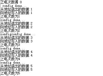
**********
/** ****************************************************************************** * @file EXTI/EXTI_Config/main.c * @author MCD Application Team * @version V3.5.0 * @date 08-April-2011 * @brief Main program body ****************************************************************************** * @attention * * THE PRESENT FIRMWARE WHICH IS FOR GUIDANCE ONLY AIMS AT PROVIDING CUSTOMERS * WITH CODING INFORMATION REGARDING THEIR PRODUCTS IN ORDER FOR THEM TO SAVE * TIME. AS A RESULT, STMICROELECTRONICS SHALL NOT BE HELD LIABLE FOR ANY * DIRECT, INDIRECT OR CONSEQUENTIAL DAMAGES WITH RESPECT TO ANY CLAIMS ARISING * FROM THE CONTENT OF SUCH FIRMWARE AND/OR THE USE MADE BY CUSTOMERS OF THE * CODING INFORMATION CONTAINED HEREIN IN CONNECTION WITH THEIR PRODUCTS. * * <h2><center>© COPYRIGHT 2011 STMicroelectronics</center></h2> ****************************************************************************** */ /* Includes ------------------------------------------------------------------*/ #include "stm32f10x.h" #include "stm32_eval.h" #include "delay.h" #include <stdio.h> #define VREF 3.3 unsigned char i=0; /** @addtogroup STM32F10x_StdPeriph_Examples * @{ */ /** @addtogroup EXTI_Config * @{ */ /* Private typedef -----------------------------------------------------------*/ /* Private define ------------------------------------------------------------*/ /* Private macro -------------------------------------------------------------*/ /* Private variables ---------------------------------------------------------*/ GPIO_InitTypeDef GPIO_InitStructure; USART_InitTypeDef USART_InitStructure; USART_ClockInitTypeDef USART_ClockInitStructure; void RCC_Configuration(void) { RCC_DeInit(); RCC_HSICmd(ENABLE); while(RCC_GetFlagStatus(RCC_FLAG_HSIRDY) == RESET); RCC_SYSCLKConfig(RCC_SYSCLKSource_HSI); RCC_HSEConfig(RCC_HSE_OFF); RCC_LSEConfig(RCC_LSE_OFF); RCC_PLLConfig(RCC_PLLSource_HSI_Div2,RCC_PLLMul_9); // 72HMz RCC_PLLCmd(ENABLE); while(RCC_GetFlagStatus(RCC_FLAG_PLLRDY) == RESET); RCC_ADCCLKConfig(RCC_PCLK2_Div4); RCC_PCLK2Config(RCC_HCLK_Div1); RCC_PCLK1Config(RCC_HCLK_Div2); RCC_HCLKConfig(RCC_SYSCLK_Div1); RCC_SYSCLKConfig(RCC_SYSCLKSource_PLLCLK); while(RCC_GetSYSCLKSource() != 0x08); //SystemInit(); RCC_APB2PeriphClockCmd(RCC_APB2Periph_GPIOD|RCC_APB2Periph_AFIO, ENABLE); GPIO_PinRemapConfig(GPIO_Remap_SWJ_JTAGDisable,ENABLE);//disable JTAG RCC_APB2PeriphClockCmd(RCC_APB2Periph_GPIOD|RCC_APB2Periph_AFIO, ENABLE); GPIO_PinRemapConfig(GPIO_Remap_SWJ_JTAGDisable,ENABLE);//disable JTAG GPIO_InitStructure.GPIO_Pin = GPIO_Pin_2; GPIO_InitStructure.GPIO_Speed = GPIO_Speed_50MHz; GPIO_InitStructure.GPIO_Mode = GPIO_Mode_Out_PP; GPIO_Init(GPIOD, &GPIO_InitStructure); GPIO_ResetBits(GPIOD,GPIO_Pin_2); RCC_APB2PeriphClockCmd(RCC_APB2Periph_GPIOC|RCC_APB2Periph_AFIO, ENABLE); GPIO_PinRemapConfig(GPIO_Remap_SWJ_JTAGDisable,ENABLE);//disable JTAG GPIO_InitStructure.GPIO_Pin = GPIO_Pin_0|GPIO_Pin_1|GPIO_Pin_2|GPIO_Pin_3|GPIO_Pin_4|GPIO_Pin_5|GPIO_Pin_6|GPIO_Pin_7; GPIO_InitStructure.GPIO_Speed = GPIO_Speed_50MHz; GPIO_InitStructure.GPIO_Mode = GPIO_Mode_Out_PP; GPIO_Init(GPIOC, &GPIO_InitStructure); GPIO_SetBits(GPIOC,GPIO_Pin_0|GPIO_Pin_1|GPIO_Pin_2|GPIO_Pin_3|GPIO_Pin_4|GPIO_Pin_5|GPIO_Pin_6|GPIO_Pin_7); RCC_APB1PeriphClockCmd(RCC_APB1Periph_TIM2, ENABLE); } void USART_int(long BaudRate) { RCC_APB2PeriphClockCmd(RCC_APB2Periph_GPIOA|RCC_APB2Periph_USART1,ENABLE); GPIO_InitStructure.GPIO_Pin = GPIO_Pin_9; GPIO_InitStructure.GPIO_Speed = GPIO_Speed_50MHz; GPIO_InitStructure.GPIO_Mode = GPIO_Mode_AF_PP; GPIO_Init(GPIOA, &GPIO_InitStructure); /* PA10 USART1_Rx */ GPIO_InitStructure.GPIO_Pin = GPIO_Pin_10; GPIO_InitStructure.GPIO_Mode = GPIO_Mode_IN_FLOATING; GPIO_Init(GPIOA, &GPIO_InitStructure); /* USARTx configured as follow: - BaudRate = 115200 baud - Word Length = 8 Bits - One Stop Bit - No parity - Hardware flow control disabled (RTS and CTS signals) - Receive and transmit enabled */ USART_InitStructure.USART_BaudRate = BaudRate;//?????? USART_InitStructure.USART_WordLength = USART_WordLength_8b;//???????8bit USART_InitStructure.USART_StopBits = USART_StopBits_1;//????1 USART_InitStructure.USART_Parity = USART_Parity_No;//???? USART_InitStructure.USART_HardwareFlowControl = USART_HardwareFlowControl_None;//??????none USART_InitStructure.USART_Mode = USART_Mode_Rx | USART_Mode_Tx;//?????????? USART_ClockInitStructure.USART_Clock = USART_Clock_Disable; USART_ClockInitStructure.USART_CPOL = USART_CPOL_Low; USART_ClockInitStructure.USART_CPHA = USART_CPHA_2Edge; USART_ClockInitStructure.USART_LastBit = USART_LastBit_Disable; USART_ClockInit(USART1, &USART_ClockInitStructure); USART_Init(USART1, &USART_InitStructure); USART_Cmd(USART1, ENABLE); USART_ITConfig(USART1, USART_IT_RXNE, ENABLE); USART_Cmd(USART1, ENABLE); } void GPIO_INIT() { RCC_Configuration(); RCC_APB2PeriphClockCmd(RCC_APB2Periph_GPIOC, ENABLE); GPIO_InitStructure.GPIO_Pin = GPIO_Pin_8|GPIO_Pin_9|GPIO_Pin_10|GPIO_Pin_11; GPIO_InitStructure.GPIO_Speed = GPIO_Speed_50MHz; GPIO_InitStructure.GPIO_Mode = GPIO_Mode_IN_FLOATING; GPIO_Init(GPIOC, &GPIO_InitStructure); RCC_APB2PeriphClockCmd(RCC_APB2Periph_GPIOB, ENABLE); GPIO_InitStructure.GPIO_Pin = GPIO_Pin_1|GPIO_Pin_5|GPIO_Pin_6|GPIO_Pin_7|GPIO_Pin_8|GPIO_Pin_9|GPIO_Pin_12|GPIO_Pin_13|GPIO_Pin_14|GPIO_Pin_15; GPIO_InitStructure.GPIO_Speed = GPIO_Speed_50MHz; GPIO_InitStructure.GPIO_Mode = GPIO_Mode_Out_PP; GPIO_Init(GPIOB, &GPIO_InitStructure); } void Iic1_Init(void) { GPIO_InitTypeDef GPIO_InitStructure; I2C_InitTypeDef I2C_InitStructure; RCC_APB2PeriphClockCmd(RCC_APB2Periph_GPIOB, ENABLE); RCC_APB1PeriphClockCmd(RCC_APB1Periph_I2C2, ENABLE); //PB6-I2C2_SCL PB7-I2C2_SDA PB10-I2C2_SCL PB11-I2C2_SDA /* Configure IO connected to IIC*********************/ GPIO_InitStructure.GPIO_Pin = GPIO_Pin_10 | GPIO_Pin_11; GPIO_InitStructure.GPIO_Speed = GPIO_Speed_50MHz; GPIO_InitStructure.GPIO_Mode = GPIO_Mode_AF_OD; GPIO_Init(GPIOB, &GPIO_InitStructure); I2C_InitStructure.I2C_Mode = I2C_Mode_I2C; I2C_InitStructure.I2C_DutyCycle = I2C_DutyCycle_2; I2C_InitStructure.I2C_OwnAddress1 = 0xA0; I2C_InitStructure.I2C_Ack = I2C_Ack_Enable; I2C_InitStructure.I2C_AcknowledgedAddress = I2C_AcknowledgedAddress_7bit; I2C_InitStructure.I2C_ClockSpeed = 400000; I2C_Cmd(I2C2, ENABLE); I2C_Init(I2C2, &I2C_InitStructure); I2C_AcknowledgeConfig(I2C2, ENABLE); } /**********************************************************************/ /*IIC????? */ /* */ /**********************************************************************/ void I2C2_WriteByte(unsigned char id,unsigned char write_address,unsigned char byte) { while(I2C_GetFlagStatus(I2C2, I2C_FLAG_BUSY));//检查标志位设置与否-总线忙标志位 I2C_GenerateSTART(I2C2,ENABLE);//产生i2c2传输开始条件 while(!I2C_CheckEvent(I2C2, I2C_EVENT_MASTER_MODE_SELECT));//检查最近一次i2c是否是输入事件 I2C_Send7bitAddress(I2C2,id,I2C_Direction_Transmitter);//向指定的从i2c设备传输地址字 while(!I2C_CheckEvent(I2C2, I2C_EVENT_MASTER_TRANSMITTER_MODE_SELECTED)); I2C_SendData(I2C2, write_address);//通过i2c发送一个数据 while(!I2C_CheckEvent(I2C2, I2C_EVENT_MASTER_BYTE_TRANSMITTED)); I2C_SendData(I2C2, byte); while(!I2C_CheckEvent(I2C2, I2C_EVENT_MASTER_BYTE_TRANSMITTED)); I2C_GenerateSTOP(I2C2, ENABLE);//产生i2c2传输停止条件 do { /* Send START condition */ I2C_GenerateSTART(I2C2, ENABLE); /* Read I2C2 SR1 register */ /* Send EEPROM address for write */ I2C_Send7bitAddress(I2C2, 0xA0, I2C_Direction_Transmitter); }while(!(I2C_ReadRegister(I2C2, I2C_Register_SR1) & 0x0002));//读取指定的i2c寄存器并返回其值 /* Clear AF flag */ I2C_ClearFlag(I2C2, I2C_FLAG_AF); /* STOP condition */ I2C_GenerateSTOP(I2C2, ENABLE); } unsigned char I2C2_ReadByte(unsigned char id, unsigned char read_address) { unsigned char temp; while(I2C_GetFlagStatus(I2C2, I2C_FLAG_BUSY)){} I2C_GenerateSTART(I2C2, ENABLE); while(!I2C_CheckEvent(I2C2, I2C_EVENT_MASTER_MODE_SELECT)); I2C_Send7bitAddress(I2C2, id, I2C_Direction_Transmitter); while(!I2C_CheckEvent(I2C2, I2C_EVENT_MASTER_TRANSMITTER_MODE_SELECTED)); I2C_Cmd(I2C2, ENABLE); I2C_SendData(I2C2, read_address); while(!I2C_CheckEvent(I2C2, I2C_EVENT_MASTER_BYTE_TRANSMITTED)); I2C_GenerateSTART(I2C2, ENABLE); while(!I2C_CheckEvent(I2C2, I2C_EVENT_MASTER_MODE_SELECT)); I2C_Send7bitAddress(I2C2, id, I2C_Direction_Receiver); while(!I2C_CheckEvent(I2C2, I2C_EVENT_MASTER_RECEIVER_MODE_SELECTED)); I2C_AcknowledgeConfig(I2C2, DISABLE); I2C_GenerateSTOP(I2C2, ENABLE); while(!(I2C_CheckEvent(I2C2, I2C_EVENT_MASTER_BYTE_RECEIVED))); temp = I2C_ReceiveData(I2C2); I2C_AcknowledgeConfig(I2C2, ENABLE); return temp; } int table[10]= {GPIO_Pin_7|GPIO_Pin_9|GPIO_Pin_12|GPIO_Pin_14|GPIO_Pin_13|GPIO_Pin_8 ,GPIO_Pin_9|GPIO_Pin_12 ,GPIO_Pin_7|GPIO_Pin_9|GPIO_Pin_14|GPIO_Pin_13|GPIO_Pin_5, GPIO_Pin_7|GPIO_Pin_9|GPIO_Pin_12|GPIO_Pin_14|GPIO_Pin_5,GPIO_Pin_9|GPIO_Pin_12|GPIO_Pin_8|GPIO_Pin_5,GPIO_Pin_7|GPIO_Pin_12|GPIO_Pin_14|GPIO_Pin_8|GPIO_Pin_5, GPIO_Pin_7|GPIO_Pin_12|GPIO_Pin_14|GPIO_Pin_13|GPIO_Pin_8|GPIO_Pin_5,GPIO_Pin_7|GPIO_Pin_9|GPIO_Pin_12, GPIO_Pin_5|GPIO_Pin_7|GPIO_Pin_8|GPIO_Pin_9|GPIO_Pin_12|GPIO_Pin_13|GPIO_Pin_14,GPIO_Pin_5|GPIO_Pin_7|GPIO_Pin_8|GPIO_Pin_9|GPIO_Pin_12|GPIO_Pin_14 }; void IIC_TEST() { printf(" config done...\r\n"); i = I2C2_ReadByte(0xA0,0); i++; printf("从地址读出的数据:%d\r\n",i); I2C2_WriteByte(0xA0,0,i); printf("向地址写入的数据:%d\r\n",i); printf("上电次数为%d\r\n",i); /*for(i=0;i<5;i++) { I2C2_WriteByte(0xA0,i,buff[i]); printf("向地址0x0%x写入数据:%d\r\n",i,buff[i]); delay_ms(1000); temp=I2C2_ReadByte(0xA0,i); printf("从地址0x0%x读出的数据:%d\r\n",i,temp); delay_ms(1000); if(buff[i] == temp) {printf("第%x次IIC读写测试成功!!\r\n",i+1);delay_ms(1000);} else {printf("第%x次IIC读写失败!!\r\n",i+1);delay_ms(1000);} }*/ } void func() { char g,s; g=i%10; s=i/10; while(1) { GPIO_SetBits(GPIOB,GPIO_Pin_15); GPIO_ResetBits(GPIOB,table[s]); delay_ms(5); GPIO_ResetBits(GPIOB,GPIO_Pin_15); GPIO_SetBits(GPIOB,GPIO_Pin_5|GPIO_Pin_6|GPIO_Pin_7|GPIO_Pin_8|GPIO_Pin_9|GPIO_Pin_12|GPIO_Pin_13|GPIO_Pin_14); //动态扫描 GPIO_SetBits(GPIOB,GPIO_Pin_1); GPIO_ResetBits(GPIOB,table[g]); delay_ms(5); GPIO_ResetBits(GPIOB,GPIO_Pin_1); GPIO_SetBits(GPIOB,GPIO_Pin_5|GPIO_Pin_6|GPIO_Pin_7|GPIO_Pin_8|GPIO_Pin_9|GPIO_Pin_12|GPIO_Pin_13|GPIO_Pin_14); if(!GPIO_ReadInputDataBit(GPIOC,GPIO_Pin_8)) { delay_ms(200); I2C2_WriteByte(0xA0,0,0); printf("上电次数清 0\r\n ");} } } int main(void) { /*!< At this stage the microcontroller clock setting is already configured, this is done through SystemInit() function which is called from startup file (startup_stm32f10x_xx.s) before to branch to application main. To reconfigure the default setting of SystemInit() function, refer to system_stm32f10x.c file */ /* System Clocks Configuration */ RCC_Configuration(); GPIO_INIT(); USART_int(115200); Iic1_Init(); IIC_TEST(); func(); } #ifdef USE_FULL_ASSERT void assert_failed(uint8_t* file, uint32_t line) { while (1) { } } #endif #ifdef __GNUC__ #define PUTCHAR_PROTOTYPE int __io_putchar(int ch) #else #define PUTCHAR_PROTOTYPE int fputc(int ch, FILE *f) #endif /* __GNUC__ */ PUTCHAR_PROTOTYPE { USART_SendData(EVAL_COM1, (uint8_t) ch); while (USART_GetFlagStatus(EVAL_COM1, USART_FLAG_TC) == RESET) {} return ch; }
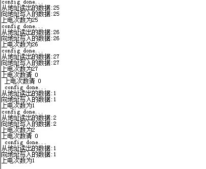
IIC--上电计数 外部中断清零
/**
******************************************************************************
* @file EXTI/EXTI_Config/main.c
* @author MCD Application Team
* @version V3.5.0
* @date 08-April-2011
* @brief Main program body
******************************************************************************
* @attention
*
* THE PRESENT FIRMWARE WHICH IS FOR GUIDANCE ONLY AIMS AT PROVIDING CUSTOMERS
* WITH CODING INFORMATION REGARDING THEIR PRODUCTS IN ORDER FOR THEM TO SAVE
* TIME. AS A RESULT, STMICROELECTRONICS SHALL NOT BE HELD LIABLE FOR ANY
* DIRECT, INDIRECT OR CONSEQUENTIAL DAMAGES WITH RESPECT TO ANY CLAIMS ARISING
* FROM THE CONTENT OF SUCH FIRMWARE AND/OR THE USE MADE BY CUSTOMERS OF THE
* CODING INFORMATION CONTAINED HEREIN IN CONNECTION WITH THEIR PRODUCTS.
*
* <h2><center>© COPYRIGHT 2011 STMicroelectronics</center></h2>
******************************************************************************
*/
/* Includes ------------------------------------------------------------------*/
#include "stm32f10x.h"
#include "stm32_eval.h"
#include "delay.h"
#include <stdio.h>
#define VREF 3.3
unsigned char i=0;
/** @addtogroup STM32F10x_StdPeriph_Examples
* @{
*/
/** @addtogroup EXTI_Config
* @{
*/
/* Private typedef -----------------------------------------------------------*/
/* Private define ------------------------------------------------------------*/
/* Private macro -------------------------------------------------------------*/
/* Private variables ---------------------------------------------------------*/
EXTI_InitTypeDef EXTI_InitStructure;
NVIC_InitTypeDef NVIC_InitStructure;
GPIO_InitTypeDef GPIO_InitStructure;
USART_InitTypeDef USART_InitStructure;
USART_ClockInitTypeDef USART_ClockInitStructure;
void RCC_Configuration(void)
{
RCC_DeInit();
RCC_HSICmd(ENABLE);
while(RCC_GetFlagStatus(RCC_FLAG_HSIRDY) == RESET);
RCC_SYSCLKConfig(RCC_SYSCLKSource_HSI);
RCC_HSEConfig(RCC_HSE_OFF);
RCC_LSEConfig(RCC_LSE_OFF);
RCC_PLLConfig(RCC_PLLSource_HSI_Div2,RCC_PLLMul_9); // 72HMz
RCC_PLLCmd(ENABLE);
while(RCC_GetFlagStatus(RCC_FLAG_PLLRDY) == RESET);
RCC_ADCCLKConfig(RCC_PCLK2_Div4);
RCC_PCLK2Config(RCC_HCLK_Div1);
RCC_PCLK1Config(RCC_HCLK_Div2);
RCC_HCLKConfig(RCC_SYSCLK_Div1);
RCC_SYSCLKConfig(RCC_SYSCLKSource_PLLCLK);
while(RCC_GetSYSCLKSource() != 0x08);
//SystemInit();
RCC_APB2PeriphClockCmd(RCC_APB2Periph_GPIOD|RCC_APB2Periph_AFIO, ENABLE);
GPIO_PinRemapConfig(GPIO_Remap_SWJ_JTAGDisable,ENABLE);//disable JTAG
RCC_APB2PeriphClockCmd(RCC_APB2Periph_GPIOD|RCC_APB2Periph_AFIO, ENABLE);
GPIO_PinRemapConfig(GPIO_Remap_SWJ_JTAGDisable,ENABLE);//disable JTAG
GPIO_InitStructure.GPIO_Pin = GPIO_Pin_2;
GPIO_InitStructure.GPIO_Speed = GPIO_Speed_50MHz;
GPIO_InitStructure.GPIO_Mode = GPIO_Mode_Out_PP;
GPIO_Init(GPIOD, &GPIO_InitStructure);
GPIO_ResetBits(GPIOD,GPIO_Pin_2);
RCC_APB2PeriphClockCmd(RCC_APB2Periph_GPIOC|RCC_APB2Periph_AFIO, ENABLE);
GPIO_PinRemapConfig(GPIO_Remap_SWJ_JTAGDisable,ENABLE);//disable JTAG
GPIO_InitStructure.GPIO_Pin = GPIO_Pin_0|GPIO_Pin_1|GPIO_Pin_2|GPIO_Pin_3|GPIO_Pin_4|GPIO_Pin_5|GPIO_Pin_6|GPIO_Pin_7;
GPIO_InitStructure.GPIO_Speed = GPIO_Speed_50MHz;
GPIO_InitStructure.GPIO_Mode = GPIO_Mode_Out_PP;
GPIO_Init(GPIOC, &GPIO_InitStructure);
GPIO_SetBits(GPIOC,GPIO_Pin_0|GPIO_Pin_1|GPIO_Pin_2|GPIO_Pin_3|GPIO_Pin_4|GPIO_Pin_5|GPIO_Pin_6|GPIO_Pin_7);
RCC_APB1PeriphClockCmd(RCC_APB1Periph_TIM2, ENABLE);
}
void USART_int(long BaudRate)
{
RCC_APB2PeriphClockCmd(RCC_APB2Periph_GPIOA|RCC_APB2Periph_USART1,ENABLE);
GPIO_InitStructure.GPIO_Pin = GPIO_Pin_9;
GPIO_InitStructure.GPIO_Speed = GPIO_Speed_50MHz;
GPIO_InitStructure.GPIO_Mode = GPIO_Mode_AF_PP;
GPIO_Init(GPIOA, &GPIO_InitStructure);
/* PA10 USART1_Rx */
GPIO_InitStructure.GPIO_Pin = GPIO_Pin_10;
GPIO_InitStructure.GPIO_Mode = GPIO_Mode_IN_FLOATING;
GPIO_Init(GPIOA, &GPIO_InitStructure);
/* USARTx configured as follow:
- BaudRate = 115200 baud
- Word Length = 8 Bits
- One Stop Bit
- No parity
- Hardware flow control disabled (RTS and CTS signals)
- Receive and transmit enabled
*/
USART_InitStructure.USART_BaudRate = BaudRate;//??????
USART_InitStructure.USART_WordLength = USART_WordLength_8b;//???????8bit
USART_InitStructure.USART_StopBits = USART_StopBits_1;//????1
USART_InitStructure.USART_Parity = USART_Parity_No;//????
USART_InitStructure.USART_HardwareFlowControl = USART_HardwareFlowControl_None;//??????none
USART_InitStructure.USART_Mode = USART_Mode_Rx | USART_Mode_Tx;//??????????
USART_ClockInitStructure.USART_Clock = USART_Clock_Disable;
USART_ClockInitStructure.USART_CPOL = USART_CPOL_Low;
USART_ClockInitStructure.USART_CPHA = USART_CPHA_2Edge;
USART_ClockInitStructure.USART_LastBit = USART_LastBit_Disable;
USART_ClockInit(USART1, &USART_ClockInitStructure);
USART_Init(USART1, &USART_InitStructure);
USART_Cmd(USART1, ENABLE);
USART_ITConfig(USART1, USART_IT_RXNE, ENABLE);
USART_Cmd(USART1, ENABLE);
}
void GPIO_INIT()
{
RCC_Configuration();
RCC_APB2PeriphClockCmd(RCC_APB2Periph_GPIOC, ENABLE);
GPIO_InitStructure.GPIO_Pin = GPIO_Pin_8|GPIO_Pin_9|GPIO_Pin_10|GPIO_Pin_11;
GPIO_InitStructure.GPIO_Speed = GPIO_Speed_50MHz;
GPIO_InitStructure.GPIO_Mode = GPIO_Mode_IN_FLOATING;
GPIO_Init(GPIOC, &GPIO_InitStructure);
RCC_APB2PeriphClockCmd(RCC_APB2Periph_GPIOB, ENABLE);
GPIO_InitStructure.GPIO_Pin = GPIO_Pin_1|GPIO_Pin_5|GPIO_Pin_6|GPIO_Pin_7|GPIO_Pin_8|GPIO_Pin_9|GPIO_Pin_12|GPIO_Pin_13|GPIO_Pin_14|GPIO_Pin_15;
GPIO_InitStructure.GPIO_Speed = GPIO_Speed_50MHz;
GPIO_InitStructure.GPIO_Mode = GPIO_Mode_Out_PP;
GPIO_Init(GPIOB, &GPIO_InitStructure);
}
void Iic1_Init(void)
{
GPIO_InitTypeDef GPIO_InitStructure;
I2C_InitTypeDef I2C_InitStructure;
RCC_APB2PeriphClockCmd(RCC_APB2Periph_GPIOB, ENABLE);
RCC_APB1PeriphClockCmd(RCC_APB1Periph_I2C2, ENABLE);
//PB6-I2C2_SCL PB7-I2C2_SDA PB10-I2C2_SCL PB11-I2C2_SDA
/* Configure IO connected to IIC*********************/
GPIO_InitStructure.GPIO_Pin = GPIO_Pin_10 | GPIO_Pin_11;
GPIO_InitStructure.GPIO_Speed = GPIO_Speed_50MHz;
GPIO_InitStructure.GPIO_Mode = GPIO_Mode_AF_OD;
GPIO_Init(GPIOB, &GPIO_InitStructure);
I2C_InitStructure.I2C_Mode = I2C_Mode_I2C;
I2C_InitStructure.I2C_DutyCycle = I2C_DutyCycle_2;
I2C_InitStructure.I2C_OwnAddress1 = 0xA0;
I2C_InitStructure.I2C_Ack = I2C_Ack_Enable;
I2C_InitStructure.I2C_AcknowledgedAddress = I2C_AcknowledgedAddress_7bit;
I2C_InitStructure.I2C_ClockSpeed = 400000;
I2C_Cmd(I2C2, ENABLE);
I2C_Init(I2C2, &I2C_InitStructure);
I2C_AcknowledgeConfig(I2C2, ENABLE);
}
/**********************************************************************/
/*IIC????? */
/* */
/**********************************************************************/
void I2C2_WriteByte(unsigned char id,unsigned char write_address,unsigned char byte)
{
while(I2C_GetFlagStatus(I2C2, I2C_FLAG_BUSY));//检查标志位设置与否-总线忙标志位
I2C_GenerateSTART(I2C2,ENABLE);//产生i2c2传输开始条件
while(!I2C_CheckEvent(I2C2, I2C_EVENT_MASTER_MODE_SELECT));//检查最近一次i2c是否是输入事件
I2C_Send7bitAddress(I2C2,id,I2C_Direction_Transmitter);//向指定的从i2c设备传输地址字
while(!I2C_CheckEvent(I2C2, I2C_EVENT_MASTER_TRANSMITTER_MODE_SELECTED));
I2C_SendData(I2C2, write_address);//通过i2c发送一个数据
while(!I2C_CheckEvent(I2C2, I2C_EVENT_MASTER_BYTE_TRANSMITTED));
I2C_SendData(I2C2, byte);
while(!I2C_CheckEvent(I2C2, I2C_EVENT_MASTER_BYTE_TRANSMITTED));
I2C_GenerateSTOP(I2C2, ENABLE);//产生i2c2传输停止条件
do
{
/* Send START condition */
I2C_GenerateSTART(I2C2, ENABLE);
/* Read I2C2 SR1 register */
/* Send EEPROM address for write */
I2C_Send7bitAddress(I2C2, 0xA0, I2C_Direction_Transmitter);
}while(!(I2C_ReadRegister(I2C2, I2C_Register_SR1) & 0x0002));//读取指定的i2c寄存器并返回其值
/* Clear AF flag */
I2C_ClearFlag(I2C2, I2C_FLAG_AF);
/* STOP condition */
I2C_GenerateSTOP(I2C2, ENABLE);
}
unsigned char I2C2_ReadByte(unsigned char id, unsigned char read_address)
{
unsigned char temp;
while(I2C_GetFlagStatus(I2C2, I2C_FLAG_BUSY)){}
I2C_GenerateSTART(I2C2, ENABLE);
while(!I2C_CheckEvent(I2C2, I2C_EVENT_MASTER_MODE_SELECT));
I2C_Send7bitAddress(I2C2, id, I2C_Direction_Transmitter);
while(!I2C_CheckEvent(I2C2, I2C_EVENT_MASTER_TRANSMITTER_MODE_SELECTED));
I2C_Cmd(I2C2, ENABLE);
I2C_SendData(I2C2, read_address);
while(!I2C_CheckEvent(I2C2, I2C_EVENT_MASTER_BYTE_TRANSMITTED));
I2C_GenerateSTART(I2C2, ENABLE);
while(!I2C_CheckEvent(I2C2, I2C_EVENT_MASTER_MODE_SELECT));
I2C_Send7bitAddress(I2C2, id, I2C_Direction_Receiver);
while(!I2C_CheckEvent(I2C2, I2C_EVENT_MASTER_RECEIVER_MODE_SELECTED));
I2C_AcknowledgeConfig(I2C2, DISABLE);
I2C_GenerateSTOP(I2C2, ENABLE);
while(!(I2C_CheckEvent(I2C2, I2C_EVENT_MASTER_BYTE_RECEIVED)));
temp = I2C_ReceiveData(I2C2);
I2C_AcknowledgeConfig(I2C2, ENABLE);
return temp;
}
int table[10]=
{GPIO_Pin_7|GPIO_Pin_9|GPIO_Pin_12|GPIO_Pin_14|GPIO_Pin_13|GPIO_Pin_8 ,GPIO_Pin_9|GPIO_Pin_12 ,GPIO_Pin_7|GPIO_Pin_9|GPIO_Pin_14|GPIO_Pin_13|GPIO_Pin_5,
GPIO_Pin_7|GPIO_Pin_9|GPIO_Pin_12|GPIO_Pin_14|GPIO_Pin_5,GPIO_Pin_9|GPIO_Pin_12|GPIO_Pin_8|GPIO_Pin_5,GPIO_Pin_7|GPIO_Pin_12|GPIO_Pin_14|GPIO_Pin_8|GPIO_Pin_5,
GPIO_Pin_7|GPIO_Pin_12|GPIO_Pin_14|GPIO_Pin_13|GPIO_Pin_8|GPIO_Pin_5,GPIO_Pin_7|GPIO_Pin_9|GPIO_Pin_12,
GPIO_Pin_5|GPIO_Pin_7|GPIO_Pin_8|GPIO_Pin_9|GPIO_Pin_12|GPIO_Pin_13|GPIO_Pin_14,GPIO_Pin_5|GPIO_Pin_7|GPIO_Pin_8|GPIO_Pin_9|GPIO_Pin_12|GPIO_Pin_14
};
void EXTIkeyS1_Config(void)
{
/* Enable GPIOA clock */
RCC_APB2PeriphClockCmd(RCC_APB2Periph_GPIOC, ENABLE);
/* Configure PA.00 pin as input floating */
GPIO_InitStructure.GPIO_Pin = GPIO_Pin_8;
GPIO_InitStructure.GPIO_Mode = GPIO_Mode_IN_FLOATING;
GPIO_Init(GPIOC, &GPIO_InitStructure);
/* Enable AFIO clock */
RCC_APB2PeriphClockCmd(RCC_APB2Periph_AFIO, ENABLE);
GPIO_EXTILineConfig(GPIO_PortSourceGPIOC, GPIO_PinSource8);
EXTI_InitStructure.EXTI_Line = EXTI_Line8;
EXTI_InitStructure.EXTI_Mode = EXTI_Mode_Interrupt;
EXTI_InitStructure.EXTI_Trigger = EXTI_Trigger_Falling;
EXTI_InitStructure.EXTI_LineCmd = ENABLE;
EXTI_Init(&EXTI_InitStructure);
NVIC_InitStructure.NVIC_IRQChannel = EXTI9_5_IRQn;
NVIC_InitStructure.NVIC_IRQChannelPreemptionPriority = 0x0F;
NVIC_InitStructure.NVIC_IRQChannelSubPriority = 0x0F;
NVIC_InitStructure.NVIC_IRQChannelCmd = ENABLE;
NVIC_Init(&NVIC_InitStructure);
}
void EXTI9_5_IRQHandler(void)
{
if(EXTI_GetITStatus(EXTI_Line8) != RESET)
{
I2C2_WriteByte(0xA0,0,0);
printf("上电次数清 0\r\n ");
/* Clear the EXTI line 8 pending bit */
EXTI_ClearITPendingBit(EXTI_Line8);
}
}
void IIC_TEST()
{
printf(" config done...\r\n");
i = I2C2_ReadByte(0xA0,0);
i++;
printf("从地址读出的数据:%d\r\n",i);
I2C2_WriteByte(0xA0,0,i);
printf("向地址写入的数据:%d\r\n",i);
printf("上电次数为%d\r\n",i);
/*for(i=0;i<5;i++)
{
I2C2_WriteByte(0xA0,i,buff[i]);
printf("向地址0x0%x写入数据:%d\r\n",i,buff[i]);
delay_ms(1000);
temp=I2C2_ReadByte(0xA0,i);
printf("从地址0x0%x读出的数据:%d\r\n",i,temp);
delay_ms(1000);
if(buff[i] == temp)
{printf("第%x次IIC读写测试成功!!\r\n",i+1);delay_ms(1000);}
else {printf("第%x次IIC读写失败!!\r\n",i+1);delay_ms(1000);}
}*/
}
void func()
{
char g,s;
g=i%10;
s=i/10;
while(1)
{
GPIO_SetBits(GPIOB,GPIO_Pin_15);
GPIO_ResetBits(GPIOB,table[s]);
delay_ms(5);
GPIO_ResetBits(GPIOB,GPIO_Pin_15);
GPIO_SetBits(GPIOB,GPIO_Pin_5|GPIO_Pin_6|GPIO_Pin_7|GPIO_Pin_8|GPIO_Pin_9|GPIO_Pin_12|GPIO_Pin_13|GPIO_Pin_14);
//动态扫描
GPIO_SetBits(GPIOB,GPIO_Pin_1);
GPIO_ResetBits(GPIOB,table[g]);
delay_ms(5);
GPIO_ResetBits(GPIOB,GPIO_Pin_1);
GPIO_SetBits(GPIOB,GPIO_Pin_5|GPIO_Pin_6|GPIO_Pin_7|GPIO_Pin_8|GPIO_Pin_9|GPIO_Pin_12|GPIO_Pin_13|GPIO_Pin_14);
}
}
int main(void)
{
/*!< At this stage the microcontroller clock setting is already configured,
this is done through SystemInit() function which is called from startup
file (startup_stm32f10x_xx.s) before to branch to application main.
To reconfigure the default setting of SystemInit() function, refer to
system_stm32f10x.c file
*/
/* System Clocks Configuration */
RCC_Configuration();
EXTIkeyS1_Config();
GPIO_INIT();
USART_int(115200);
Iic1_Init();
IIC_TEST();
func();
}
#ifdef USE_FULL_ASSERT
void assert_failed(uint8_t* file, uint32_t line)
{
while (1)
{
}
}
#endif
#ifdef __GNUC__
#define PUTCHAR_PROTOTYPE int __io_putchar(int ch)
#else
#define PUTCHAR_PROTOTYPE int fputc(int ch, FILE *f)
#endif /* __GNUC__ */
PUTCHAR_PROTOTYPE
{
USART_SendData(EVAL_COM1, (uint8_t) ch);
while (USART_GetFlagStatus(EVAL_COM1, USART_FLAG_TC) == RESET)
{}
return ch;
}
回复
 我要赚赏金打赏帖 我要赚赏金打赏帖 |
|
|---|---|
| 片外存储Flash使用方法(Arduino IDE环境)被打赏¥22元 | |
| 三分钟快速上手ESP-NOW(ArduinoIDE环境)被打赏¥23元 | |
| 【S32K3XX】LPSPI参数配置说明被打赏¥21元 | |
| 在WT9932C61-TINY上实现超声波测距被打赏¥22元 | |
| 基于WT9932C61-TINY的环境构建及OLED屏驱动测试被打赏¥20元 | |
| 【S32K3XX】Core-to-Core 中断使用被打赏¥21元 | |
| 「AI编程记录--含源码」用一晚上的时间写一个esp32的示波器被打赏¥19元 | |
| STM32C0116DK开发探索记(3)被打赏¥30元 | |
| STM32C0116DK开发探索记(2)被打赏¥24元 | |
| STM32C0116DK开发探索记(1)被打赏¥29元 | |
 STM32
STM32 MCU
MCU 通讯及无线技术
 物联网技术
物联网技术 电子DIY
电子DIY 板卡试用
板卡试用 基础知识
基础知识 软件与操作系统
 我爱生活
我爱生活 小e食堂
小e食堂

