
其实都调用了个GPIO初始化的操作
比如我们的程序中:
DigitalOut myled(LED1);
这个是啥意思呢
其实就是告诉MCU,这个GPIO PIN是干啥的
以及进行一些基本的设置
mbed官网中的例子,和我们这个例子都直接用mbed的API
回头我们再研究它到底干啥啦

在回头看这个层次结构图
现在我们对MCU寄存器有些概念啦,对mbed API也有些概念啦
并且分别用mbed API和直接操作寄存器的方式,实现了两个版本的blink.
#include "mbed.h"
DigitalOut myled(LED1);

int main() {
    while(1) {
        myled = 1; // LED is ON
        wait(1); // 1 sec
        myled = 0; // LED is OFF
        wait(1); // 1 sec
    }
}
#include <mbed.h>
DigitalOut myled(LED1);

int main() {

		unsigned int mask_pin5 = 1 << 5;
    volatile unsigned int *porta_set = (unsigned int *)0x50000018;
    volatile unsigned int *porta_clr = (unsigned int *)0x50000018;

    while (true) {
        *porta_set |= mask_pin5;
        wait(0.5);

        *porta_clr |= (mask_pin5 << 16);
        wait(0.5);
    }
}
 代码到处复制可以避免代码丢失
这几个字母我都认识,放一起就不知道是啥啦
费了好大劲
找到这样一个链接
http://www.arm.com/products/processors/cortex-m/cortex-microcontroller-software-interface-standard.php
原来是这个意思:
CMSIS - Cortex Microcontroller Software Interface Standard
CMSIS - Cortex Microcontroller Software Interface Standard
![]() The ARM® Cortex® Microcontroller Software Interface Standard (CMSIS) is a vendor-independent hardware abstraction layer for the Cortex-M processor series and specifies debugger interfaces.Creation of software is a major cost factor in the embedded industry. By
standardizing the software interfaces across all Cortex-M silicon
vendor products, especially when creating new projects or migrating
existing software to a new device, means significant cost reductions.
The ARM® Cortex® Microcontroller Software Interface Standard (CMSIS) is a vendor-independent hardware abstraction layer for the Cortex-M processor series and specifies debugger interfaces.Creation of software is a major cost factor in the embedded industry. By
standardizing the software interfaces across all Cortex-M silicon
vendor products, especially when creating new projects or migrating
existing software to a new device, means significant cost reductions.
The CMSIS enables consistent and simple software interfaces to the processor for interface peripherals, real-time operating systems, and middleware. It simplifies software re-use, reducing the learning curve for new microcontroller developers and cutting the time-to-market for devices.
原来就是在硬件上抽象出来一个层次。这样操作起来就统一啦,也方便移植啦,也省费用啦....,貌似都没我啥事。
继续贴图,虽然我看不懂这是啥玩意。

/**
  * @brief General Purpose IO
  */

typedef struct
{
  __IO uint32_t MODER;        /*!< GPIO port mode register,                     Address offset: 0x00 */
  __IO uint32_t OTYPER;       /*!< GPIO port output type register,              Address offset: 0x04 */
  __IO uint32_t OSPEEDR;      /*!< GPIO port output speed register,             Address offset: 0x08 */
  __IO uint32_t PUPDR;        /*!< GPIO port pull-up/pull-down register,        Address offset: 0x0C */
  __IO uint32_t IDR;          /*!< GPIO port input data register,               Address offset: 0x10 */
  __IO uint32_t ODR;          /*!< GPIO port output data register,              Address offset: 0x14 */
  __IO uint32_t BSRR;         /*!< GPIO port bit set/reset registerBSRR,        Address offset: 0x18 */
  __IO uint32_t LCKR;         /*!< GPIO port configuration lock register,       Address offset: 0x1C */
  __IO uint32_t AFR[2];       /*!< GPIO alternate function register,            Address offset: 0x20-0x24 */
  __IO uint32_t BRR;          /*!< GPIO bit reset register,                     Address offset: 0x28 */
}GPIO_TypeDef;
寄存器的定义
和数据手册中(9.4 GPIO registers)此章节的内容是对应的。
#define GPIOA_BASE            (IOPPERIPH_BASE + 0x00000000)
#define GPIOB_BASE            (IOPPERIPH_BASE + 0x00000400)
#define GPIOC_BASE            (IOPPERIPH_BASE + 0x00000800)
#define GPIOD_BASE            (IOPPERIPH_BASE + 0x00000C00)
#define GPIOH_BASE            (IOPPERIPH_BASE + 0x00001C00)
GPIO的基地址
与数据手册中(2.2 Memory organization)此章节的内容是对应的。
接下来用这个再重写blink
官网上的例子:
Blinky example using CMSIS-CORE
Let's see how to blink an LED on our LPC1768 mbed using the CMSIS-CORE API:
#include "mbed.h"

// Reuse initialization code from the mbed library
DigitalOut led1(LED1); // P1_18

int main() {
    unsigned int mask_pin18 = 1 << 18;

    while (true) {
        LPC_GPIO1->FIOSET |= mask_pin18;
        wait(0.5);

        LPC_GPIO1->FIOCLR |= mask_pin18;
        wait(0.5);
    }
}
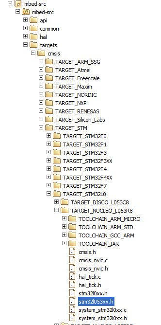
我们用NUCLEO L053R8实现的类似代码:
#include <mbed.h>
DigitalOut myled(LED1);

int main() {
	  unsigned int mask_pin5 = 1 << 5;

    while (true) {
        GPIOA->BSRR |= mask_pin5;
        wait(0.5);

        GPIOA->BSRR |=(mask_pin5 << 16);
        wait(0.5);
    }
}
下到板子里,哇,小灯闪闪。
 我要赚赏金打赏帖 我要赚赏金打赏帖 |
|
|---|---|
| 片外存储Flash使用方法(Arduino IDE环境)被打赏¥22元 | |
| 三分钟快速上手ESP-NOW(ArduinoIDE环境)被打赏¥23元 | |
| 【S32K3XX】LPSPI参数配置说明被打赏¥21元 | |
| 在WT9932C61-TINY上实现超声波测距被打赏¥22元 | |
| 基于WT9932C61-TINY的环境构建及OLED屏驱动测试被打赏¥20元 | |
| 【S32K3XX】Core-to-Core 中断使用被打赏¥21元 | |
| 「AI编程记录--含源码」用一晚上的时间写一个esp32的示波器被打赏¥19元 | |
| STM32C0116DK开发探索记(3)被打赏¥30元 | |
| STM32C0116DK开发探索记(2)被打赏¥24元 | |
| STM32C0116DK开发探索记(1)被打赏¥29元 | |


 STM32
STM32 MCU
MCU 通讯及无线技术
 物联网技术
物联网技术 电子DIY
电子DIY 板卡试用
板卡试用 基础知识
基础知识 软件与操作系统
 我爱生活
我爱生活 小e食堂
小e食堂

