
感谢萌主给了我这个开发板试用的机会。
因为时间原因,板子收到吃了一段时间灰,没有及时写测评,在此感到对不起盟主,不知道有没有被拉黑
下面进入正题:。。。。。。。。。。。。。。。。
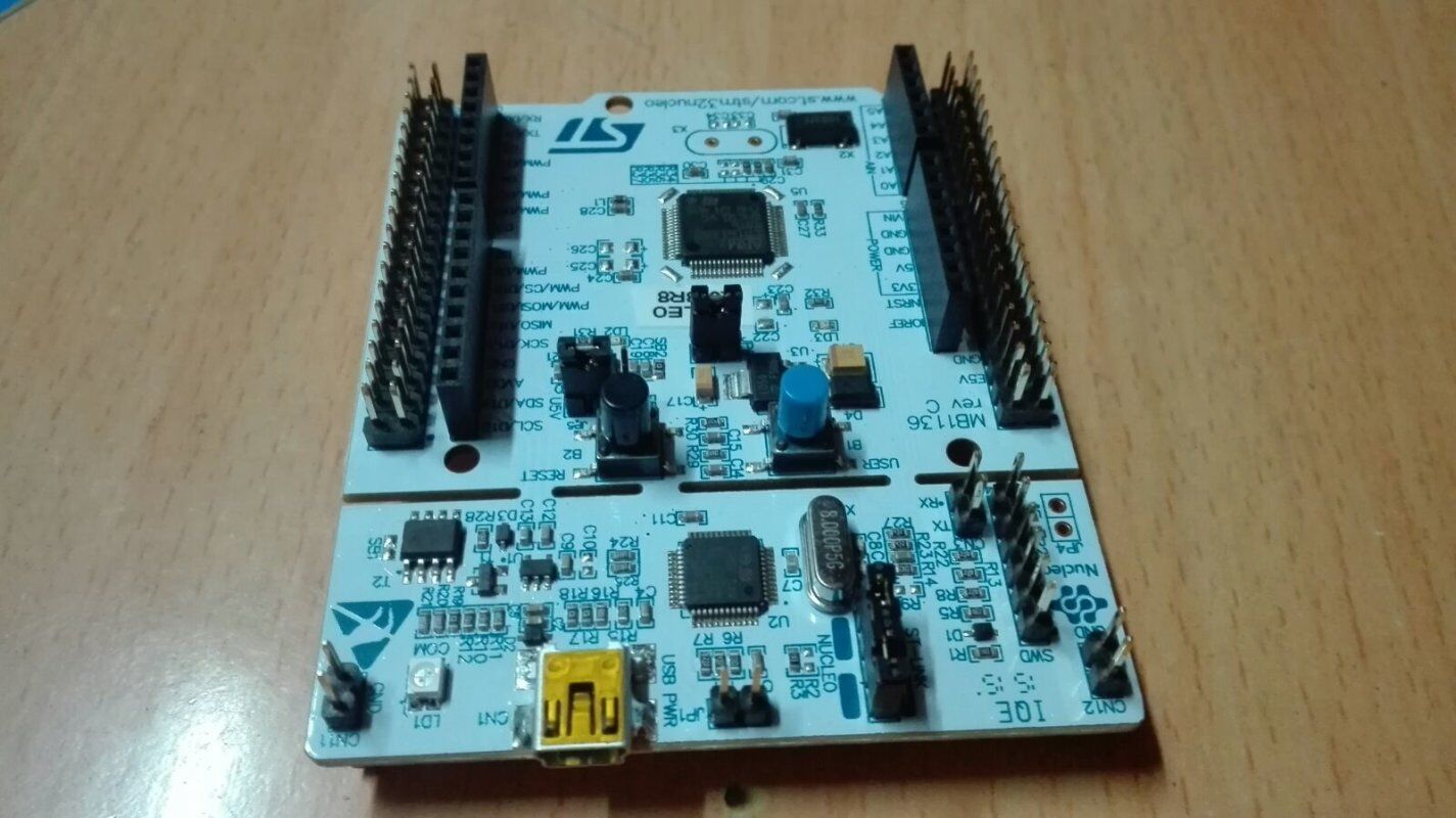
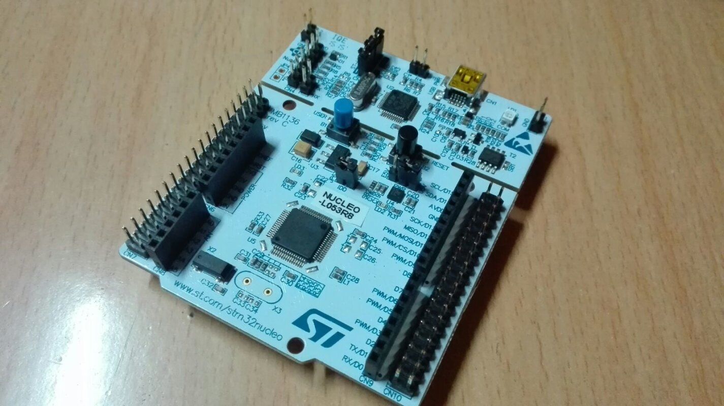
开发方式
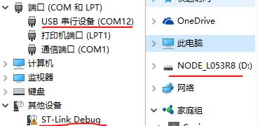
nucleo(下称核板)开发板果然与众不同,通过usb链接PC后,出现三个设备,从上到下分别是串口、储存设备、link Debug设备,最后一个设备需要驱动才能使用。
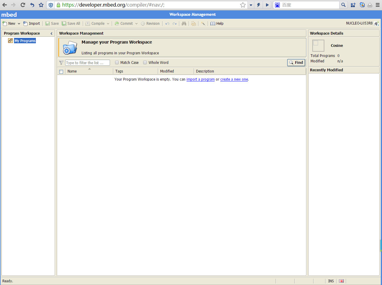
那么集成开发环境呢,找了一圈才知道,原来就是磁盘里那个网页文件跳转后的STM Mbed平台。

打开网页能自动进入平台,注册新账号即可添加开发板到你的账号里,然后就能使用这个在线的集成开发环境了。
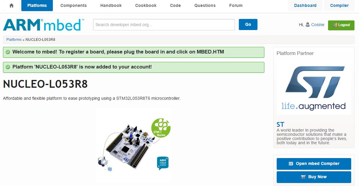
右上角的"Compiler"进入IDE
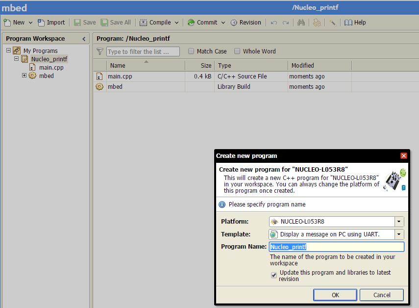
这时可以创建新程序,还有一些模板可以选择
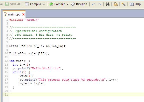
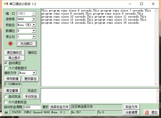
这时点 编译 就能编译出.bin可执行文件,然后下载到 核板 的磁盘就能自动运行
真的很容易上手,感觉和Arduino有异曲同工之妙
了解核板
前面提到了Link Debug,这是什么功能呢。
于是我在这里找到了很多核板的参数:
https://developer.mbed.org/platforms/ST-Nucleo-L053R8/
下面是摘抄:
核板特点
UART 共用到在 D0、 D1 脚
These pins are shared with the PC Serial connection via STLink. If you need to use these pins independently, see this page:https://developer.mbed.org/teams/ST/wiki/Use-of-D0D1-Arduino-pins
引脚使用提示
Only the labels written in blue/white or green/white (i.e. PA_4, PB_5, A0, D14, LED1...) must be used in your code. The other labels are given as information (alternate-functions, power pins, ...). You can also use these additional labels:
SERIAL_TX=PA_2  I2C_SCL=PB_8  SPI_MOSI=PA_7  PWM_OUT=PB_3
SERIAL_RX=PA_3  I2C_SDA=PB_9  SPI_MISO=PA_6
                              SPI_SCK =PA_5
                              SPI_CS  =PB_6
扩展板使用提示
先从移植Arduino小制作开始更吧,我发现我的程序非常多,如果移植每个程序都做大量查找替换操作,那会非常繁琐。

还好C语言很灵活并且有强大的宏功能。
这是mbed上的BLink程序:

而这是Arduino Blink:

我先创建了空模板项目

函数实现:
已有函数


把Arduino程序复制过来加个头尾

头实现


其中pinMode是假函数,这样就能在移植时做最少修改了,加了头尾和宏定义引脚即可。
Delay函数也可以用宏替换实现,但是考虑到还有wait()函数,可以再定义个float参数的delay(float sec),所以我用函数实现。
编译运行通过。。。。。
Blink过后,我移植了一个显示温度湿度的LED屏小制作。

main.cpp
#include "mbed.h"
#include "Arduino.h"
Serial serial(USBTX, USBRX);


#include "LED_Array.h"
#include "Dht11.h"
Dht11 DHT11(D7);

unsigned char RedData[70] = { 0 };
unsigned char GreenData[70] = { 0 };
unsigned char BlueData[70] = { 0 };
unsigned char humb = 0;
unsigned char temp = 0;
unsigned char old_humb = 0;
unsigned char old_temp = 0;
unsigned char count = 0;


void ColouredPos(int pos, char color, char value)
{
    boolean R = color & 0x01;
    boolean G = color & 0x02;
    boolean B = color & 0x04;
    //根据色权转二进制以对指定位置制定色板上色
    if (R)
        DotToData(RedData, pos, value);
    else
        DotToData(RedData, pos, 0x10);

    if (G)
        DotToData(GreenData, pos, value);
    else
        DotToData(GreenData, pos, 0x10);

    if (B)
        DotToData(BlueData, pos, value);
    else
        DotToData(BlueData, pos, 0x10);
}

void ColouredPos(int pos, char color)
{
    //模板套用简化
    char value = 12;
    switch (pos) {
        case 0:
            value = 12;
            break;
        case 5:
            value = 13;
            break;
        case 2:
            value = 14;
            break;
        case 7:
            value = 15;
            break;
    }
    ColouredPos(pos, color, value);
}

void ColouredValue(int value, char color,  boolean temp)
{
    unsigned char LeftPos = 1;
    unsigned char RightPos = 4;
    if (!temp) {
        LeftPos = 3;
        RightPos = 6;
    }
    ColouredPos(LeftPos, color, value / 10 % 10);
    ColouredPos(RightPos, color, value % 10);
}

void testOne()
{
    for (int i = 0; i < 8; i++) {
        ColouredPos(0, i);
        ColouredPos(5, i);
        ColouredPos(2, i);
        ColouredPos(7, i);
        ColouredValue(9, i, 1);
        ColouredValue(51, i, 0);
        for (int n = 80; n > 1; n--) {
            Write_LED_Array(RedData, RED);
            Write_LED_Array(GreenData, GREEN);
            Write_LED_Array(BlueData, BLUE);
        }
    }
}

void testTwo()
{
    ColouredPos(0, RED);
    ColouredPos(5, YELLO);
    ColouredPos(2, BLUE);
    ColouredPos(7, YELLO);
    ColouredValue(16, CYAN, 1);
    ColouredValue(51, GREEN, 0);
    while (1) {
        Write_LED_Array(RedData, RED);
        Write_LED_Array(GreenData, GREEN);
        Write_LED_Array(BlueData, BLUE);
    }
}

void getDHT11()
{
    count++;
    int chk;
    do {
        chk = DHT11.read();
    } while (chk == DHTLIB_OK);

    if (count == 100) {
        count = 0;
        old_humb = humb;
        old_temp = temp;
    }

    humb = DHT11.getHumidity();
    temp = DHT11.getFahrenheit();
    if (humb >= old_humb)
        ColouredValue(humb, GREEN, 0);
    else
        ColouredValue(humb, CYAN, 0);
    if (temp >= old_temp)
        ColouredValue(temp, GREEN, 1);
    else
        ColouredValue(temp, CYAN, 1);


    serial.printf("Humidity (%%): %d\n",humb);
    serial.printf("Temperature (oC): %d\n\n",temp);
//    Serial.print("Humidity (%): ");
//    Serial.println(humb, DEC);
//    Serial.print("Temperature (oC): ");
//    Serial.println(temp, DEC);
//    Serial.println();
}

void setup()
{
    Init_LED_Array();
    //Serial.begin(9600);
    ColouredPos(0, BLUE);
    ColouredPos(5, BLUE);
    ColouredPos(2, BLUE);
    ColouredPos(7, BLUE);
    ColouredValue(0, CYAN, 1);
    ColouredValue(0, GREEN, 0);
    //t.every(10000, getDHT11);
}

void loop()
{
    //t.update();
    getDHT11();
    for(long i=0; i<100; i++) {
        Write_LED_Array(GreenData, GREEN);
        Write_LED_Array(BlueData, BLUE);
    }
    serial.printf("LOOP!!!\n");
}


int main()
{
    setup();
    while(1) {
        loop();
    }
}
LED_Array.h & cpp
#ifndef LED_Array_H
#define LED_Array_H
#define HaltSize 1
#define LIGHT 160
#define     R0       D2
#define     R1       D3
#define     G0       D8
#define     G1       D9
#define     L0       D11
#define     L1       D12
#define     STB         A4//RCLK STCP//STB 正脉冲(几十纳秒)更新输出
#define     CLK         A5//SCLK SHCP//CLK 上升沿位移输入数据
#define     EN         D13//OE  低电平开启
#define     RowA        A0
#define     RowB        A1
#define     RowC        A2
#define     RowD        A3
/*色权
 * 基本:
 * 0——无色
 * 1——红色
 * 2——绿色
 * 4——蓝色
 * 扩展:
 * 3——红绿:黄
 * 5——红蓝:桃
 * 6——蓝绿:青、
 * 7——白
 */
#define     OFF        0
#define     RED        1
#define     GREEN        2
#define     BLUE        4
#define     PINK        5
#define     YELLO        3
#define     CYAN        6
#define     WHITE        7


const unsigned char Dot[] =
{
  0x00, 0xFE, 0xC6, 0xCE, 0xD6, 0xE6, 0xC6, 0xFE,//G:\WPad\0.BMP0
  0x00, 0x38, 0x18, 0x18, 0x18, 0x18, 0x18, 0x3C,//G:\WPad\1.BMP0
  0x00, 0xFE, 0x06, 0x06, 0xFE, 0xC0, 0xC0, 0xFE,//G:\WPad\2.BMP0
  0x00, 0xFE, 0x06, 0x06, 0xFE, 0x06, 0x06, 0xFE,//G:\WPad\3.BMP0
  0x00, 0xC6, 0xC6, 0xC6, 0xFE, 0x06, 0x06, 0x06,//G:\WPad\4.BMP0
  0x00, 0xFE, 0xC0, 0xC0, 0xFE, 0x06, 0x06, 0xFE,//G:\WPad\5.BMP0
  0x00, 0xFE, 0xC0, 0xC0, 0xFE, 0xC6, 0xC6, 0xFE,//G:\WPad\6.BMP0
  0x00, 0xFE, 0x06, 0x0C, 0x18, 0x30, 0x60, 0x60,//G:\WPad\7.BMP0
  0x00, 0xFE, 0xC6, 0xC6, 0xFE, 0xC6, 0xC6, 0xFE,//G:\WPad\8.BMP0
  0x00, 0xFE, 0xC6, 0xC6, 0xFE, 0x06, 0x06, 0xFE,//G:\WPad\9.BMP0
  0x00, 0x10, 0x38, 0x7C, 0xFE, 0x00, 0x00, 0x00,//G:\WPad\up.BMP0
  0x00, 0x00, 0x00, 0xFE, 0x7C, 0x38, 0x10, 0x00,//G:\WPad\down.BMP0
  0x00, 0x18, 0x24, 0x24, 0x34, 0x34, 0x34, 0x18,//G:\WPad\temp2.BMP0
  0x00, 0xE6, 0xA8, 0xE8, 0x08, 0x08, 0x08, 0x06,//G:\WPad\temp.BMP0
  0x00, 0x10, 0x10, 0x38, 0x7C, 0x7C, 0x7C, 0x38,//G:\WPad\humb2.BMP0
  0x00, 0xE2, 0xA4, 0xE8, 0x10, 0x2E, 0x4A, 0x8E,//G:\WPad\humb.BMP0
  0x00, 0x00, 0x00, 0x00, 0x00, 0x00, 0x00, 0x00,//0x00
};//字模

void Write_595(unsigned char Data, PinName PIN_595);
//this is the base driver of 74HC595
void Init_LED_Array(void);
//put this function into setup()
void Display();
//you can modify this function to display contents that you what to show
void Write_LED_Array(unsigned char *Data, unsigned char color);
//this is the base driver of LED array
void DotToData(unsigned char *Data, unsigned char Pos, unsigned char Draw);
//将字模放到数组中指定屏幕区域
#endif
#include "mbed.h"
#include "Arduino.h"

#include "LED_Array.h"
void Display()//you can modify this function to display contents that you what to show
{
    //  unsigned char i;
    //  for (i = 80; i > 1; i--)
    //  {
    //    Write_LED_Array(0, &cod1[0x0000], R0); //Write_LED_Array(pos,data,color);
    //    Write_LED_Array(1, &cod1[64], R1);
    //  }
    //  for (i = 80; i > 1; i--)
    //  {
    //    Write_LED_Array(0, &cod1[128], R0); //Write_LED_Array(pos,data,color);
    //    Write_LED_Array(1, &cod1[192], R1);
    //  }

}
void Init_LED_Array(void)//put this function into setup()
{

    pinMode(R0, OUTPUT);
    pinMode(R1, OUTPUT);
    pinMode(G0, OUTPUT);
    pinMode(G1, OUTPUT);
    pinMode(L0, OUTPUT);
    pinMode(L1, OUTPUT);
    digitalWrite(R0, LOW);
    digitalWrite(R1, LOW);
    digitalWrite(G0, LOW);
    digitalWrite(G1, LOW);
    digitalWrite(L0, LOW);
    digitalWrite(L1, LOW);

    pinMode(STB, OUTPUT);
    pinMode(CLK, OUTPUT);
    pinMode(EN, OUTPUT);

    pinMode(RowA, OUTPUT);
    pinMode(RowB, OUTPUT);
    pinMode(RowC, OUTPUT);
    pinMode(RowD, OUTPUT);


    digitalWrite(EN, HIGH);
    digitalWrite(STB, LOW);

}
void Write_595(unsigned char Data, PinName PIN_595) //this is the base driver of 74HC595
{
    digitalWrite(CLK, LOW);
    digitalWrite(PIN_595, (Data & 0x80));
    digitalWrite(CLK, HIGH);
    digitalWrite(CLK, LOW);
    digitalWrite(PIN_595, (Data & 0x40));
    digitalWrite(CLK, HIGH);
    digitalWrite(CLK, LOW);
    digitalWrite(PIN_595, (Data & 0x20));
    digitalWrite(CLK, HIGH);
    digitalWrite(CLK, LOW);
    digitalWrite(PIN_595, (Data & 0x10));
    digitalWrite(CLK, HIGH);
    digitalWrite(CLK, LOW);
    digitalWrite(PIN_595, (Data & 0x08));
    digitalWrite(CLK, HIGH);
    digitalWrite(CLK, LOW);
    digitalWrite(PIN_595, (Data & 0x04));
    digitalWrite(CLK, HIGH);
    digitalWrite(CLK, LOW);
    digitalWrite(PIN_595, (Data & 0x02));
    digitalWrite(CLK, HIGH);
    digitalWrite(CLK, LOW);
    digitalWrite(PIN_595, (Data & 0x01));
    digitalWrite(CLK, HIGH);
}
void Write_LED_Array(unsigned char *Data, unsigned char color) //this is the base driver of LED array
{
    unsigned char *pTemp;
    unsigned char row;
    PinName DataPin = R0;
    PinName DataPin2 = R1;

    if (color == GREEN) {
        DataPin = G0;
        DataPin2 = G1;
    } else if (color == BLUE) {
        DataPin = L0;
        DataPin2 = L1;
    }

    for (row = 0; row < 16; row++) {
        digitalWrite(EN, HIGH);

        pTemp = (Data + row * 2);
        if (HaltSize && row >= 8) {
            Write_595(*pTemp, DataPin2);
            Write_595(*(pTemp + 1), DataPin2);
            Write_595(*(pTemp += 32), DataPin2);
            Write_595(*(pTemp + 1), DataPin2);
        } else {
            Write_595(*pTemp, DataPin);
            Write_595(*(pTemp + 1), DataPin);
            Write_595(*(pTemp += 32), DataPin);
            Write_595(*(pTemp + 1), DataPin);
        }

        digitalWrite(STB, HIGH);
        delayMicroseconds(1);
        digitalWrite(STB, LOW);
        delayMicroseconds(1);

        digitalWrite(RowA, (row & 0x01)); //set display line
        digitalWrite(RowB, (row & 0x02)); //Sequential scan
        digitalWrite(RowC, (row & 0x04));
        if (!HaltSize)
            digitalWrite(RowD, (row & 0x08));

        digitalWrite(EN, LOW);
        delayMicroseconds(LIGHT);

    }
}

void DotToData(unsigned char *Data, unsigned char Pos, unsigned char Draw)
{
    //将字模放到数组中指定屏幕区域
    /*区域
     Pos:
     0  1 4 5
     2  3 6 7
     */
    const unsigned char *p = &Dot[Draw * 8];//字模编号取得指针
    //区域处理
    char n = Pos / 2;
    Pos = Pos % 2;
    for (char i = n * 16; i < (n + 1) * 16; i += 2) {
        if (Pos)
            Data[i + 1] = *(p++);
        else
            Data[i] = *(p++);
    }
}
Arduino.h & cpp
#ifndef Arduino_H
#define Arduino_H
#define HIGH 1
#define LOW 0
#define pinMode(PinName,Mode)
#define digitalWrite(PinName,Value) DigitalOut(PinName,Value)
#define digitalRead(PinName,Value) DigitalIn(PinName,Value)
#define delayMicroseconds(us) wait_us(us);
typedef bool boolean;
//#define print
void delay(int ms);
#endif
#include "mbed.h"
#include "Arduino.h"
void delay(int ms)
{
    wait_ms(ms);
}
 我要赚赏金打赏帖 我要赚赏金打赏帖 |
|
|---|---|
| 片外存储Flash使用方法(Arduino IDE环境)被打赏¥22元 | |
| 三分钟快速上手ESP-NOW(ArduinoIDE环境)被打赏¥23元 | |
| 【S32K3XX】LPSPI参数配置说明被打赏¥21元 | |
| 在WT9932C61-TINY上实现超声波测距被打赏¥22元 | |
| 基于WT9932C61-TINY的环境构建及OLED屏驱动测试被打赏¥20元 | |
| 【S32K3XX】Core-to-Core 中断使用被打赏¥21元 | |
| 「AI编程记录--含源码」用一晚上的时间写一个esp32的示波器被打赏¥19元 | |
| STM32C0116DK开发探索记(3)被打赏¥30元 | |
| STM32C0116DK开发探索记(2)被打赏¥24元 | |
| STM32C0116DK开发探索记(1)被打赏¥29元 | |
 STM32
STM32 MCU
MCU 通讯及无线技术
 物联网技术
物联网技术 电子DIY
电子DIY 板卡试用
板卡试用 基础知识
基础知识 软件与操作系统
 我爱生活
我爱生活 小e食堂
小e食堂

