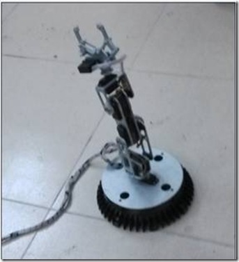
机械手为6路舵机,在控制机械手的同时要了解舵机的工作原理。
舵机工作原理
标准的舵机有3条导线,分别为电源线,地线,控制线。
舵机的控制信号为周期是 20ms 的脉宽调制( PWM )信号,其中脉冲宽度从0.5ms-2.5ms ,相对应舵盘的位置为 0 - 180 度,呈线性变化。也就是说 , 给它提供一定的脉宽 , 它的输出轴就会保持在一个相对应的角度上 , 无论外界转矩怎样改变 , 直到给它提供一个另外宽度的脉冲信号 , 它才会改变输出角度到新的对应的位置上 。 舵机内部有一个基准电路 , 产生周期 20ms , 宽度 1.5ms 的基准信号 , 有一个比较器 , 将外加信号与基准信号相比较 , 判断出方向和大小 , 从而产生电机的转动信号 。由此可见,舵机是一种位置伺服的驱动器,转动范围不能超过 180 度 ,适用于那些需要角度不断变化并可以保持的驱动当中 。
因此,我们只需要控制好pwm波就可以对每路舵机进行控制,这里先简单介绍一下用dsp来控制舵机的方法。在dsp中只需要用pwm模块,产生一个周期为20ms的占空比可调的pwm波(根据CMPA来调。)然后,上位机发送CMPA的值给dsp就可以了。
以前我还没有在FPGA中来对舵机进行控制,但是用FPGA来实现也是简单的,6路舵机的控制框图如下:
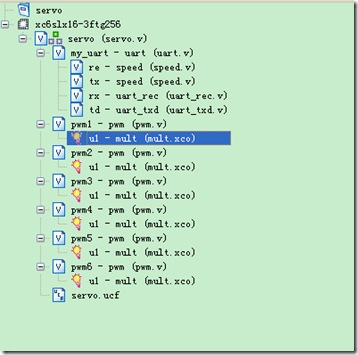
工程文件视图:6个pwm模块是一样的。
实现6字节uart接收和发送,verilog代码如下:
module uart_rec(clk,rst_n,clk_bps,rxd,bps_start,rec_data,rec_ready); input clk,rst_n,clk_bps,rxd; output bps_start; output rec_ready; reg rec_ready; reg [47:0]rec_temp; output [47:0]rec_data; reg [47:0]rec_data_r; reg rs232_rx0,rs232_rx1/*,rs232_rx2,rs232_rx3*/; reg bps_start_r; reg [7:0]num;//鎺ユ敹鏁版嵁浣嶆暟 wire neg_start; always @(posedge clk or negedge rst_n) begin if(!rst_n) begin rs232_rx0 = 1'b0; rs232_rx1 = 1'b0; // rs232_rx2 <= 1'b0; // rs232_rx3 <= 1'b0; end else begin //rs232_rx0<=rxd; rs232_rx1=rs232_rx0; rs232_rx0=rxd; // rs232_rx2<=rs232_rx1; //rs232_rx3<=rs232_rx2; end end assign neg_start=/*rs232_rx3 & rs232_rx2 &*/ rs232_rx1 & ~rs232_rx0; always @(posedge clk or negedge rst_n) begin if(!rst_n) begin rec_ready<=0;bps_start_r<=0;end else if(neg_start) begin rec_ready<=1;bps_start_r<=1; end//鍑嗗鎺ユ敹鏁版嵁 else if(num==60) begin bps_start_r<=0; rec_ready<=0; end end assign bps_start=bps_start_r; always @(posedge clk or negedge rst_n) begin if(!rst_n) begin num<=0; rec_temp<=0; // rec_data_r<=0; end else if(clk_bps) begin num<=num+1; case(num) 8'd1: rec_temp[0]<=rxd; 8'd2: rec_temp[1]<=rxd; 8'd3: rec_temp[2]<=rxd; 8'd4: rec_temp[3]<=rxd; 8'd5: rec_temp[4]<=rxd; 8'd6: rec_temp[5]<=rxd; 8'd7: rec_temp[6]<=rxd; 8'd8: rec_temp[7]<=rxd; 8'd11: rec_temp[8]<=rxd; 8'd12: rec_temp[9]<=rxd; 8'd13: rec_temp[10]<=rxd; 8'd14: rec_temp[11]<=rxd; 8'd15: rec_temp[12]<=rxd; 8'd16: rec_temp[13]<=rxd; 8'd17: rec_temp[14]<=rxd; 8'd18: rec_temp[15]<=rxd; 8'd21: rec_temp[16]<=rxd; 8'd22: rec_temp[17]<=rxd; 8'd23: rec_temp[18]<=rxd; 8'd24: rec_temp[19]<=rxd; 8'd25: rec_temp[20]<=rxd; 8'd26: rec_temp[21]<=rxd; 8'd27: rec_temp[22]<=rxd; 8'd28: rec_temp[23]<=rxd; 8'd31: rec_temp[24]<=rxd; 8'd32: rec_temp[25]<=rxd; 8'd33: rec_temp[26]<=rxd; 8'd34: rec_temp[27]<=rxd; 8'd35: rec_temp[28]<=rxd; 8'd36: rec_temp[29]<=rxd; 8'd37: rec_temp[30]<=rxd; 8'd38: rec_temp[31]<=rxd; 8'd41: rec_temp[32]<=rxd; 8'd42: rec_temp[33]<=rxd; 8'd43: rec_temp[34]<=rxd; 8'd44: rec_temp[35]<=rxd; 8'd45: rec_temp[36]<=rxd; 8'd46: rec_temp[37]<=rxd; 8'd47: rec_temp[38]<=rxd; 8'd48: rec_temp[39]<=rxd; 8'd51: rec_temp[40]<=rxd; 8'd52: rec_temp[41]<=rxd; 8'd53: rec_temp[42]<=rxd; 8'd54: rec_temp[43]<=rxd; 8'd55: rec_temp[44]<=rxd; 8'd56: rec_temp[45]<=rxd; 8'd57: rec_temp[46]<=rxd; 8'd58: rec_temp[47]<=rxd; default: ; endcase end else if(num==60) begin num<=0; rec_data_r<=rec_temp; end end assign rec_data=rec_data_r; endmodule module uart_txd(clk,rst_n,clk_bps,bps_start,rec_ready,rec_data,txd); input clk,rst_n,clk_bps,rec_ready; input [47:0]rec_data; output bps_start,txd; reg [47:0]txd_temp; reg bps_start_r; reg txd_r; reg [7:0]num; //reg en; wire neg_int;//鏄惁妫€鏌ュ埌int鐨勪笅闄嶆部 reg int0,int1; always @(posedge clk or negedge rst_n) begin if(!rst_n) begin int0<=0; int1<=0; // int2<=0; end else begin int0<=rec_ready; int1<=int0; // int2<=int1; end end assign neg_int=int1 & ~int0;//涓轰竴琛ㄧず涓嬮檷娌鍒颁簡 always @(posedge clk or negedge rst_n) begin if(!rst_n) begin bps_start_r<=1'b0;/*en<=0; txd_temp<=0;*/end else if(neg_int) begin /*en<=1; */bps_start_r<=1;txd_temp<=rec_data;end else if(num==60) begin /*en<=0;*/bps_start_r<=0;end end always @(posedge clk or negedge rst_n) begin if(!rst_n) begin num<=0; txd_r<=1; end else //if(en) if(clk_bps) begin num<=num+1; case(num) 8'd0: txd_r<=0; 8'd1: txd_r<=txd_temp[0]; 8'd2: txd_r<=txd_temp[1]; 8'd3: txd_r<=txd_temp[2]; 8'd4: txd_r<=txd_temp[3]; 8'd5: txd_r<=txd_temp[4]; 8'd6: txd_r<=txd_temp[5]; 8'd7: txd_r<=txd_temp[6]; 8'd8: txd_r<=txd_temp[7]; 8'd9: txd_r<=1; 8'd10: txd_r<=0; 8'd11: txd_r<=txd_temp[8]; 8'd12: txd_r<=txd_temp[9]; 8'd13: txd_r<=txd_temp[10]; 8'd14: txd_r<=txd_temp[11]; 8'd15: txd_r<=txd_temp[12]; 8'd16: txd_r<=txd_temp[13]; 8'd17: txd_r<=txd_temp[14]; 8'd18: txd_r<=txd_temp[15]; 8'd19: txd_r<=1; 8'd20: txd_r<=0; 8'd21: txd_r<=txd_temp[16]; 8'd22: txd_r<=txd_temp[17]; 8'd23: txd_r<=txd_temp[18]; 8'd24: txd_r<=txd_temp[19]; 8'd25: txd_r<=txd_temp[20]; 8'd26: txd_r<=txd_temp[21]; 8'd27: txd_r<=txd_temp[22]; 8'd28: txd_r<=txd_temp[23]; 8'd29: txd_r<=1; 8'd30: txd_r<=0; 8'd31: txd_r<=txd_temp[24]; 8'd32: txd_r<=txd_temp[25]; 8'd33: txd_r<=txd_temp[26]; 8'd34: txd_r<=txd_temp[27]; 8'd35: txd_r<=txd_temp[28]; 8'd36: txd_r<=txd_temp[29]; 8'd37: txd_r<=txd_temp[30]; 8'd38: txd_r<=txd_temp[31]; 8'd39: txd_r<=1; 8'd40: txd_r<=0; 8'd41: txd_r<=txd_temp[32]; 8'd42: txd_r<=txd_temp[33]; 8'd43: txd_r<=txd_temp[34]; 8'd44: txd_r<=txd_temp[35]; 8'd45: txd_r<=txd_temp[36]; 8'd46: txd_r<=txd_temp[37]; 8'd47: txd_r<=txd_temp[38]; 8'd48: txd_r<=txd_temp[39]; 8'd49: txd_r<=1; 8'd50: txd_r<=0; 8'd51: txd_r<=txd_temp[40]; 8'd52: txd_r<=txd_temp[41]; 8'd53: txd_r<=txd_temp[42]; 8'd54: txd_r<=txd_temp[43]; 8'd55: txd_r<=txd_temp[44]; 8'd56: txd_r<=txd_temp[45]; 8'd57: txd_r<=txd_temp[46]; 8'd58: txd_r<=txd_temp[47]; 8'd59: txd_r<=1; default: ; endcase end else if(num==8'd60) begin num<=0; txd_r<=1; end end assign bps_start=bps_start_r; assign txd=txd_r; endmodule
计算pwm:
0.5ms对应 25000个clk
2.5ms对应 125000个clk
假定1.5ms的时候在中间,为了好计算,这个时候认为是90,即0.5ms认为是0度,2.5为180度。
将输入的角度(串口接收的数据)换算成cnt(多少个clk) cnt=25000+555x
这里肯定就要用到乘法器了。用到了ip核了,这里有倒腾了几个小时,这里记录下一些教训吧。对于xilinx的新手要使用ip核的话,在ip核那里有datesheet,要正确使用的话需要阅读手册。
除了这个之外,需要注意的是选择好output的宽度,我之前没设置好这个宽度,数据就是不对,后面通过Isim的仿真才发现了这个问题,这也反映了仿真的重要性,至于调试利器chipscope的话,我这电脑实在是太慢,不到最后,不采用了。
Pwm模块的verilog设计:
`timescale 1ns / 1ps
//////////////////////////////////////////////////////////////////////////////////
// Company:
// Engineer:
//
// Create Date:    16:32:07 04/08/2014
// Design Name:
// Module Name:    pwm
// Project Name:
// Target Devices:
// Tool versions:
// Description:
//
// Dependencies:
//
// Revision:
// Revision 0.01 - File Created
// Additional Comments:
//
//////////////////////////////////////////////////////////////////////////////////
module pwm(
    input clk,
    input rst_n,
    input [7:0] angle,
    output pwm
	// output [19:0]cnt
    );

//产生周期为20ms,时钟周期为20ns
reg [19:0]cnt_period;
always @(posedge clk)
begin
	if(!rst_n)
		cnt_period<=0;
	else if(cnt_period==20'd1000000)
				cnt_period<=0;
			else
				cnt_period<=cnt_period+1'b1;
end
/*
0.5ms对应   25000个clk
2.5ms对应  125000个clk
假定1.5ms的时候在中间,为了好计算,这个时候认为是90,即0.5ms认为是0度,2.5为180度
将输入的角度换算成cnt(多少个clk) cnt=25000+555x
*/
wire [19:0]cnt;
wire [19:0]mut_temp;
wire [9:0]a=10'd555;
//wire [7:0]b=8'd90;
assign cnt=25000+mut_temp;
assign pwm=(cnt_period<=cnt)?1:0;

wire sclr,ce,bypass;
assign sclr=0;
assign ce=1;
assign bypass=1;
mult u1 (
  .clk(clk), // input clk
  .ce(ce), // input ce
  .sclr(sclr), // input sclr
  .bypass(bypass), // input bypass
  .a(a), // input [9 : 0] a
  .b(angle), // input [7 : 0] b
  .s(mut_temp) // output [17 : 0] s
);
endmodule
经过示波器测量,发现信号没有问题的话,接上舵机,试试效果。
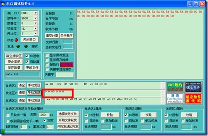
注意一次发送6个字节,90度换算成16进制就是5A
结果却没有看到想要的结果,发现有一个舵机瘫在那了,才记起来了,有一个舵机是坏的,正好有机会换一个了,哈哈。不过不影响测试,试试其它的。


 我要赚赏金
我要赚赏金

