

【LAUNCHXL-F280049C】①愉快地开箱及苦涩地点灯-电子产品世界论坛
接上回点灯成功后,就开始琢磨一款单片机最基础的串口输出,毕竟Hello world!是必不可少的仪式感。
依然是 New Project,选择型号LAUNCHXL-F280049C,就出来很多官方例程。
寻找到一款名为“baud_tune_via_uart”的例程,通过波特率调节串口。

拿到程序后,先研究下baud_tune_via_uart.c主函数。
参照第一篇帖子,先在.sysconfig文件设置好串口硬件。
设置波特率为9600,8,1,N

再拉到下方设置PinMux引脚。
我们看下LAUNCHXL-F280049C电路图。
电路图LAUNCHXL-F280049C Schematic.pdf

如果要使用调试器(XDS)的串口,就要设置为GPIO28 GPIO29为串口功能。并且确保板子上的S6 S8开关位置正确(默认即可)

S8调至上方(28/29),S6调至下方(UART)

void main(void){    stopCaptures = 0;
    //    // Initialize device clock and peripherals    //    Device_init();
    //    // Disable pin locks and enable internal pullups.    //    Device_initGPIO();
    //    // Initialize PIE and clear PIE registers. Disables CPU interrupts.    //    Interrupt_initModule();
    //    // Initialize the PIE vector table with pointers to the shell Interrupt    // Service Routines (ISR).    //    Interrupt_initVectorTable();
    //    // Board Initialization    //    Board_init();
    SCI_enableTxModule(mySCI0_BASE);    //    // Enable Global Interrupt (INTM) and Real time interrupt (DBGM)    //    EINT;    ERTM;

            //            // Update the device's baud rate to match the measured baud rate            //            SCI_setBaud(mySCI0_BASE, DEVICE_LSPCLK_FREQ, 9600);
            //            // Wait for user to view the results in "Expressions" window            //                   //            // (OPTIONAL) Continuously send data to SCITX once tuning            // is complete for external observation (by logic analyzer or            // scope)            //            unsigned char *msg;                           msg = "Hello world!\0";                SCI_writeCharArray(SCIA_BASE, (uint16_t*)msg, 12);
            //            // If continuing, reset the array iterator and unlock the ISR for            // new captures            //            //sampleArrIter=0;            stopCaptures=0;          }
void main(void){ stopCaptures = 0;
// // Initialize device clock and peripherals //
Device_init();
// // Disable pin locks and enable internal pullups. //
Device_initGPIO();
// // Initialize PIE and clear PIE registers. Disables CPU interrupts. //
Interrupt_initModule();
// // Initialize the PIE vector table with pointers to the shell Interrupt // Service Routines (ISR). // Interrupt_initVectorTable();
// // Board Initialization //
Board_init();
SCI_enableTxModule(mySCI0_BASE); // // Enable Global Interrupt (INTM) and Real time interrupt (DBGM) //
EINT; ERTM;
// // Update the device's baud rate to match the measured baud rate //
SCI_setBaud(mySCI0_BASE, DEVICE_LSPCLK_FREQ, 9600);
// // Wait for user to view the results in "Expressions" window // // // (OPTIONAL) Continuously send data to SCITX once tuning // is complete for external observation (by logic analyzer or // scope) // unsigned char *msg;
msg = "Hello world!\0";
SCI_writeCharArray(SCIA_BASE, (uint16_t*)msg, 12);
// // If continuing, reset the array iterator and unlock the ISR for // new captures // //sampleArrIter=0;
stopCaptures=0;
}
然后编译、调试。(具体方法见贴1)
需要补充的是,如果点击Debug,发现列表中没有本项目,就Add Configuration……

在随后的页面中:
launch.json文件
我们可以看到每个项目都有对用的几行描述。
可以copy现有内容,粘贴后把项目名称改成我们刚刚新建的工程名,再保存点Debug就出现在调试列表中。

运行后,串口调试助手就可以收到:Hello world!

通过本例,我们发现TI 的C2000编程也很简单(Driverlib),跟我们熟知的STM32的HAL(硬件抽象层)很像,也就是对硬件寄存器进行了包装,不需要我们记忆复杂的寄存器。
TI的官方介绍如下:

C2000Ware 支持通过多种方式访问外设寄存器:直接寄存器访问、驱动程序库 (DriverLib) 和位域。以下各节详细介绍了这些方式。DriverLib 是新一代 MCU 访问外设的优选模式。老一代 MCU 仅支持 Bitfield。但新一代 MCU 也支持 Bitfield,以实现兼容性和轻松迁移。
下面汇总了差异:
间接寄存器访问
寄存器地址分别定义 #define
用户必须计算位域掩码
不易于读取
例如 *CMPR1 = 0x1234;
位域头文件
头文件将所有寄存器定义为结构
位域直接访问
易于读取
例如 EPwm1Regs.CMPA.bit.CMPA = EPwm1Regs.TBPRD * duty;
DriverLib
DriverLib 执行低级寄存器操作
易于读取
抽象级别最高
例如 EPWM_setCounterCompareValue(EPWM1_BASE, EPWM_COUNTER_COMPARE_A, duty);
DriverLib
C2000 外设驱动程序库 (Driverlib) 是一组用于配置内存映射外设寄存器的低级驱动程序。它为所有外设提供驱动程序并提供对几乎所有功能的访问。driverlib 用 C 语言编写,由数据结构、宏定义和函数组成。C2000Ware 中提供了 driverlib 的完整源代码。
在顶层,driverlib 是基于器件整理的,每个器件下都有一个器件特定的 driverlib 文件夹。在此器件特定的 driverlib 文件夹中,提供了适用于该器件的外设驱动程序的源代码。
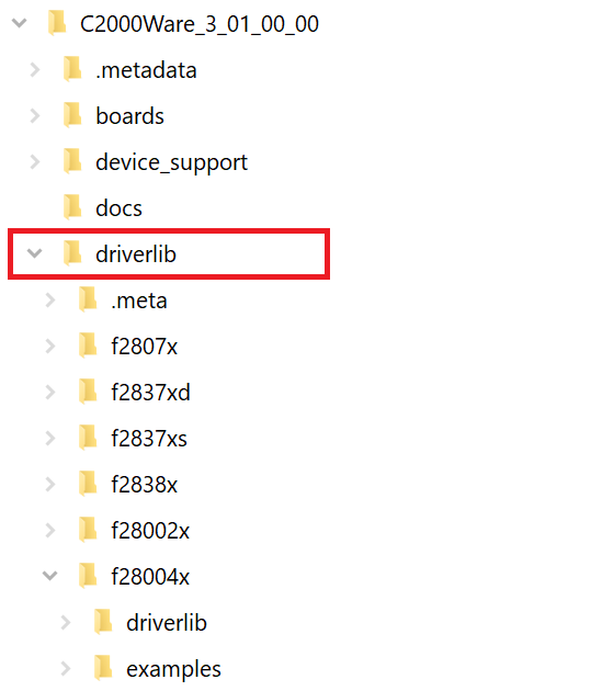
比如本项目:

我们想了解、掌握、使用串口,根本不用记忆寄存器,熟悉下sci.h文件即可,其中的函数任由我们调用。

本次分享就到这里。
 我要赚赏金
我要赚赏金 STM32
STM32 MCU
MCU 通讯及无线技术
 物联网技术
物联网技术 电子DIY
电子DIY 板卡试用
板卡试用 基础知识
基础知识 软件与操作系统
 我爱生活
我爱生活 小e食堂
小e食堂

