
7段数码管可以用来很方便地显示0-9的数字以及,因此在一些电子制作中经常被使用到。7段数码管顾名思义其实就是由7个LED组成,它们一般按照共阴或者共阳的方式连接在一起,既然原理上这么简单,那么用Arduino来驱动7段数码管的方式自然就不言而喻了:分别将7个LED的引脚连接到Arduino的7个引脚上,然后通过给相应引脚置高或者置低的方式来控制7段数码管上显示出不同的数字来。可是仔细想想你会发现,通常Arduino上只有12个可以使用的数字引脚,如果驱动一个7段数码管就需要占用7个引脚,那驱动两个更者更多7段数码管的话,Arduino的引脚数目马上就告急了!这个时候你就可以考虑我们这里介绍的这个4路7段数码管的电子积木模块了:-)
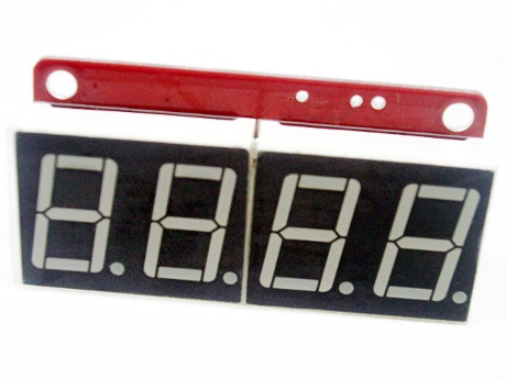
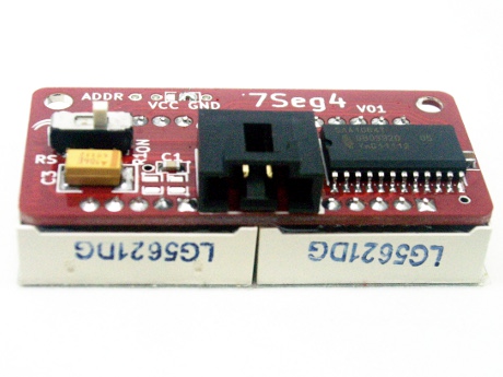
这个4位7段数码管的模块采用专用的驱动芯片来控制数码管的各个引脚,并且使用I2C总线与Arduino进行连接,也就是说我们只需要用两根数据线就可以用Arduino来控制这一数码管模块了:
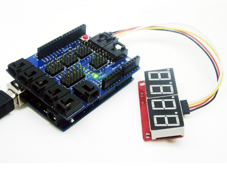
连接的方法很简单,只需要用专用的I2C连接线,将这一4位7段数码管与Arduino专用扩展板上的I2C端口连接起来就可以了:
同时注意将模块背面的RS开关设置到ON的位置,使能I2C引脚上的上拉电阻:
测试的时候可以使用如下的代码,该代码可以在数码管上循环显示0-9和a-f,同时还可以控制数码管上的小数点:
#include "Wire.h"  // enable I2C bus

//byte saa1064 = 0x70 >> 1; // define the I2C bus address for our SAA1064 (pin 1 to GND)
byte saa1064 = 0x76 >> 1; // define the I2C bus address for our SAA1064 (pin 1 to VCC)

int digits[16]={63, 6, 91, 79, 102, 109, 125,7, 127, 111, 119, 124, 57, 94, 121, 113};
// these are the byte representations of pins required to display each digit 0~9 then A~F

void setup()
{
  Wire.begin(); // start up I2C bus
  delay(500);
  initDisplay();
}

void initDisplay()
// turns on dynamic mode and adjusts segment current to 12mA
{
  Wire.beginTransmission(saa1064);
  Wire.send(B00000000); // this is the instruction byte. Zero means the next byte is the control byte
  Wire.send(B01000111); // control byte (dynamic mode on, digits 1+3 on, digits 2+4 on, 12mA segment current
  Wire.endTransmission();
}

void displayDigits()
// show all digits 0~9, A~F on all digits of display
{
  for (int z=0; z<16; z++)
  {
    Wire.beginTransmission(saa1064);
    Wire.send(1); // instruction byte - first digit to control is 1 (right hand side)
    Wire.send(digits[z]); // digit 1 (RHS)
    Wire.send(digits[z]); // digit 2
    Wire.send(digits[z]); // digit 3
    Wire.send(digits[z]); // digit 4 (LHS)
    Wire.endTransmission();
    delay(500);
  }

// now repeat but with decimal point

 for (int z=0; z<16; z++)
  {
    Wire.beginTransmission(saa1064);
    Wire.send(1); // instruction byte - first digit to control is 1 (right hand side)
    Wire.send(digits[z]+128); // digit 1 (RHS)
    Wire.send(digits[z]+128); // digit 2
    Wire.send(digits[z]+128); // digit 3
    Wire.send(digits[z]+128); // digit 4 (LHS)
    Wire.endTransmission();
    delay(500);
  }
}

void clearDisplay()
// clears all digits
{
  Wire.beginTransmission(saa1064);
  Wire.send(1); // instruction byte - first digit to control is 1 (right hand side)
  Wire.send(0); // digit 1 (RHS)
  Wire.send(0); // digit 2
  Wire.send(0); // digit 3
  Wire.send(0); // digit 4 (LHS)
  Wire.endTransmission();
}

void loop()
{
  displayDigits();
  clearDisplay();
  delay(1000);
}
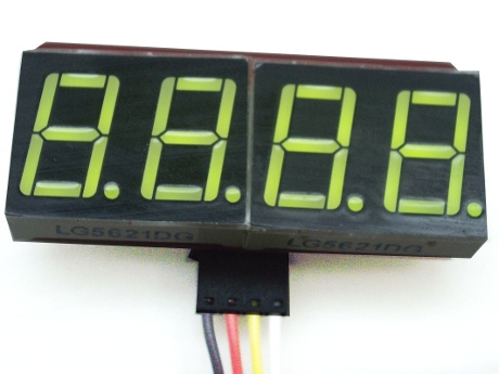
运行结果如下图所示:
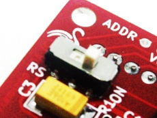
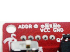
由于该模块使用的是I2C接口,因此实际上也允许同时接入多个数码管模块,但必须对模块的地址进行设置。在数码管模块的背面有一个ADDR跳线,正是进行这一地址位设置的:
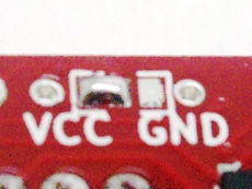
设置的办法是用铬铁将中间的引脚分别与VCC或者GND端连接起来,如果中间引脚与VCC连接时,相应的地址为0×76:
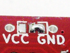
如果中间引脚与GND连接时,相应的地址为0×70:
这一模块在出厂时中间的引脚即不与VCC连接,也不与GND连接,此时的地址也是0×76。
 我要赚赏金
我要赚赏金 STM32
STM32 MCU
MCU 通讯及无线技术
 物联网技术
物联网技术 电子DIY
电子DIY 板卡试用
板卡试用 基础知识
基础知识 软件与操作系统
 我爱生活
我爱生活 小e食堂
小e食堂

