
随着智能手机的普遍,手机的功能变得越来越强大,在我们的日常生活中所扮演的角色也越来越重要,小到我们日常的饮食起居,大到工业、商业管理。我们可以回想一下自己手机是否已经代替了我们之前的闹钟,手机是否开始胚盘我们一起运动,手机是否可以实时查看一些我们的财经信息。这些答案都是肯定的,手机的智能化逐渐使得我们之前的很多工作都可以在移动中完成,不再受地域的限制,在接下来的内容中,风云物联网科技将手机与物联网结合起来,实现手机通过蓝牙与ZigBee无线传感网数据的通信。
本系统主要是通过手机通过蓝牙与蓝牙模块进行无线连接,蓝牙模块在通过穿行接口与ZigBee协调器链接,蓝牙主要充当一个无线中继,他的作用就是串口透传,整个系统主要由手机终端、蓝牙透传模块、ZigBee无线传感网三大部分组成,其中最核心的部分就是ZigBee无线传感网络这里不对ZigBee终端节点传感器驱动编程进行详细介绍,有需要了解的可以参考风云物联网科技倾力打造的ZigBee开发教程(打开网盘链接可以直接下载),这里着重对协调器与路由器的串口透传进行原理分析,并对源码进行解析。在具体的工程项目中我们可以根据自己的需要对数据进行相应格式的封装,下面通过一个简单例子和源码说明ZigBee串口透传的实现。
具体的实验原理为:首先由协调器建立网络,中断节点自动加入到该网络,加入成功后终端节点周期性的向协调器发送字符串“HLO I AM EndDevice”协调器接收到该字符串后,通过串口发送给手机,同时协调器通过无线回应终端节点发送字符串“HLO”给终端节点,具体通讯结构框图如图5-31所示:
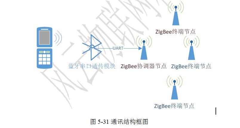
图5-31通讯结构框图
串口数据的无线传输协调器和终端节点程序流程图如图5-32a和5-32b所示:
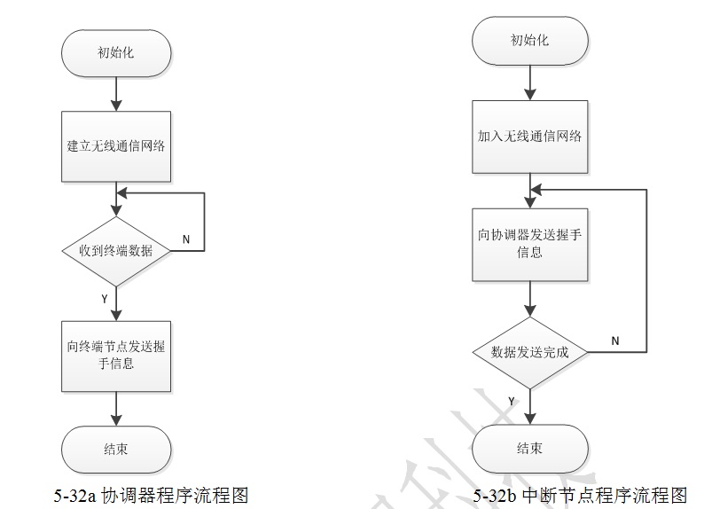
5-32a协调器程序流程图 5-32b中断节点程序流程图
在ZigBee的无线数据传输网络中有三种设备类型:协调器、路由器和终端节点,设备类型是由ZigBee协议栈中的不同选项决定,协调器负责网络的组建,维护以及终端节点的加入等任务。路由器负责数据包的路由选择,终端节点则负责数据的采集与无线发送。
以上程序实现了单个ZigBee开发板与电脑的串口通信,接下来我们实现两个开发板之间无线传输并将传输的无线数据通过串口发送到电脑。
接下来我们对实现源码进行分析:
协调器端源码:
#include "AF.h"
#include "ZDApp.h"
#include "ZDObject.h"
#include "ZDProfile.h"
#include "GenericApp.h"
#include "DebugTrace.h"
#if !defined( WIN32 )
#include "OnBoard.h"
#endif
/* HAL */
#include "hal_lcd.h"
#include "hal_led.h"
#include "hal_key.h"
#include "hal_uart.h"
/* RTOS */
#if defined( IAR_ARMCM3_LM )
#include "RTOS_App.h"
#endif
/*********************************************************************
* MACROS
*/
/*********************************************************************
* CONSTANTS
*/
/*********************************************************************
* TYPEDEFS
*/
/*********************************************************************
* GLOBAL VARIABLES
*/
// This list should be filled with Application specific Cluster IDs.
const cId_t GenericApp_ClusterList[GENERICAPP_MAX_CLUSTERS] =
{
GENERICAPP_CLUSTERID
};
const SimpleDescriptionFormat_t GenericApp_SimpleDesc =
{
GENERICAPP_ENDPOINT, // int Endpoint;
GENERICAPP_PROFID, // uint16 AppProfId[2];
GENERICAPP_DEVICEID, // uint16 AppDeviceId[2];
GENERICAPP_DEVICE_VERSION, // int AppDevVer:4;
GENERICAPP_FLAGS, // int AppFlags:4;
GENERICAPP_MAX_CLUSTERS, // byte AppNumInClusters;
(cId_t *)GenericApp_ClusterList, // byte *pAppInClusterList;
0, // byte AppNumInClusters;
(cId_t *)GenericApp_ClusterList // byte *pAppInClusterList;
};
endPointDesc_t GenericApp_epDesc;
byte GenericApp_TaskID; // Task ID for internal task/event processing
// This variable will be received when
// GenericApp_Init() is called.
devStates_t GenericApp_NwkState;
byte GenericApp_TransID; // This is the unique message ID (counter)
afAddrType_t GenericApp_DstAddr;
const SimpleDescriptionFormat_t GenericApp_SimpleDesc =
{
GENERICAPP_ENDPOINT, // int Endpoint;
GENERICAPP_PROFID, // uint16 AppProfId[2];
GENERICAPP_DEVICEID, // uint16 AppDeviceId[2];
GENERICAPP_DEVICE_VERSION, // int AppDevVer:4;
GENERICAPP_FLAGS, // int AppFlags:4;
GENERICAPP_MAX_CLUSTERS, // byte AppNumInClusters;
(cId_t *)GenericApp_ClusterList, // byte *pAppInClusterList;
0, // byte AppNumInClusters;
(cId_t *)GenericApp_ClusterList // byte *pAppInClusterList;
};
static void GenericApp_MessageMSGCB( afIncomingMSGPacket_t *pckt );
static void GenericApp_SendTheMessage( void );
static void rxCallBack(uint8 port,uint8 event);
void GenericApp_Init( uint8 task_id )
{
halUARTCfg_t uartConfig; //定义串口配置结构体变量
GenericApp_TaskID = task_id;
GenericApp_TransID = 0;
// Device hardware initialization can be added here or in main() (Zmain.c).
// If the hardware is application specific - add it here.
// If the hardware is other parts of the device add it in main()
// Fill out the endpoint description.
GenericApp_epDesc.endPoint = GENERICAPP_ENDPOINT;
GenericApp_epDesc.task_id = &GenericApp_TaskID;
GenericApp_epDesc.simpleDesc
= (SimpleDescriptionFormat_t *)&GenericApp_SimpleDesc;
GenericApp_epDesc.latencyReq = noLatencyReqs;
// Register the endpoint description with the AF
afRegister( &GenericApp_epDesc );
uartConfig.configured = TRUE;
uartConfig.baudRate = HAL_UART_BR_115200; //串口传输波特率设置为115200
uartConfig.flowControl = FALSE;//串口流控选择关闭
uartConfig.callBackFunc = NULL;//无需回调函数
HalUARTOpen(0,&uartConfig);//打开串口
}
需要注意的是,在串口配置部分,回调函数不需要了,所以设置为“NULL"即可。
uint16 SampleApp_ProcessEvent( uint8 task_id, uint16 events )
{
afIncomingMSGPacket_t *MSGpkt;
if ( events & SYS_EVENT_MSG )
{
MSGpkt = (afIncomingMSGPacket_t *)osal_msg_receive( SampleApp_TaskID );
while ( MSGpkt )
{
switch ( MSGpkt->hdr.event )
{
case AF_INCOMING_MSG_CMD:
SampleApp_MessageMSGCB( MSGpkt );
break;
default:
break;
}
osal_msg_deallocate( (uint8 *)MSGpkt );
// Next - if one is available
MSGpkt = (afIncomingMSGPacket_t *)osal_msg_receive( SampleApp_TaskID );
}
// return unprocessed events
return (events ^ SYS_EVENT_MSG);
}
return 0;
}
上述代码是消息处理函数,该函数大部分代码是固定的,不需要读者修改,只需要熟悉这种格式即可,唯一需要读者修改的代码是GenericApp_MessageMSGCB()函数,读者可以修改该函数的实现形式,但是其功能基本都是完成对接收数据的处理。
当协调器收到终端节点发送来的数据后,首先使用osal_msg_receive()函数,从消息队列接收到消息,然后调用GenericApp_MessageMSGCB()函数,因此,需要从
GenericApp_MessageMSGCB()函数中将接收到数据通过串口发送给PC机。
void GenericApp_MessageMSGCB(afIncomingMSGPacket_t *pkt)
{
unsigned char buffer[10];
Switch(pkt->clusterId)
{
case GENERICAPP_CLUSTERID:
osal_memcpy(buffer,pkt->cmd.Data,10);
HalUARTWrite(0,buffer,10);
Break;
}
}
使用osal_memcpy()函数,将接收到的数据拷贝到buffer数组中,然后就可以将该数据通过串口发送给PC机。pkt->cmd.data是存放接收数据的首地址。
终端节点源码:
因为终端节点加入网络后,需要周期性的向协调器发送数据,怎么实现周期性的发送数据呢?这里需要使用到ZigBee协议栈里面的一个定时器函数osal_start_timerEx(),该函数可以实现毫秒级的定时,定时时间到达后发送数据到协调器,发送完数据后,定时器清零,如此周期性的循环发送就可以实现周期定时的数据发送。
uint8 osal_start_timerEx()函数原形如下:
uint8 osal_start_timerEx( uint8 taskID, uint16 event_id, uint16 timeout_value )
{
halIntState_t intState;
osalTimerRec_t *newTimer;
HAL_ENTER_CRITICAL_SECTION( intState ); // Hold off interrupts.
// Add timer
newTimer = osalAddTimer( taskID, event_id, timeout_value );
HAL_EXIT_CRITICAL_SECTION( intState ); // Re-enable interrupts.
return ( (newTimer != NULL) ? SUCCESS : NO_TIMER_AVAIL );
}
在以上函数中有三个参数:
taskID——该参数表明定时时间到达后,那个任务对其作出响应;
event_id——该参数表明的是一个事件ID,表明定时间到达后,该事件发生,因此需要添加一个新的事件,该事件发生则表明定时时间到达,因此可以在该事件的事件处理函数中实现数据发送;
timeout_value——定时时间由timeout_value(以毫秒为单位)参数确定。
添加新事件的方法是:在Enddevice.c文件中添加如下宏定义。
#define SEND_DATA_EVENT 0x01
这样就添加了一个新事件SEND_DATA_EVENT,该事件的ID是0x01。
这时,就可以使用osal_start_timeEx()函数设置定时器,如果要实现1秒的定时,将参数timeout_value设置为1000。
使用如下函数源码可以实现对事件的处理:
{
GenericApp_SendTheMessage();
osal_start_timerEx(GenericApp_TaskID,SEND_DATA_EVENT,1000);
return(events^SEND_DATA_EVENT);
}
如果事件SEND_DATA_EVENT发生,则events&SEND_DATA_EVENT非零,事件成立则实行GenericApp_SendTheMessage()函数,向协调器发送数据,发送完数据后再定时1s,同时清除SEND_DATA_EVENT事件,可以利用语句
events^SEND_DATA_EVENT
定时时间到达后,循环上述的处理就可以实现周期性的发送数据。
则Enddevice.c源代码如下:
#include "AF.h"
#include "ZDApp.h"
#include "ZDObject.h"
#include "ZDProfile.h"
#include "GenericApp.h"
#include "DebugTrace.h"
#if !defined( WIN32 )
#include "OnBoard.h"
#endif
/* HAL */
#include "hal_lcd.h"
#include "hal_led.h"
#include "hal_key.h"
#include "hal_uart.h"
/* RTOS */
#if defined( IAR_ARMCM3_LM )
#include "RTOS_App.h"
#endif
#define SEND_DATA_EVENT 0x01 //添加新事件
// This list should be filled with Application specific Cluster IDs.
const cId_t GenericApp_ClusterList[GENERICAPP_MAX_CLUSTERS] =
{
GENERICAPP_CLUSTERID
};
const SimpleDescriptionFormat_t GenericApp_SimpleDesc =
{
GENERICAPP_ENDPOINT, // int Endpoint;
GENERICAPP_PROFID, // uint16 AppProfId[2];
GENERICAPP_DEVICEID, // uint16 AppDeviceId[2];
GENERICAPP_DEVICE_VERSION, // int AppDevVer:4;
GENERICAPP_FLAGS, // int AppFlags:4;
GENERICAPP_MAX_CLUSTERS, // byte AppNumInClusters;
(cId_t *)GenericApp_ClusterList, // byte *pAppInClusterList;
0, // byte AppNumInClusters;
(cId_t *)GenericApp_ClusterList // byte *pAppInClusterList;
};/*初始化端口描述*/
endPointDesc_t GenericApp_epDesc;
byte GenericApp_TaskID; // Task ID for internal task/event processing
// This variable will be received when
// GenericApp_Init() is called.
devStates_t GenericApp_NwkState;
byte GenericApp_TransID; // This is the unique message ID (counter)
afAddrType_t GenericApp_DstAddr;
unsigned char uartbuf[128];
static void GenericApp_MessageMSGCB( afIncomingMSGPacket_t *pckt );
static void GenericApp_SendTheMessage( void );
static void rxCallBack(uint8 port,uint8 event);
void GenericApp_Init( uint8 task_id )
{
halUARTCfg_t uartConfig;
GenericApp_TaskID = task_id;
GenericApp_TransID = 0;
GenericApp_epDesc.endPoint = GENERICAPP_ENDPOINT;
GenericApp_epDesc.task_id = &GenericApp_TaskID;
GenericApp_epDesc.simpleDesc
= (SimpleDescriptionFormat_t *)&GenericApp_SimpleDesc;
GenericApp_epDesc.latencyReq = noLatencyReqs;
// Register the endpoint description with the AF
afRegister( &GenericApp_epDesc );
uartConfig.configured = TRUE;
uartConfig.baudRate = HAL_UART_BR_115200;
uartConfig.flowControl = FALSE;
uartConfig.callBackFunc = NULL;//串口回调函数不需要,所以将函数指针设置为NULL
HalUARTOpen(0,&uartConfig);
}
uint16 GenericApp_ProcessEvent( uint8 task_id, uint16 events )
{
afIncomingMSGPacket_t *MSGpkt;
if(events&SYS_EVENT_MSG)
{
MSGpkt=(afIncomingMSGPacket_t*)osal_msg_receive(GenericApp_TaskID);
while(MSGpkt)
{
switch(MSGpkt->hdr.event)
{
case ZDO_STATE_CHANGE:
GenericApp_NwkState=(devStates_t)(MSGpkt->hdr.status);
if(GenericApp_NwkState==DEV_END_DEVICE)
{
osal_set_event(GenericApp_TaskID,SEND_DATA_EVENT);
}
break;
default:
break;
}
osal_msg_deallocate((uint8 *)MSGpkt);
MSGpkt=(afIncomingMSGPacket_t *)osal_msg_receive(GenericApp_TaskID);
}
return (events^SYS_EVENT_MSG);
}
if(events^SEND_DATA_EVENT)
{
GenericApp_SendTheMessage();
osal_start_timerEx(GenericApp_TaskID,SEND_DATA_EVENT,1000);
return(events^SEND_DATA_EVENT);
}
return 0;
}
当终端节点加入网络之后使用osal_set_event()函数设置SEND_DATA_EVENT事件,osal_set_event()函数原形如下:
uint8 osal_set_event( uint8 task_id, uint16 event_flag )
{
if ( task_id < tasksCnt )
{
halIntState_t intState;
HAL_ENTER_CRITICAL_SECTION(intState); // Hold off interrupts
tasksEvents[task_id] |= event_flag; // Stuff the event bit(s)
HAL_EXIT_CRITICAL_SECTION(intState); // Release interrupts
return ( SUCCESS );
}
else
{
return ( INVALID_TASK );
}
}
使用该函数可以设置事件,事件发生后将预先定义的事件值赋给任务为task_id的event_flag参数。
if(events^SEND_DATA_EVENT)
{
GenericApp_SendTheMessage();
osal_start_timerEx(GenericApp_TaskID,SEND_DATA_EVENT,1000);
return(events^SEND_DATA_EVENT);
}
以上函数是对事件的处理,设置好定时时间间隔,定时周期性的向协调器发送数据。
/*在数据发送函数中,发送“HLO I AM EndDevice”到协调器,因为协调器的网络地址是0x0000,所以直接调用数据发送函数AF_DataRequest()即可,在该函数的参数中需要确定发送的目的地址、发送模式(单播、广播还是多播)以及目的端口号信息。*/
void GenericApp_SendTheMessage(void)
{
unsigned char theMessageData[10]="HLO";
afAddrType_t my_DstAddr;
my_DstAddr.addrMode=(afAddrMode_t)Addr16Bit;//单播发送
my_DstAddr.endPoint=GENERICAPP_ENDPOINT;//目的端口号
my_DstAddr.addr.shortAddr=0x0000;//协调器网络地址
AF_DataRequest(&my_DstAddr,
&GenericApp_epDesc,
GENERICAPP_CLUSTERID,
osal_strlen("HLO")+1,
theMessageData,
&GenericApp_TransID,
AF_DISCV_ROUTE,
AF_DEFAULT_RADIUS
);
}
需要注意的是:osal_strlen()函数返回字符串的实际长度,osal_strlen()函数源码如下:
int osal_strlen( char *pString )
{
return (int)( strlen( pString ) );
}
在发送数据时,需要将字符串的结尾字符一起发送,所以需要将该返回值加1才是实际需要发送的字符数目,即osal_strlen(“HLO I AM EndDevice”)+1;
将以上程序源码编译完成之后下载到CC2530开发板中进行在线调试,调试界面如图5-36和图5-37所示:
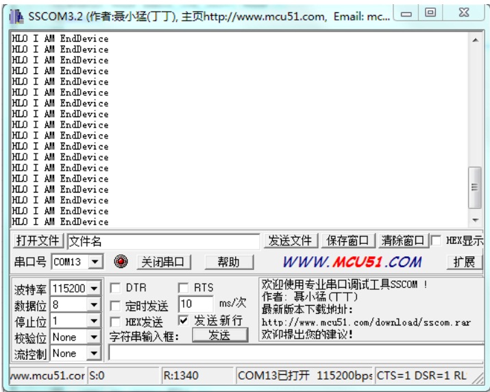
图5-36协调器端数据接收测试图
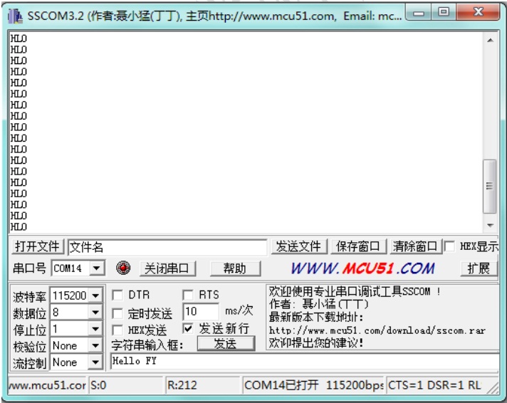
图5-37终端节点端串口数据接收测试图
从测试效果可以看出,终端节点和协调器每隔1s会收到一次握手数据,终端节点成功加入网络后每隔1s向协调器发送一串“HLO I AM EndDevice”,当协调器收到终端节点的握手数据会向终端节点发送回应字符“HLO”,测试效果与预期相符。
 STM32
STM32 MCU
MCU 通讯及无线技术
 物联网技术
物联网技术 电子DIY
电子DIY 板卡试用
板卡试用 基础知识
基础知识 软件与操作系统
 我爱生活
我爱生活 小e食堂
小e食堂