
毫米波用户需要通过测试连续波来确认TI毫米波芯片****射频信号的频率的准确性。用户对联参考设计板上进行****天线的连续波测试有不同的测试要求。下面介绍三种不同测试场景的测试流程。
测试条件:
硬件平台: MMWCAS-RF-EVM (revE)/MMWCAS-DSP-EVM
PC软件: mmwave studio 3.00.00.14
AWR2243 ES1.1的固件补丁: mmwave_dfp_02_02_03_01
频谱分析仪
测试场景一
1. 测试要求:对级联板上每个AWR2243所有3根****天线同时****连续波的测试。
2. 测试流程:
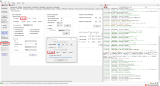
先在mmwave studio里运行下面的脚本进行所有4片AWR2243的参数配置。\mmwave_studio_03_00_00_14\mmWaveStudio\Scripts\Cascade\Cascade_ConfiguraTIon_ContStream.lua (测试脚本已经包含在mmwave studio里)
然后运行下面的脚本。这个脚本会先使能芯片Slave 3的连续波****,然后使能Slave2, Slave1,Master芯片。接着停止所有芯片的信号****。最后保存相关ADC数据到SSD硬盘上,传送给PC。\mmwave_studio_03_00_00_14\mmWaveStudio\Scripts\Cascade\Cascade_Capture_ContStream.lua(测试脚本已经包含在mmwave studio里)
通过频谱仪抓取和观测芯片的****信号。
测试场景二
1. 测试要求:对级联板的AWR2243 主芯片(master)的单****天线进行连续波的测试。
2. 测试流程:
以主芯片的TX0天线为例 (RadarDevice1)
a. 配置主芯片。
在mmwave studio里运行下面的脚本:
Cascade_ConfiguraTIon_ContStream_master_example.lua (具体内容见附录)
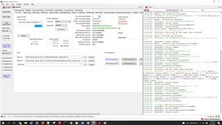
运行脚本后的mmwave studio界面信息如下:
b. ****连续波。
运行下面的脚本:\mmwave_studio_03_00_00_14\mmWaveStudio\Scripts\Cascade\Cascade_Capture_ContStream.lua(测试脚本已经包含在mmwave studio里)
c. 通过频谱仪抓取和观测芯片的****信号。
测试场景三
1. 测试要求:对级联板的AWR2243 从芯片(slave)的单****天线进行连续波的测试。
2. 测试流程:
以slave2芯片的TX1天线为例 (RadarDevice3)
a. 配置从芯片。
在mmwave studio里运行下面的脚本:Cascade_ConfiguraTIon_ContStream_slave_example.lua(具体内容见附录)
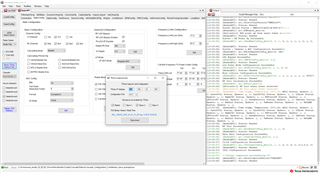
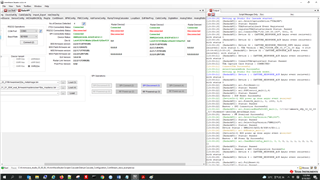
运行脚本后的mmwave studio界面信息如下:
b. ****连续波。
运行下面的脚本:\mmwave_studio_03_00_00_14\mmWaveStudio\Scripts\Cascade\Cascade_Capture_ContStream.lua(测试脚本已经包含在mmwave studio里)
c. 通过频谱仪抓取和观测芯片的****信号。
注意事项:
如果改变了AWR2243的ChanNAdcConfig_mult 参数(相对于上一次配置),用户必须对板子进行断电,再上电的操作。
常见问题:
1. 问题:如何使能、不使能主芯片或者是从芯片里的不同****天线TX?
答案::用户需要修改配置参数的LUA脚本里ar1.ChanNAdcConfig_mult 函数的Tx0En/Tx1En/Tx2En 参数。关于这个函数的更多信息见下。对于Tx0En/Tx1En/Tx2En, 1表示使能,0表示不使能。
Int32 ar1.ChanNAdcConfig_mult(UInt16 RadarDeviceId, UInt16 Tx0En, UInt16 Tx1En, UInt16 Tx2En, UInt16 Rx0En, UInt16 Rx1En, UInt16 Rx2En, UInt32 Rx3En, Int32 BitsVal, UInt32 FmtVal, UInt32 IQSwap, UInt16 CasCadeMode) - Static device config API which defines configure both the Transmiter and Reciever channels of Radar device and also ADC data format output
_I_ UInt16 RadarDeviceId - Radar Device Id
_I_ UInt16 Tx0En - Tx0 channel
_I_ UInt16 Tx1En - Tx1 channel
_I_ UInt16 Tx2En - Tx2 channel
_I_ UInt16 Rx0En - Rx0 channel
_I_ UInt16 Rx1En - Rx1 channnel
_I_ UInt16 Rx2En - Rx2 channel
_I_ UInt32 Rx3En - Rx3 channel[b15:0] + (CascadePinOutCfg[b31:16] b16:ClkOutMasterDis, b17:SynOutMasterDis, b18:ClkOutSlaveEna, b19:SynOutSlaveEna, b20:IntLOMasterEna, b21:OSCClkOutMasterDis, b22:INTFRCMasterEna)
_I_ Int32 BitsVal - Number of ADC bits
_I_ UInt32 FmtVal - ADC output format[b15:0] + FullScaleReductionFactor[b31:16]
_I_ UInt32 IQSwap - ADC Mode
_I_ UInt16 CasCadeMode - CascadeMode(Single Chip: 0x0000, MultiChip Master:0x0001, MultiChip Slave:0x0002)
2. 问题:如何使能或者关闭级联板上不同的从芯片?
答案:用户需要修改配置参数的LUA里RadarDevice的设置。RadarDevice里dev1是主芯片,dev2、dev3、dev4是从芯片。
例如: RadarDevice = {1, 0, 1, 0} -- {dev1, dev2, dev3, dev4}, 1: Enable, 0: Disable
3. 问题:如何改变连续波的频率?
答案:用户需要修改配置参数的LUA里ar1.ContStrConfig_mult函数的startFreqConst参数值。
Int32 ar1.ContStrConfig_mult(UInt16 RadarDeviceId, Double startFreqConst, UInt16 digOutSampleRate, Char rxGain, Char hpfCornerFreq1, Char hpfCornerFreq2, UInt32 tx0OutPowerBackoffCode, UInt32 tx1OutPowerBackoffCode, UInt32 tx2OutPowerBackoffCode, UInt16 tx0PhaseShifter, UInt16 tx1PhaseShifter, UInt32 tx2PhaseShifter) - Continuous Streming Configuration API defines Configuration of the data path to transfer the captured ADC samples continuously without missing any sample to external Device(host)
_I_ UInt16 RadarDeviceId - Radar Device Id
_I_ Double startFreqConst - Start Frequency for each profile of chirp in GHz
_I_ UInt16 digOutSampleRate - ADC sampling rate for each profile in ksps
_I_ Char rxGain - Rx gain for each profile in dB
_I_ Char hpfCornerFreq1 - HPF1 corner frequency for each profile in KHz
_I_ Char hpfCornerFreq2 - HPF2 corner frequency for each profile in KHz
_I_ UInt32 tx0OutPowerBackoffCode - How much the trasmit power should be reduced from Max in Tx0 Channel
_I_ UInt32 tx1OutPowerBackoffCode - How much the trasmit power should be reduced from Max in Tx1 Channel
_I_ UInt32 tx2OutPowerBackoffCode - How much the trasmit power should be reduced from Max in Tx2 Channel
_I_ UInt16 tx0PhaseShifter - The additional phase shift to be introduced on Tx0 Channel
_I_ UInt16 tx1PhaseShifter - The additional phase shift to be introduced on Tx1 Channel
_I_ UInt32 tx2PhaseShifter - The additional phase shift to be introduced on Tx2 Channel(b0:15) + ForceSelect(b16) + VCOSelecct(b17))
附录:
1.	Cascade_Configuration_ContStream_master_example.lua
----------------------------------------User Constants--------------------------------------------

dev_list           =    {1, 2, 4, 8}       -- Device map
RadarDevice        =    {1, 0, 0, 0}       -- {dev1, dev2, dev3, dev4}, 1: Enable, 0: Disable
cascade_mode_list  =    {0, 2, 2, 2}       -- 0: Single chip, 1: Master, 2: Slave //Chris: need to set in code directly

-- F/W Download Path

-- Uncomment the next line if you wish to pop-up a dialog box to select the firmware image file
-- Otherwise, hardcode the path to the firmware metaimage below
-- By default, the firmware filename is: xwr22xx_metaImage.bin

-- metaImagePath   =   RSTD.BrowseForFile(RSTD.GetSettingsPath(), "bin", "Browse to .bin file")
-- For 2243 ES1.1 devices
metaImagePath            =   "C:\\ti\\mmwave_dfp_02_02_03_01\\firmware\\xwr22xx_metaImage.bin"
-- For 2243 ES1.0 devices
-- metaImagePath            =   "C:\\ti\\mmwave_dfp_02_02_00_02\\firmware\\xwr22xx_metaImage.bin"

-- IP Address for the TDA2 Host Board
-- Change this accordingly for your setup

TDA_IPAddress           =   "192.168.33.180"

-- Device map of all the devices to be enabled by TDA
-- 1 - master ; 2- slave1 ; 4 - slave2 ; 8 - slave3

deviceMapOverall  =   RadarDevice[1] + (RadarDevice[2]*2) + (RadarDevice[3]*4) + (RadarDevice[4]*8)
deviceMapSlaves   =   (RadarDevice[2]*2) + (RadarDevice[3]*4) + (RadarDevice[4]*8)

------------------------------ API Configuration ------------------------------------------------

-- 1. Connection to TDA. 2. Selecting Cascade/Single Chip.  3. Selecting 2-chip/4-chip

WriteToLog("Setting up Studio for Cascade started..\n", "blue")

if(0 == ar1.ConnectTDA(TDA_IPAddress, 5001, deviceMapOverall)) then
    WriteToLog("ConnectTDA Successful\n", "green")
else
    WriteToLog("ConnectTDA Failed\n", "red")
    return -1
end

if(0 == ar1.selectCascadeMode(1)) then
    WriteToLog("selectCascadeMode Successful\n", "green")
else
    WriteToLog("selectCascadeMode Failed\n", "red")
    return -1
end

WriteToLog("Setting up Studio for Cascade ended..\n", "blue")

--Master Initialization

-- SOP Mode Configuration
if (0 == ar1.SOPControl_mult(1, 4)) then
    WriteToLog("Master : SOP Reset Successful\n", "green")
else
    WriteToLog("Master : SOP Reset Failed\n", "red")
    return -1
end

-- SPI Connect
if (0 == ar1.PowerOn_mult(1, 0, 1000, 0, 0)) then
    WriteToLog("Master : SPI Connection Successful\n", "green")
else
    WriteToLog("Master : SPI Connection Failed\n", "red")
    return -1
end

-- Firmware Download. (SOP 4 - MetaImage)
if (0 == ar1.DownloadBssFwOvSPI_mult(1, metaImagePath)) then
    WriteToLog("Master : FW Download Successful\n", "green")
else
    WriteToLog("Master : FW Download Failed\n", "red")
    return -1
end

-- RF Power Up
if (0 == ar1.RfEnable_mult(1)) then
    WriteToLog("Master : RF Power Up Successful\n", "green")
else
    WriteToLog("Master : RF Power Up Failed\n", "red")
    return -1
end

-- Channel & ADC Configuration
if (0 == ar1.ChanNAdcConfig_mult(1,1,0,0,1,1,1,1,2,1,0,0)) then
    WriteToLog("Master : Channel & ADC Configuration Successful\n", "green")
else
    WriteToLog("Master : Channel & ADC Configuration Failed\n", "red")
    return -2
end


-- All devices together

-- Including this depends on the type of board being used.
-- LDO configuration
if (0 == ar1.RfLdoBypassConfig_mult(deviceMapOverall, 3)) then
    WriteToLog("LDO Bypass Successful\n", "green")
else
    WriteToLog("LDO Bypass failed\n", "red")
    return -2
end

-- Low Power Mode Configuration
if (0 == ar1.LPModConfig_mult(deviceMapOverall,0, 0)) then
    WriteToLog("Low Power Mode Configuration Successful\n", "green")
else
    WriteToLog("Low Power Mode Configuration failed\n", "red")
    return -2
end

-- Miscellaneous Control Configuration
if (0 == ar1.SetMiscConfig_mult(deviceMapOverall, 1, 0, 0, 0)) then
    WriteToLog("Misc Control Configuration Successful\n", "green")
else
    WriteToLog("Misc Control Configuration failed\n", "red")
    return -2
end

-- Edit this API to enable/disable the boot time calibration. Enabled by default.
-- RF Init Calibration Configuration
if (0 == ar1.RfInitCalibConfig_mult(deviceMapOverall, 1, 1, 1, 1, 1, 1, 1, 65537)) then
    WriteToLog("RF Init Calibration Successful\n", "green")
else
    WriteToLog("RF Init Calibration failed\n", "red")
    return -2
end

-- RF Init
if (0 == ar1.RfInit_mult(deviceMapOverall)) then
    WriteToLog("RF Init Successful\n", "green")
else
    WriteToLog("RF Init failed\n", "red")
    return -2
end

---------------------------Data Configuration----------------------------------

-- Data path Configuration
if (0 == ar1.DataPathConfig_mult(deviceMapOverall, 0, 1, 0)) then
    WriteToLog("Data Path Configuration Successful\n", "green")
else
    WriteToLog("Data Path Configuration failed\n", "red")
    return -3
end

-- Clock Configuration
if (0 == ar1.LvdsClkConfig_mult(deviceMapOverall, 1, 1)) then
    WriteToLog("Clock Configuration Successful\n", "green")
else
    WriteToLog("Clock Configuration failed\n", "red")
    return -3
end

-- CSI2 Configuration
if (0 == ar1.CSI2LaneConfig_mult(deviceMapOverall, 1, 0, 2, 0, 4, 0, 5, 0, 3, 0, 0)) then
    WriteToLog("CSI2 Configuration Successful\n", "green")
else
    WriteToLog("CSI2 Configuration failed\n", "red")
    return -3
end

2.	Cascade_Configuration_ContStream_slave_example.lua
----------------------------------------User Constants--------------------------------------------

dev_list           =    {1, 2, 4, 8}       -- Device map
RadarDevice        =    {1, 0, 1, 0}       -- {dev1, dev2, dev3, dev4}, 1: Enable, 0: Disable
cascade_mode_list  =    {1, 2, 2, 2}       -- 0: Single chip, 1: Master, 2: Slave

-- F/W Download Path

-- Uncomment the next line if you wish to pop-up a dialog box to select the firmware image file
-- Otherwise, hardcode the path to the firmware metaimage below
-- By default, the firmware filename is: xwr22xx_metaImage.bin

-- metaImagePath   =   RSTD.BrowseForFile(RSTD.GetSettingsPath(), "bin", "Browse to .bin file")
-- For 2243 ES1.1 devices
metaImagePath            =   "C:\\ti\\mmwave_dfp_02_02_03_01\\firmware\\xwr22xx_metaImage.bin"
-- For 2243 ES1.0 devices
-- metaImagePath            =   "C:\\ti\\mmwave_dfp_02_02_00_02\\firmware\\xwr22xx_metaImage.bin"

-- IP Address for the TDA2 Host Board
-- Change this accordingly for your setup

TDA_IPAddress           =   "192.168.33.180"

-- Device map of all the devices to be enabled by TDA
-- 1 - master ; 2- slave1 ; 4 - slave2 ; 8 - slave3

deviceMapOverall  =   RadarDevice[1] + (RadarDevice[2]*2) + (RadarDevice[3]*4) + (RadarDevice[4]*8)
deviceMapSlaves   =   (RadarDevice[2]*2) + (RadarDevice[3]*4) + (RadarDevice[4]*8)

------------------------------ API Configuration ------------------------------------------------

-- 1. Connection to TDA. 2. Selecting Cascade/Single Chip.  3. Selecting 2-chip/4-chip

WriteToLog("Setting up Studio for Cascade started..\n", "blue")

if(0 == ar1.ConnectTDA(TDA_IPAddress, 5001, deviceMapOverall)) then
    WriteToLog("ConnectTDA Successful\n", "green")
else
    WriteToLog("ConnectTDA Failed\n", "red")
    return -1
end

if(0 == ar1.selectCascadeMode(1)) then
    WriteToLog("selectCascadeMode Successful\n", "green")
else
    WriteToLog("selectCascadeMode Failed\n", "red")
    return -1
end

WriteToLog("Setting up Studio for Cascade ended..\n", "blue")

--Master Initialization

-- SOP Mode Configuration
if (0 == ar1.SOPControl_mult(1, 4)) then
    WriteToLog("Master : SOP Reset Successful\n", "green")
else
    WriteToLog("Master : SOP Reset Failed\n", "red")
    return -1
end

-- SPI Connect
if (0 == ar1.PowerOn_mult(1, 0, 1000, 0, 0)) then
    WriteToLog("Master : SPI Connection Successful\n", "green")
else
    WriteToLog("Master : SPI Connection Failed\n", "red")
    return -1
end

-- Firmware Download. (SOP 4 - MetaImage)
if (0 == ar1.DownloadBssFwOvSPI_mult(1, metaImagePath)) then
    WriteToLog("Master : FW Download Successful\n", "green")
else
    WriteToLog("Master : FW Download Failed\n", "red")
    return -1
end

-- RF Power Up
if (0 == ar1.RfEnable_mult(1)) then
    WriteToLog("Master : RF Power Up Successful\n", "green")
else
    WriteToLog("Master : RF Power Up Failed\n", "red")
    return -1
end

-- Channel & ADC Configuration
if (0 == ar1.ChanNAdcConfig_mult(1,0,0,0,1,1,1,1,2,1,0,1)) then
    WriteToLog("Master : Channel & ADC Configuration Successful\n", "green")
else
    WriteToLog("Master : Channel & ADC Configuration Failed\n", "red")
    return -2
end

-- Slaves Initialization

for i=2,table.getn(RadarDevice) do
    local status    =    0
    if ((RadarDevice[1]==1) and (RadarDevice[i]==1)) then

        -- SOP Mode Configuration
        if (0 == ar1.SOPControl_mult(dev_list[i], 4)) then
            WriteToLog("Device "..i.." : SOP Reset Successful\n", "green")
        else
            WriteToLog("Device "..i.." : SOP Reset Failed\n", "red")
            return -1
        end

        -- SPI Connect
        if (0 == ar1.AddDevice(dev_list[i])) then
            WriteToLog("Device "..i.." : SPI Connection Successful\n", "green")
        else
            WriteToLog("Device "..i.." : SPI Connection Failed\n", "red")
            return -1
        end

    end
end

-- Firmware Download. (SOP 4 - MetaImage)
if (0 == ar1.DownloadBssFwOvSPI_mult(deviceMapSlaves, metaImagePath)) then
    WriteToLog("Slaves : FW Download Successful\n", "green")
else
    WriteToLog("Slaves : FW Download Failed\n", "red")
    return -1
end

-- RF Power Up
if (0 == ar1.RfEnable_mult(deviceMapSlaves)) then
    WriteToLog("Slaves : RF Power Up Successful\n", "green")
else
    WriteToLog("Slaves : RF Power Up Failed\n", "red")
    return -1
end

-- Channel & ADC Configuration
if (0 == ar1.ChanNAdcConfig_mult(deviceMapSlaves,0,1,0,1,1,1,1,2,1,0,2)) then
    WriteToLog("Slaves : Channel & ADC Configuration Successful\n", "green")
else
    WriteToLog("Slaves : Channel & ADC Configuration Failed\n", "red")
    return -2
end

-- All devices together

-- Including this depends on the type of board being used.
-- LDO configuration
if (0 == ar1.RfLdoBypassConfig_mult(deviceMapOverall, 3)) then
    WriteToLog("LDO Bypass Successful\n", "green")
else
    WriteToLog("LDO Bypass failed\n", "red")
    return -2
end

-- Low Power Mode Configuration
if (0 == ar1.LPModConfig_mult(deviceMapOverall,0, 0)) then
    WriteToLog("Low Power Mode Configuration Successful\n", "green")
else
    WriteToLog("Low Power Mode Configuration failed\n", "red")
    return -2
end

-- Miscellaneous Control Configuration
if (0 == ar1.SetMiscConfig_mult(deviceMapOverall, 1, 0, 0, 0)) then
    WriteToLog("Misc Control Configuration Successful\n", "green")
else
    WriteToLog("Misc Control Configuration failed\n", "red")
    return -2
end

-- Edit this API to enable/disable the boot time calibration. Enabled by default.
-- RF Init Calibration Configuration
if (0 == ar1.RfInitCalibConfig_mult(deviceMapOverall, 1, 1, 1, 1, 1, 1, 1, 65537)) then
    WriteToLog("RF Init Calibration Successful\n", "green")
else
    WriteToLog("RF Init Calibration failed\n", "red")
    return -2
end

-- RF Init
if (0 == ar1.RfInit_mult(deviceMapOverall)) then
    WriteToLog("RF Init Successful\n", "green")
else
    WriteToLog("RF Init failed\n", "red")
    return -2
end

---------------------------Data Configuration----------------------------------

-- Data path Configuration
if (0 == ar1.DataPathConfig_mult(deviceMapOverall, 0, 1, 0)) then
    WriteToLog("Data Path Configuration Successful\n", "green")
else
    WriteToLog("Data Path Configuration failed\n", "red")
    return -3
end

-- Clock Configuration
if (0 == ar1.LvdsClkConfig_mult(deviceMapOverall, 1, 1)) then
    WriteToLog("Clock Configuration Successful\n", "green")
else
    WriteToLog("Clock Configuration failed\n", "red")
    return -3
end

-- CSI2 Configuration
if (0 == ar1.CSI2LaneConfig_mult(deviceMapOverall, 1, 0, 2, 0, 4, 0, 5, 0, 3, 0, 0)) then
    WriteToLog("CSI2 Configuration Successful\n", "green")
else
    WriteToLog("CSI2 Configuration failed\n", "red")
    return -3
end
 我要赚赏金
我要赚赏金 STM32
STM32 MCU
MCU 通讯及无线技术
 物联网技术
物联网技术 电子DIY
电子DIY 板卡试用
板卡试用 基础知识
基础知识 软件与操作系统
 我爱生活
我爱生活 小e食堂
小e食堂

