

十七、PWM模块实现H桥直流电机驱动
本次试验又是一个新模块的实验,本实验的大致工作流程使这样的:
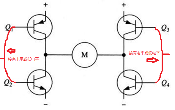
1、有五个按钮,以中断的方式分别控制电机的五个基本状态:正转(+ run)、反转(- run)、停止(stop)、加速(+ speed)和减速(- speed)。通过这五个基本状态的组合还有正转加速、反转加速等,通过H桥电路对直流电机的运行状态进行全方位的控制。说到H桥电路,下面我先说一下H桥电路的基本电路图及其工作原理:
下图所示为一个典型的直流电机控制电路:
下图所示为电机朝一个方向旋转的示意图:

下图所示是电机朝另一个方向旋转的示意图:

下图为典型的实用的H桥电路图:

本次实验用到的H桥电路图如下图所示:

以上为科普知识。。。未完待续。。。。
大家可以先看看视频,一睹为快,链接地址如下:
http://v.youku.com/v_show/id_XNDQ4MTk0ODMy.html
十七、PWM模块实现H桥直流电机驱动
本次实验用到的模块:
1:RL78/G13核心开发板:产生2路PWM波驱动H桥直流电机驱动电路
2:LCD1602液晶显示器:显示直流电机的运行状态和占空比
3:H桥直流电机驱动电路:实现对电机的正反转控制
4:直流电机:型号为:N13LB110
本次实验的CubeSuite+编程及设置:
本次实验的Timer模块使用到的通道情况如下:
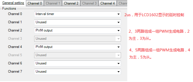
本次实验的PWM主从通道设置方式,(每一路PWM波就需要2路通道,本次实验采用2和3一组,4和5一组),通道的搭配选择是有讲究的,具体是这样的:
通道0、2、4、6可以作为主通道使用,通道1至7可以作为从通道使用,但是还要有一个条件:
从通道的通道号一定要大于主通道的通道号,例如:若选2通道为主通道,则只有3、4、5、6、7可以与通道2配合作为其从通道,而通道1却不可以,还有一个规则:
从通道与主通道之间不可有另外一个主通道,例如:若选2、4分别为2个PWM生成器的主通道,则通道5、6、7不可作为通道2的从通道,因为中间有一个通道4为另外一个主通道。
详细内容请参考RL78/G13的datasheet的第359页:时钟单元的基本规则,这里对其有详细的描述,下面上个图参考一下先:

下面上图:第一个PWM模块的主通道Channel2设置:

第一个PWM模块的从通道Channel3设置:

第二个PWM模块的主通道4的设置与通道2的设置完全相同,从通道5的设置与通道3的设置完全相同。
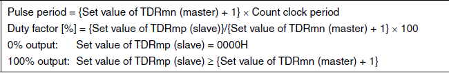
PWM的周期和占空比计算方式如下图所示:
5个中断按键的中断函数如下程序所示:
__interrupt static void r_key_interrupt(void)
{
/* Start user code. Do not edit comment generated here */
switch (P6)
{
case 254: key0input =1; //the key name is "- run".
duty2Period = 0; //the output of PWM2 is duty=0% (PWM2==0) PWM wave.
cycle2Period = 3199;
duty4Period = 1600; //the output of PWM4 is duty=50% PWM wave.
cycle4Period =3199;
//LCD_dispkey0();
break;
case 253: key1input =1; //the key name is "stop"
duty2Period = 3200;
cycle2Period = 3199; // the output of both TO03 and TO05 is "1", so the motor is "stop".
duty4Period = 3200;
cycle4Period = 3199;
break;
case 251: key2input =1; //the key name is "+ run".
duty2Period = 1600; //the output of PWM2 is duty=50% PWM wave.
cycle2Period = 3199;
duty4Period = 0; //the output of PWM4 is duty=0% (PWM4==0) PWM wave.
cycle4Period = 3199;
break;
case 247: key3input =1; //the key name is "- speed".
if (duty2Period == 0)
{
if (duty4Period > 50) //when the PWM4 is the engine, decrease the duty of PWM4.
{
duty4Period = duty4Period - 50;
}
else
{
duty4Period = 0; //the speed minium is "0" always ("stop").
}
}
else if ( duty4Period == 0)
{
if (duty2Period > 50) //when the PWM2 is the engine, decrease the duty of PWM2.
{
duty2Period = duty2Period - 50;
}
else
{
duty2Period = 0; //the speed minium is "0" always ("stop").
}
}
else
{
duty2Period = cycle2Period + 1; //put the output of both PWM2 and PWM4 high level "1".
duty4Period = cycle4Period + 1; //then the motor will "stop".
}
break;
case 239: key4input =1; //the key name is "+ speed".
if (duty2Period == 0)
{
if (duty4Period < cycle4Period -49) //when the PWM4 is the engine, increase the duty of PWM4.
{
duty4Period = duty4Period + 50;
}
else
{
duty4Period = cycle4Period + 1; //the speed maxium is "1" always.
}
}
else if ( duty4Period == 0)
{
if (duty2Period < cycle2Period -49) //when the PWM2 is the engine, increase the duty of PWM2.
{
duty2Period = duty2Period + 50;
}
else
{
duty2Period = cycle2Period + 1; //the speed maxium is "1" always.
}
}
else
{
duty2Period = cycle2Period + 1; //put the output of both PWM2 and PWM4 high level "1".
duty4Period = cycle4Period + 1; //then the motor will "stop".
}
break;
default:
{
//duty2Period = cycle2Period + 1; //put the output of both PWM2 and PWM4 high level "1".
//duty4Period = cycle4Period + 1; //then the motor will "stop".
}
}
KRIF=0; //clear the flag of the keyinterrupt
/* End user code. Do not edit comment generated here */
}
Timer的占空比更新程序,由于Timer中TDR的更新只能在主通道中断产生之后,而且要求中断产生后要立即更新,所以就将TDR02和TDR03的数据更新放在了通道2的中断函数内,如下程序:
__interrupt static void r_tau0_channel2_interrupt(void)
{
/* Start user code. Do not edit comment generated here */
TDR02=cycle2Period;
TDR03=duty2Period;
/* End user code. Do not edit comment generated here */
}
另一个PWM的中断函数与之类似,如下所示:
__interrupt static void r_tau0_channel4_interrupt(void)
{
/* Start user code. Do not edit comment generated here */
TDR04=cycle4Period;
TDR05=duty4Period;
/* End user code. Do not edit comment generated here */
}
最后,说一下本次试验PWM波输出的两个管脚分别为:P31:TO03、P05:TO05
接下来上几张效果图:
系统搭建组装图:

直流电机旋转中图:

LCD1602显示电机运行状态图:

LCD1602显示数据的格式如下:
第一路PWM的占空比(%) 正转(+)/反转(-) 常显字符“run”
第二路PWM的占空比(%) 加速(+)/减速(-) 常显字符“speed”
好了,最后上个视频链接:
http://v.youku.com/v_show/id_XNDQ4MTk0ODMy.html
好的,期待着EEPW友们提出改进意见,更期待着你们的作品。。。一起分享。。。共同学习。。。
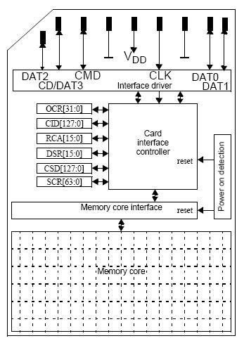
准备做一个基于RL78/G13的SD卡读写器,方案的初步构想是通过本次开发板的虚拟串口来完成对外接SD卡的读和写,不知本设想是否具有可行性,因为通过虚拟串口对SD卡进行读写是不是会很慢,在这里先附上一份关于SD卡读写的SPI通信协议,以抛砖引玉
SD卡内部结构图:
详见如下文档:
http://share.eepw.com.cn/share/download/id/78854
SD卡内部结构及引脚
SD卡管脚图
SPI模式下SD各管脚名称
SD卡主要引脚和功能
MicroSD卡管脚图
MicroSD卡管脚名称
SPI命令格式
详见如下文档:
http://share.eepw.com.cn/share/download/id/78854
SD卡内部结构及引脚
SD卡管脚图
SPI模式下SD各管脚名称
SD卡主要引脚和功能
MicroSD卡管脚图
MicroSD卡管脚名称
SPI命令格式
LCD1602液晶驱动源代码
http://share.eepw.com.cn/share/download/id/78905
PWM模块实现H桥直流马达驱动程序源代码
http://share.eepw.com.cn/share/download/id/78906
http://share.eepw.com.cn/share/download/id/78905
PWM模块实现H桥直流马达驱动程序源代码
http://share.eepw.com.cn/share/download/id/78906
回复
 我要赚赏金打赏帖 我要赚赏金打赏帖 |
|
|---|---|
| 片外存储Flash使用方法(Arduino IDE环境)被打赏¥22元 | |
| 三分钟快速上手ESP-NOW(ArduinoIDE环境)被打赏¥23元 | |
| 【S32K3XX】LPSPI参数配置说明被打赏¥21元 | |
| 在WT9932C61-TINY上实现超声波测距被打赏¥22元 | |
| 基于WT9932C61-TINY的环境构建及OLED屏驱动测试被打赏¥20元 | |
| 【S32K3XX】Core-to-Core 中断使用被打赏¥21元 | |
| 「AI编程记录--含源码」用一晚上的时间写一个esp32的示波器被打赏¥19元 | |
| STM32C0116DK开发探索记(3)被打赏¥30元 | |
| STM32C0116DK开发探索记(2)被打赏¥24元 | |
| STM32C0116DK开发探索记(1)被打赏¥29元 | |
 STM32
STM32 MCU
MCU 通讯及无线技术
 物联网技术
物联网技术 电子DIY
电子DIY 板卡试用
板卡试用 基础知识
基础知识 软件与操作系统
 我爱生活
我爱生活 小e食堂
小e食堂

