
开始整通讯了,以前没碰过SPI,找视频学习一下,列出视频地址,共大家同学习。
http://www.iqiyi.com/w_19rrd96ntp.html
看完SPI的视频,一头雾水,还是看看怎么用NFR吧,上网址:
阅读匿名的NRF驱动程序和数据发送程序,总结一下:
一、端口配置(Spi.h)
void Spi1_Init(void);
//配置SPI的用到的GPIO端口和SPI参数
u8 Spi_RW(u8 dat);
二、驱动程序部分(Nrf2401.h):
void Nrf24l01_Init(u8 model, u8 ch);
//初始化,model=1/2/3/4,ch为实用的通道号uint8_t NRF_Read_Reg(uint8_t reg);
//读寄存器
uint8_t NRF_Write_Reg(uint8_t reg, uint8_t value);
//写寄存器
uint8_t NRF_Read_Buf(uint8_t reg, uint8_t *pBuf, uint8_t uchars);
//读缓冲区
void NRF_TxPacket(uint8_t * tx_buf, uint8_t len);
//发送数据包,用于model 2/4
void NRF_TxPacket_AP(uint8_t * tx_buf, uint8_t len);
//发送数据包,用于model 3
uint8_t Nrf24l01_Check(void);
//自检
三、数据的发送接收程序(Rc.h):
void Nrf_Check_Event(void);
//判断解锁
void NRF_Send_AF(void);
//发送加速度,角速度,四元数得到的角度等
void NRF_Send_AE(void);
//接收到的RC数据
void NRF_Send_OFFSET(void);
//发送加速度偏移,角速度偏移
void NRF_Send_PID(void);
//发送RPY三个值的PID值
void NRF_Send_ARMED(void);
//发送解锁信息
分析Crazyflie的Nrf24L01的驱动程序:
该代码使用了外部中断,关于外部中断的教程,可见
http://www.cnblogs.com/alvis-jing/p/3678285.html
该博主的其他关于STM32 的文章,见
http://www.cnblogs.com/alvis-jing/category/569663.html,先mark一下。
一、驱动程序(Nrf24l01.h)
/***********************
* SPI private methods,与匿名的Spi_RW()相同 *
***********************/
static char spiSendByte(char byte)
{
/* Loop while DR register in not emplty */
while (SPI_I2S_GetFlagStatus(RADIO_SPI, SPI_I2S_FLAG_TXE) == RESET);
/* Send byte through the SPI1 peripheral */
SPI_I2S_SendData(RADIO_SPI, byte);
/* Wait to receive a byte */
while (SPI_I2S_GetFlagStatus(RADIO_SPI, SPI_I2S_FLAG_RXNE) == RESET);
/* Return the byte read from the SPI bus */
return SPI_I2S_ReceiveData(RADIO_SPI);
}
static char spiReceiveByte()
{
return spiSendByte(DUMMY_BYTE);
}
//该函数增加了SPI的中断引脚的定义
void nrfInit(void);
/* Initialisation */
void nrfInit(void)
{
SPI_InitTypeDef SPI_InitStructure;
EXTI_InitTypeDef EXTI_InitStructure;
GPIO_InitTypeDef GPIO_InitStructure;
if (isInit)
return;
/* Enable the EXTI interrupt router */
extiInit();
/* Enable SPI and GPIO clocks */
RCC_APB2PeriphClockCmd(RADIO_GPIO_SPI_CLK | RADIO_GPIO_CS_PERIF |
RADIO_GPIO_CE_PERIF | RADIO_GPIO_IRQ_PERIF, ENABLE);
/* Enable SPI and GPIO clocks */
RCC_APB1PeriphClockCmd(RADIO_SPI_CLK, ENABLE);
/* Configure main clock */
GPIO_InitStructure.GPIO_Pin = RADIO_GPIO_CLK;
GPIO_InitStructure.GPIO_Mode = GPIO_Mode_AF_PP;
GPIO_InitStructure.GPIO_Speed = GPIO_Speed_50MHz;
GPIO_Init(RADIO_GPIO_CLK_PORT, &GPIO_InitStructure);
/* Configure SPI pins: SCK, MISO and MOSI */
GPIO_InitStructure.GPIO_Pin = RADIO_GPIO_SPI_SCK | RADIO_GPIO_SPI_MOSI;
GPIO_InitStructure.GPIO_Mode = GPIO_Mode_AF_PP;
GPIO_InitStructure.GPIO_Speed = GPIO_Speed_50MHz;
GPIO_Init(RADIO_GPIO_SPI_PORT, &GPIO_InitStructure);
//* Configure MISO */
GPIO_InitStructure.GPIO_Pin = RADIO_GPIO_SPI_MISO;
GPIO_InitStructure.GPIO_Mode = GPIO_Mode_IN_FLOATING;
GPIO_Init(RADIO_GPIO_SPI_PORT, &GPIO_InitStructure);
/* Configure I/O for the Chip select */
GPIO_InitStructure.GPIO_Pin = RADIO_GPIO_CS;
GPIO_InitStructure.GPIO_Mode = GPIO_Mode_Out_PP;
GPIO_Init(RADIO_GPIO_CS_PORT, &GPIO_InitStructure);
/* Configure the interruption (EXTI Source) */
GPIO_InitStructure.GPIO_Pin = RADIO_GPIO_IRQ;
GPIO_InitStructure.GPIO_Speed = GPIO_Speed_50MHz;
GPIO_InitStructure.GPIO_Mode = GPIO_Mode_IN_FLOATING;
GPIO_Init(RADIO_GPIO_IRQ_PORT, &GPIO_InitStructure);
GPIO_EXTILineConfig(RADIO_GPIO_IRQ_SRC_PORT, RADIO_GPIO_IRQ_SRC);
EXTI_InitStructure.EXTI_Line = RADIO_GPIO_IRQ_LINE;
EXTI_InitStructure.EXTI_Mode = EXTI_Mode_Interrupt;
EXTI_InitStructure.EXTI_Trigger = EXTI_Trigger_Falling;
EXTI_InitStructure.EXTI_LineCmd = ENABLE;
EXTI_Init(&EXTI_InitStructure);
// Clock the radio with 16MHz
RCC_MCOConfig(RCC_MCO_HSE);
/* disable the chip select */
RADIO_DIS_CS();
/* Configure I/O for the Chip Enable */
GPIO_InitStructure.GPIO_Pin = RADIO_GPIO_CE;
GPIO_InitStructure.GPIO_Mode = GPIO_Mode_Out_PP;
GPIO_Init(RADIO_GPIO_CE_PORT, &GPIO_InitStructure);
/* disable the chip enable */
RADIO_DIS_CE();
/* SPI configuration */
SPI_InitStructure.SPI_Direction = SPI_Direction_2Lines_FullDuplex;
SPI_InitStructure.SPI_Mode = SPI_Mode_Master;
SPI_InitStructure.SPI_DataSize = SPI_DataSize_8b;
SPI_InitStructure.SPI_CPOL = SPI_CPOL_Low;
SPI_InitStructure.SPI_CPHA = SPI_CPHA_1Edge;
SPI_InitStructure.SPI_NSS = SPI_NSS_Soft;
SPI_InitStructure.SPI_BaudRatePrescaler = SPI_BaudRatePrescaler_8;
SPI_InitStructure.SPI_FirstBit = SPI_FirstBit_MSB;
SPI_InitStructure.SPI_CRCPolynomial = 7;
SPI_Init(RADIO_SPI, &SPI_InitStructure);
/* Enable the SPI */
SPI_Cmd(RADIO_SPI, ENABLE);
isInit = true;
}
//测试设备是否已经初始化
bool nrfTest(void);
// Interrupt routine
void nrfIsr(void);
/*** Defines ***/
#define RADIO_RATE_250K 0
#define RADIO_RATE_1M 1
#define RADIO_RATE_2M 2
/* Low level reg access
* FIXME: the user should not need to access raw registers...
*/
/* Read len bytes from a nRF24L register. 5 Bytes max */
unsigned char nrfReadReg(unsigned char address, char *buffer, int len);
/* Write len bytes a nRF24L register. 5 Bytes max */
unsigned char nrfWriteReg(unsigned char address, char *buffer, int len);
/* Read only one byte (useful for most of the reg.) */
unsigned char nrfRead1Reg(unsigned char address);
/* Write only one byte (useful for most of the reg.) */
unsigned char nrfWrite1Reg(unsigned char address, char byte);
//Interrupt access设置中断回调函数
//回调函数有两个,分别位于Radiolink.c和Eskylink.c
void nrfSetInterruptCallback(void (*cb)(void));
/* Low level functionality of the nrf chip */
/* Sent the NOP command. Used to get the status byte */
unsigned char nrfNop(void);
unsigned char nrfFlushRx(void);
unsigned char nrfFlushTx(void);
// Return the payload length
unsigned char nrfRxLength(unsigned int pipe);
unsigned char nrfActivate(void);
// Write the ack payload of the pipe 0
unsigned char nrfWriteAck(unsigned int pipe, char *buffer, int len);
// Read the RX payload
unsigned char nrfReadRX(char *buffer, int len);
void nrfSetChannel(unsigned int channel);
void nrfSetDatarate(int datarate);
void nrfSetAddress(unsigned int pipe, char* address);
void nrfSetEnable(bool enable);
unsigned char nrfGetStatus(void);
/* 中断服务程序,调用中断回调函数 */
void nrfIsr()
http://jaist.dl.sourceforge.net/project/freertos/FreeRTOS/V8.0.1/FreeRTOSv8.0.1.exe
你试试。
分析crazyflie四轴方案的通信模块
crazyflie的通信模块比较复杂,下面分成几贴分别讨论。
Crazyflie的通信分成几个层次,下面从通信模块的代码comm.c讨论。
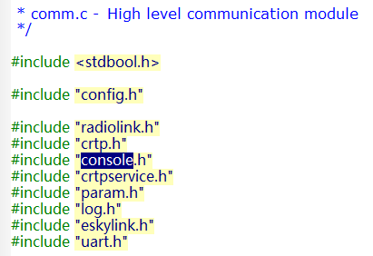
comm文件只有两个函数,一个是commInit函数,一个是commTest函数,分别负责通信的初始化和测试工作。初始化后(commInit)即实现了两个设备的通信连接,测试函数则用于测试该模块。既然commInit函数实现飞行器与遥控器的通信,我们只需要分析这个函数即可。
Code见下图
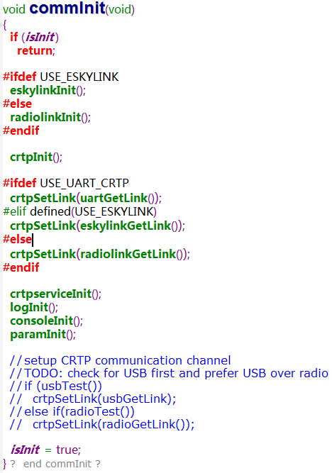
下面对每个函数分别讨论。
一、radiolinkInit()
关于esky协议,
http://sourceforge.net/p/arduinorclib/wiki/Esky%20Radio/ 两个网站有描述,不详细分析了,程序中仅仅将eskylink作为实验测试代码。
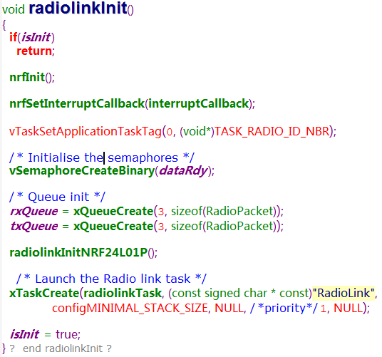
分析radiolinkInit()函数,该函数位于radiolink.c文件中。
分析函数:
1、nrfInit()
实现端口配置,中断配置,spi配置等
2、nrfSetInterruptCallback()
配置中断回调函数为radiolink的中断回调函数
3、创建信号量dataRdy和队列rxQueue、txQueue。
Queue和Task属于操作系统的概念,程序是在freeRTOS系统的环境下运行的,第5步的任务中使用。
4、初始化NRF24L01P。
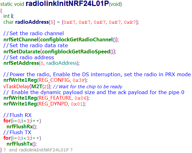
配置无线电参数,频道,数据速率,地址,模式...
5、创建radiolinkTask任务。
任务内容:
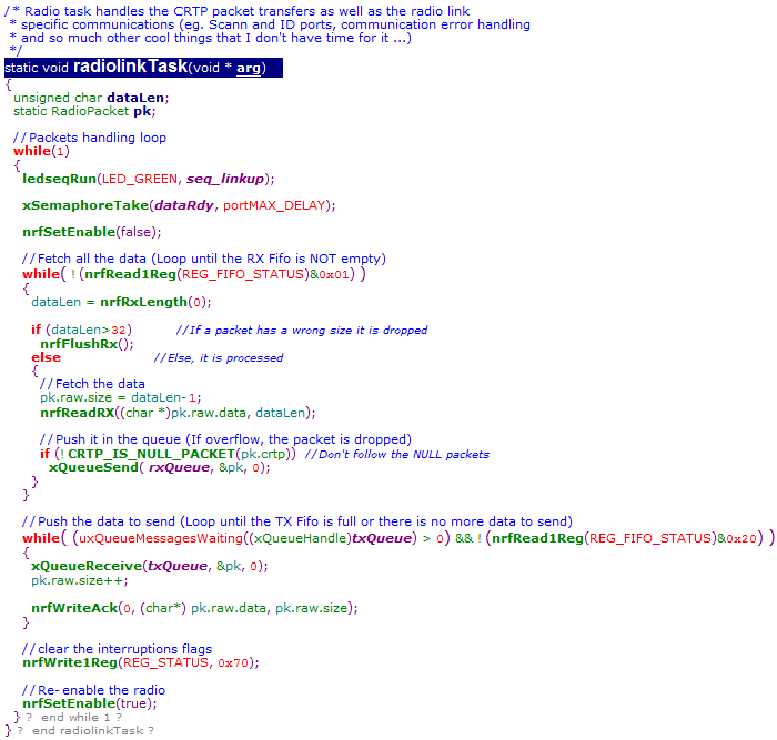
任务很清晰,不停的接收信息到rxQueue,并从txQueue取得数据包发送出去。至于从消息队列到程序员接口的操作,如下图所示:
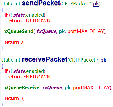
发送数据包的时候,只需要sendPacket函数将数据包pk发送到txQueue,之后radiolinkTask就会自动发送出去;接收数据包的时候,则是radiolinkTask 自动从radio中接收到的数据放入rxQueue,receivePacket函数从rxQueue中接收数据到pk中。sendPacket、receivePacket和setEnable三个函数共同组成了radio的操作,如下图:
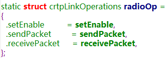
这个函数结构体通过函数

返回函数指针。
该函数位于crtp.c文件中,该文件与crtp.h文件,共同定义了crtp ( Crazy Realtime Transfer Protocol )栈
![]()

该函数创建了两个队列tmpQueue和rxQueue,并创建了两个任务crtpTxTask和crtpRxTask。来看看两个任务都做了什么。
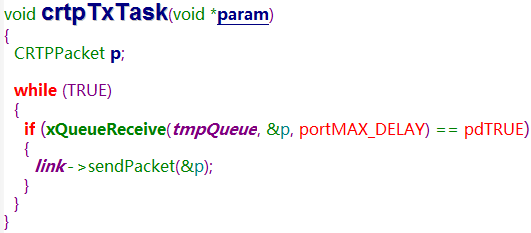
crtpTxTask任务在从tmpQueue中接收到数据包到p的地址后,调用sendPacket函数发送出去(该函数就是comm.c里面的sendPacket函数)
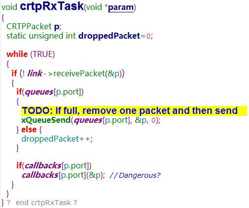
该crtpRxTask任务从链路中接收数据包到p,根据数据包的端口发送到不同端口的Queue或者丢弃,并根据不同端口调用不同的回调函数。
同comm.c一样,crtp.c提供了程序员接口函数:
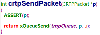
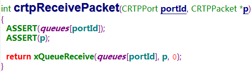
crtpSendPacket函数将数据包发送到tmpQueue中,然后通过crtpTxTask任务发送出去。crtpRxTask将接收到的数据包按端口分发到不同的queue中,crtpReceivePacket函数按端口接收队列中的数据到数据包p中。
三、crtpSetLink(radiolinkGetLink())
该函数位于crtp.c中
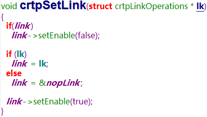
设置crtp的操作函数,该函数的参数radiolinkGetLink()在第一部分分析radiolinkInit()最后提到过,而设置的变量 link 恰恰是crtpRxTask和crtpTxTask里面的link了。
四、crtpserviceInit()
该服务控制接收端在收到数据包后是否将该数据包发送回去,感兴趣的读者自己去分析。
五、logInit()
该函数位于log.c文件中,动态log系统信息。Crtp数据包有一个日志端口CRTP_PORT_LOG,在四轴中不是必需的,这里也不分析了。
六、consoleInit()
该函数位于console.c文件中,文件中函数不多,可以全拿来分析
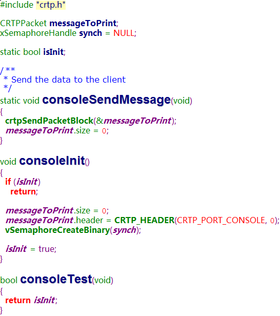
初始化函数重置了消息包的长度,设置crtp的端口为CRTP_PORT_CONSOLE,创建一个消息发送函数consoleSendMessage()。
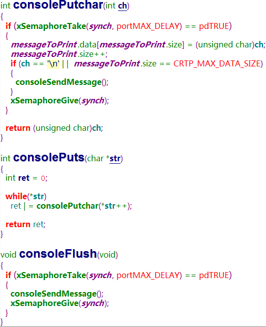
consolePutchar函数将字符加入消息数据包,在字符为’ ’或消息包达到最大长度时发送出去。
consolePuts函数...
consoleFlush函数强制发送数据包。
本程序提供了发送字符串的程序接口。
七、paramInit()
该函数位于param.c文件中,看了个大概,没全看明白,有明白的来看看。
总算凑合着看完了crazyflie四轴的通信模块,洋鬼子做出来的东西还是不错的。
 我要赚赏金打赏帖 我要赚赏金打赏帖 |
|
|---|---|
| 片外存储Flash使用方法(Arduino IDE环境)被打赏¥22元 | |
| 三分钟快速上手ESP-NOW(ArduinoIDE环境)被打赏¥23元 | |
| 【S32K3XX】LPSPI参数配置说明被打赏¥21元 | |
| 在WT9932C61-TINY上实现超声波测距被打赏¥22元 | |
| 基于WT9932C61-TINY的环境构建及OLED屏驱动测试被打赏¥20元 | |
| 【S32K3XX】Core-to-Core 中断使用被打赏¥21元 | |
| 「AI编程记录--含源码」用一晚上的时间写一个esp32的示波器被打赏¥19元 | |
| STM32C0116DK开发探索记(3)被打赏¥30元 | |
| STM32C0116DK开发探索记(2)被打赏¥24元 | |
| STM32C0116DK开发探索记(1)被打赏¥29元 | |
 STM32
STM32 MCU
MCU 通讯及无线技术
 物联网技术
物联网技术 电子DIY
电子DIY 板卡试用
板卡试用 基础知识
基础知识 软件与操作系统
 我爱生活
我爱生活 小e食堂
小e食堂

