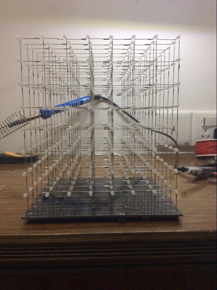
为了方便大家焊接完成后检查焊接成果。版主编写了测试程序。
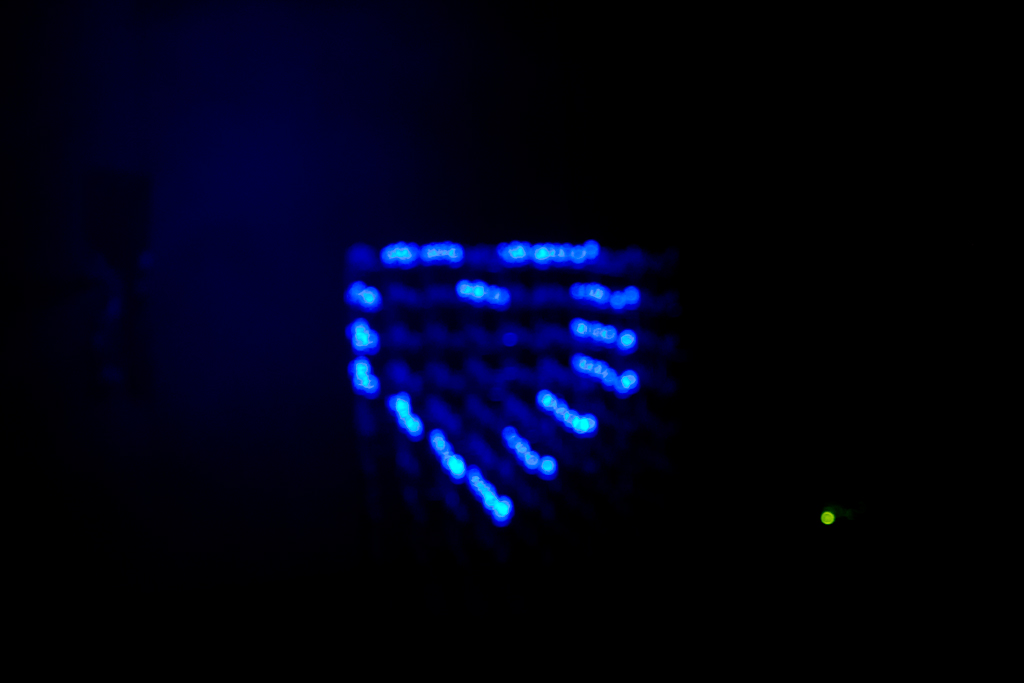
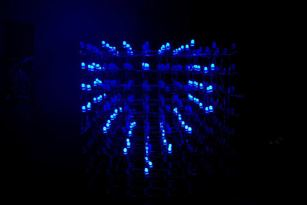
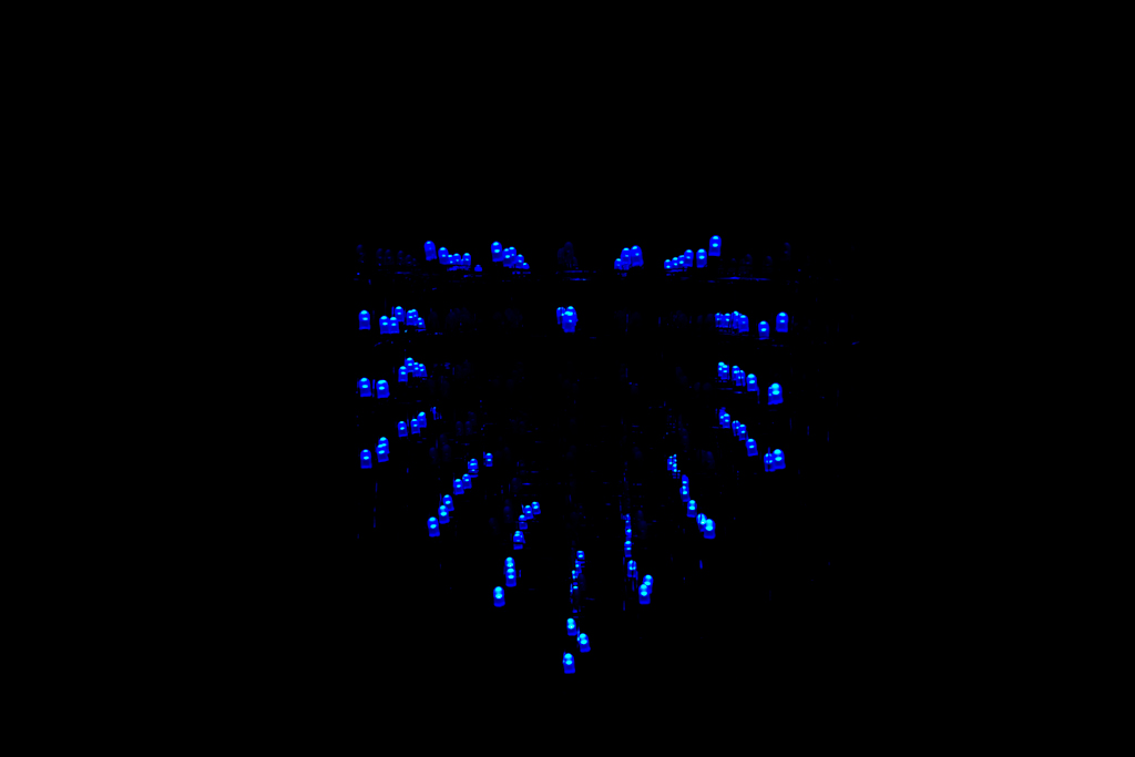
测试程序首先以列为扫描,之后以层为扫描,之后全亮,最后再全灭。循环如此。
附源代码如下:
/**
******************************************************************************
* @file main.c
* @author Jobs Zheng
* @version V1.0
* @date 2014-08-17
* @brief LEDcube 测试程序
* @note 按列扫描,按层扫描,全亮,全灭
******************************************************************************
* @attention
*
* <h2><center>© COPYRIGHT 2013 EEPW.com.cn </center></h2>
*
*
******************************************************************************
*/
/* Includes ------------------------------------------------------------------*/
#include "main.h"
#include "bsp.h"
/** @addtogroup STM32_EEPW
* @{
*/
/** @defgroup LEDCUBE
* @brief
* @{
*/
/** @defgroup LEDCUBE_Private_TypesDefinitions
* @{
*/
/**
* @}
*/
/** @defgroup LEDCUBE_Private_Defines
* @{
*/
//#define SIMULATE (1)
#define INTERVAL (500)
/**
* @}
*/
/** @defgroup LEDCUBE_Private_Macros
* @{
*/
/**
* @}
*/
/** @defgroup LEDCUBE_Private_Variables
* @{
*/
uint16_t gSecond= 0;
bool gShareMemoryBusy;
uint8_t gDisp = 0;
uint16_t gCount = 0;
uint8_t gGraphBuffer[64] = {0xFF,};
/**
* @}
*/
/** @defgroup LEDCUBE_Private_FunctionPrototypes
* @{
*/
void AutoReFresh(uint8_t *BufferPtr, bool gShareMemoryBusy);
/**
* @}
*/
/** @defgroup LEDCUBE_Private_Functions
* @{
*/
/**
* @brief main function
* @param
* @retval
* @date 2014-03-24
* @note
*/
void main(void)
{
gShareMemoryBusy = false;
uint8_t i;
uint8_t RollLayer[] = {0, 0x01, 0x02, 0x04, 0x08, 0x10, 0x20, 0x40, 0x80, 0xFF};
uint8_t RollRow[] = {0, 0x01, 0x02, 0x04, 0x08, 0x10, 0x20, 0x40, 0x80, 0xFF};
uint8_t RollLayerLongth = sizeof(RollLayer);
uint8_t RollRowLongth = sizeof(RollRow);
for(i = 0; i < 64; i++)
{
gShareMemoryBusy = true;
gGraphBuffer[i] = 0xFF;
gShareMemoryBusy = false;
}
i = 0;
#ifndef SIMULATE
Bsp_Init(); /*!< 底层外设模块初始化 */
#endif
if (SysTick_Config(72000)) /*!< 1000Hz(1ms)中断间隔 */
{
while (1);
}
while(true)
{
if(gSecond == INTERVAL)
{
gSecond = 0;
if(i < RollRowLongth)
{
gShareMemoryBusy = true;
DispRow(RollRow[i], gGraphBuffer);
gShareMemoryBusy = false;
}
else
{
gShareMemoryBusy = true;
DispLayer(RollLayer[i - RollRowLongth], gGraphBuffer);
gShareMemoryBusy = false;
}
i++;
if(i == (RollRowLongth + RollLayerLongth))
{
i = 0;
}
else
{
; //nothing to do
}
}
}
}
/**
* @brief 定时刷新光立方显示
* @param uint8_t *BufferPtr: 显示图形缓存
bool MemBusy: 检查显示图形缓存是否可用,
true:正在更新缓存,此时不显示;
false:已经完成数据更新,不断刷新
* @retval
* @date 2014-08-17
* @note 1000Hz显示每一层
*/
void AutoReFresh(uint8_t *BufferPtr, bool MemBusy)
{
if(MemBusy == true)
{
// to do something
return;
}
else
{
Bsp_LayerOff(gDisp); //关闭当前层的显示
H595Disable();
gDisp++;
if(gDisp > 7)
{
gDisp = 0;
}
DispFlush(BufferPtr + gDisp * 8);
H595Enable();
Bsp_LayerOn(gDisp); //打开当前层的显示
}
}
/**
* @brief 使用systick中断产生1000Hz, 1ms中断
* @param
* @retval
* @date 2014-08-17
* @note 500Hz会出现闪烁
*/
void SysTick_Handler(void)
{
AutoReFresh((uint8_t *)gGraphBuffer, gShareMemoryBusy);
if(gSecond < INTERVAL)
{
gSecond++;
}
else
{
gSecond = INTERVAL;
}
}
/**
* @}
*/
/**
* @}
*/
/**
* @}
*/
/******************* (C) EEPW.com.cn*****END OF FILE****/
/**
******************************************************************************
* @file display.c
* @author Jobs Zheng
* @version v1.0
* @date 2014-08-17 09:59
* @brief 用来显示函数图形
* @note
******************************************************************************
* @attention
*
* <h2><center>© COPYRIGHT 2014 EEPW.com.cn </center></h2>
*
*
******************************************************************************
*/
/* Includes ------------------------------------------------------------------*/
#include "display.h"
/** @addtogroup STM32_EEPW
* @{
*/
/** @defgroup LEDCUBE
* @brief
* @{
*/
/** @defgroup LEDCUBE_Private_TypesDefinitions
* @{
*/
/**
* @}
*/
/** @defgroup LEDCUBE_Private_Defines
* @{
*/
//#define XXXX () /*!< */
/**
* @}
*/
/** @defgroup LEDCUBE_Private_Macros
* @{
*/
/**
* @}
*/
/** @defgroup LEDCUBE_Private_Variables
* @{
*/
/**
* @}
*/
/** @defgroup LEDCUBE_Private_FunctionPrototypes
* @{
*/
/**
* @}
*/
/** @defgroup LEDCUBE_Private_Functions
* @{
*/
/**
* @brief 显示某层LED灯
* @param uint8_t lay:第0位表示第0层点亮
uint8_t * bufferPtr:图形显示缓存
* @retval
* @date 2014-08-17
* @note
*/
void DispLayer(uint8_t lay, uint8_t * bufferPtr)
{
uint8_t temp[64];
uint8_t i, j;
for(i =0; i < 8; i++)
{
if(((lay >> i) & 0x01) == 0x01)
{
for(j = 0; j < 8; j++)
{
temp[i * 8 + j] = 0x00;
}
}
else
{
for(j = 0; j < 8; j++)
{
temp[i * 8 + j] = 0xFF;
}
}
}
/**
* @brief 将临时缓存区的内容拷贝至图形缓存区
*
*/
for(i = 0; i < 64; i++)
{
*(bufferPtr + i) = temp[i];
}
}
/**
* @brief 显示某列LED灯
* @param uint8_t row:第0位表示第0列点亮
uint8_t * bufferPtr:图形显示缓存
* @retval
* @date 2014-08-17
* @note
*/
void DispRow(uint8_t row, uint8_t * bufferPtr)
{
uint8_t temp[64];
uint8_t i, j;
for(i =0; i < 8; i++)
{
if(((row >> i) & 0x01) == 0x01)
{
for(j = 0; j < 8; j++)
{
temp[i + j * 8] = 0x00;
}
}
else
{
for(j = 0; j < 8; j++)
{
temp[i + j * 8] = 0xFF;
}
}
}
/**
* @brief 将临时缓存区的内容拷贝至图形缓存区
*
*/
for(i = 0; i < 64; i++)
{
*(bufferPtr + i) = temp[i];
}
}
/**
* @}
*/
/**
* @}
*/
/**
* @}
*/
/******************* (C) EEPW.com.cn*****END OF FILE****/
/**
******************************************************************************
* @file bsp.c
* @author Jobs Zheng
* @version
* @date 2014-06-15 15:54
* @brief 光立方项目工程
* @note 初始化板载硬件外设端口,spi1,spi2,uart1及时钟
******************************************************************************
* @attention
*
* <h2><center>© COPYRIGHT 2014 EEPW.com.cn </center></h2>
*
*
******************************************************************************
*/
/* Includes ------------------------------------------------------------------*/
#include "bsp.h"
#include <stdio.h>
/** @addtogroup STM32_EEPW
* @{
*/
/** @defgroup LEDCUBE
* @brief
* @{
*/
/** @defgroup LEDCUBE_Private_TypesDefinitions
* @{
*/
/**
* @}
*/
/** @defgroup LEDCUBE_Private_Defines
* @{
*/
/**
* @}
*/
/** @defgroup LEDCUBE_Private_Macros
* @{
*/
#ifdef __GNUC__
/* With GCC/RAISONANCE, small printf (option LD Linker->Libraries->Small printf
set to 'Yes') calls __io_putchar() */
#define PUTCHAR_PROTOTYPE int __io_putchar(int ch)
#else
#define PUTCHAR_PROTOTYPE int fputc(int ch, FILE *f)
#endif /* __GNUC__ */
/**
* @}
*/
/** @defgroup LEDCUBE_Private_Variables
* @{
*/
ErrorStatus HSEStartUpStatus;
/**
* @}
*/
/** @defgroup LEDCUBE_Private_FunctionPrototypes
* @{
*/
static void SysClockInit(void);
/**
* @}
*/
/** @defgroup LEDCUBE_Private_Functions
* @{
*/
/**
* @brief called from main.c
* @param
* @retval
* @date 2014-03-24
* @note
*/
void Bsp_Init(void)
{
SysClockInit();
Bsp_LayerInit();
Uart1Init(115200);
HC595_Init();
}
/**
* @brief initial the sysclock,
* @param
* @retval
* @date 2014-03-24
* @note
*/
static void SysClockInit(void)
{
/* SYSCLK, HCLK, PCLK2 and PCLK1 configuration -----------------------------*/
/* RCC system reset(for debug purpose) */
RCC_DeInit();
/* Enable HSE */
RCC_HSEConfig(RCC_HSE_ON);
/* Wait till HSE is ready */
HSEStartUpStatus = RCC_WaitForHSEStartUp();
if (HSEStartUpStatus == SUCCESS)
{
/* Enable Prefetch Buffer */
FLASH_PrefetchBufferCmd(FLASH_PrefetchBuffer_Enable);
/* Flash 2 wait state */
FLASH_SetLatency(FLASH_Latency_2);
/* HCLK = SYSCLK */
RCC_HCLKConfig(RCC_SYSCLK_Div1);
/* PCLK2 = HCLK */
RCC_PCLK2Config(RCC_HCLK_Div1);
/* PCLK1 = HCLK/2 */
RCC_PCLK1Config(RCC_HCLK_Div2);
/* PLLCLK = 12MHz * 6 = 72 MHz */
RCC_PLLConfig(RCC_PLLSource_HSE_Div1, RCC_PLLMul_6); /* 此处需要根据外部晶振的改变而改变 */
/* Enable PLL */
RCC_PLLCmd(ENABLE);
/* Wait till PLL is ready */
while (RCC_GetFlagStatus(RCC_FLAG_PLLRDY) == RESET)
{
}
/* Select PLL as system clock source */
RCC_SYSCLKConfig(RCC_SYSCLKSource_PLLCLK);
/* Wait till PLL is used as system clock source */
while(RCC_GetSYSCLKSource() != 0x08)
{
}
}
else
{ /* If HSE fails to start-up, the application will have wrong clock configuration.
User can add here some code to deal with this error */
/* Go to infinite loop */
while (1)
{
}
}
}
/**
* @brief 初始化板载8层LED灯
* @param none
* @retval none
* @date 2014-04-27
* @note
*/
void Bsp_LayerInit(void)
{
GPIO_InitTypeDef GPIO_InitStructure;
RCC_APB2PeriphClockCmd(LAYER0_GPIO_CLK, ENABLE);
GPIO_InitStructure.GPIO_Pin = LAYER0_PIN | LAYER1_PIN | LAYER2_PIN | LAYER3_PIN | LAYER4_PIN | LAYER5_PIN | LAYER6_PIN | LAYER7_PIN;
GPIO_InitStructure.GPIO_Mode = GPIO_Mode_Out_PP;
GPIO_InitStructure.GPIO_Speed = GPIO_Speed_50MHz;
GPIO_Init(LAYER0_GPIO_PORT, &GPIO_InitStructure);
}
/**
* @brief 给某一层LED灯通电
* @param uint8_t lay
* @retval
* @date 2014-06-30
* @note
*/
void Bsp_LayerOn(uint8_t lay)
{
switch(lay)
{
case 0:
{
GPIO_SetBits(LAYER0_GPIO_PORT, LAYER0_PIN);
break;
}
case 1:
{
GPIO_SetBits(LAYER1_GPIO_PORT, LAYER1_PIN);
break;
}
case 2:
{
GPIO_SetBits(LAYER2_GPIO_PORT, LAYER2_PIN);
break;
}
case 3:
{
GPIO_SetBits(LAYER3_GPIO_PORT, LAYER3_PIN);
break;
}
case 4:
{
GPIO_SetBits(LAYER4_GPIO_PORT, LAYER4_PIN);
break;
}
case 5:
{
GPIO_SetBits(LAYER5_GPIO_PORT, LAYER5_PIN);
break;
}
case 6:
{
GPIO_SetBits(LAYER6_GPIO_PORT, LAYER6_PIN);
break;
}
case 7:
{
GPIO_SetBits(LAYER7_GPIO_PORT, LAYER7_PIN);
break;
}
}
}
/**
* @brief 给某一层LED灯断电
* @param uint8_t lay
* @retval
* @date 2014-06-30
* @note
*/
void Bsp_LayerOff(uint8_t lay)
{
switch(lay)
{
case 0:
{
GPIO_ResetBits(LAYER0_GPIO_PORT, LAYER0_PIN);
break;
}
case 1:
{
GPIO_ResetBits(LAYER1_GPIO_PORT, LAYER1_PIN);
break;
}
case 2:
{
GPIO_ResetBits(LAYER2_GPIO_PORT, LAYER2_PIN);
break;
}
case 3:
{
GPIO_ResetBits(LAYER3_GPIO_PORT, LAYER3_PIN);
break;
}
case 4:
{
GPIO_ResetBits(LAYER4_GPIO_PORT, LAYER4_PIN);
break;
}
case 5:
{
GPIO_ResetBits(LAYER5_GPIO_PORT, LAYER5_PIN);
break;
}
case 6:
{
GPIO_ResetBits(LAYER6_GPIO_PORT, LAYER6_PIN);
break;
}
case 7:
{
GPIO_ResetBits(LAYER7_GPIO_PORT, LAYER7_PIN);
break;
}
}
}
/**
* @brief 初始化74HC595的驱动方式,使用spi2接口
* @param none
* @retval none
* @date 2014-06-15
* @note 使用SPI2的单向,仅发送,低速APB1,最大36MHz
*/
void HC595_Init(void)
{
GPIO_InitTypeDef GPIO_InitStructure;
SPI_InitTypeDef SPI_InitStructure;
/*!< PB13 => SPI2_SCK(LED_SCK); PB15 => SPI2_MOSI(LED_TX) Periph clock enable */
RCC_APB2PeriphClockCmd(RCC_APB2Periph_GPIOB, ENABLE);
/*!< SPI2 Periph clock enable */
RCC_APB1PeriphClockCmd(RCC_APB1Periph_SPI2, ENABLE);
/*!< Configure SPI pins: SCK */
GPIO_InitStructure.GPIO_Pin = GPIO_Pin_13;
GPIO_InitStructure.GPIO_Speed = GPIO_Speed_50MHz;
GPIO_InitStructure.GPIO_Mode = GPIO_Mode_AF_PP;
GPIO_Init(GPIOB, &GPIO_InitStructure);
/*!< Configure sFLASH_SPI pins: MOSI */
GPIO_InitStructure.GPIO_Pin = GPIO_Pin_15;
GPIO_Init(GPIOB, &GPIO_InitStructure);
/*!< SPI configuration */
SPI_InitStructure.SPI_Direction = SPI_Direction_1Line_Tx;
SPI_InitStructure.SPI_Mode = SPI_Mode_Master;
SPI_InitStructure.SPI_DataSize = SPI_DataSize_8b;
SPI_InitStructure.SPI_CPOL = SPI_CPOL_Low;
SPI_InitStructure.SPI_CPHA = SPI_CPHA_1Edge;
SPI_InitStructure.SPI_NSS = SPI_NSS_Soft;
SPI_InitStructure.SPI_BaudRatePrescaler = SPI_BaudRatePrescaler_64;
SPI_InitStructure.SPI_FirstBit = SPI_FirstBit_MSB;
SPI_InitStructure.SPI_CRCPolynomial = 7;
SPI_Init(SPI2, &SPI_InitStructure);
/*!< Enable the sFLASH_SPI */
SPI_Cmd(SPI2, ENABLE);
/*!< Configure PB14 => ROW */
GPIO_InitStructure.GPIO_Pin = GPIO_Pin_14;
GPIO_InitStructure.GPIO_Mode = GPIO_Mode_Out_PP;
GPIO_Init(GPIOB, &GPIO_InitStructure);
}
/**
* @brief 发送一层的数据
* @param uint8_t *BufPtr:发送缓冲区,共8字节数据
* @retval
* @date 2014-06-17
* @note
*/
void H595SendData(const uint8_t *BufPtr)
{
/*!< Send byte through the SPI2 peripheral */
SPI_I2S_SendData(SPI2, *BufPtr);
/*!< Loop while DR register in not emplty */
while (SPI_I2S_GetFlagStatus(SPI2, SPI_I2S_FLAG_TXE) == RESET);
}
/**
* @brief 使能74HC595,输出数据
* @param none
* @retval none
* @date 2014-08-17
* @note
*/
void H595Enable(void)
{
GPIO_SetBits(GPIOB, GPIO_Pin_14); //发送显示开启上升沿
GPIO_ResetBits(GPIOB, GPIO_Pin_14);
}
/**
* @brief 复位74HC595
* @param none
* @retval none
* @date 2014-08-17
* @note
*/
void H595Disable(void)
{
GPIO_ResetBits(GPIOB, GPIO_Pin_14);
}
/**
* @brief 显示一次内容
* @param
* @retval
* @date 2014-07-10
* @note
*/
void DispFlush(const uint8_t *BufPtr)
{
uint8_t i;
for(i = 0; i < 8; i++)
{
H595SendData(BufPtr + i);
}
while (SPI_I2S_GetFlagStatus(SPI2, SPI_I2S_FLAG_BSY) == SET);
}
/**
* @brief 配置串口1为printf
* @param none
* @retval none
* @date 2014-06-15
* @note
*/
void Uart1Init(uint32_t band)
{
GPIO_InitTypeDef GPIO_InitStructure;
USART_InitTypeDef USART_InitStructure;
RCC_APB2PeriphClockCmd(RCC_APB2Periph_GPIOA | RCC_APB2Periph_AFIO, ENABLE);
RCC_APB2PeriphClockCmd(RCC_APB2Periph_USART1, ENABLE);
/* Configure USART Tx as alternate function push-pull */
GPIO_InitStructure.GPIO_Mode = GPIO_Mode_AF_PP;
GPIO_InitStructure.GPIO_Pin = GPIO_Pin_9;
GPIO_InitStructure.GPIO_Speed = GPIO_Speed_50MHz;
GPIO_Init(GPIOA, &GPIO_InitStructure);
/* Configure USART Rx as input floating */
GPIO_InitStructure.GPIO_Mode = GPIO_Mode_IN_FLOATING;
GPIO_InitStructure.GPIO_Pin = GPIO_Pin_10;
GPIO_Init(GPIOA, &GPIO_InitStructure);
USART_InitStructure.USART_BaudRate = band;
USART_InitStructure.USART_WordLength = USART_WordLength_8b;
USART_InitStructure.USART_StopBits = USART_StopBits_1;
USART_InitStructure.USART_Parity = USART_Parity_No;
USART_InitStructure.USART_HardwareFlowControl = USART_HardwareFlowControl_None;
USART_InitStructure.USART_Mode = USART_Mode_Rx | USART_Mode_Tx;
/* USART configuration */
USART_Init(USART1, &USART_InitStructure);
/* Enable USART */
USART_Cmd(USART1, ENABLE);
}
/**
* @brief Retargets the C library printf function to the USART.
* @param None
* @retval None
*/
PUTCHAR_PROTOTYPE
{
/* Place your implementation of fputc here */
/* e.g. write a character to the USART */
USART_SendData(USART1, (uint8_t) ch);
/* Loop until the end of transmission */
while (USART_GetFlagStatus(USART1, USART_FLAG_TC) == RESET)
{
;
}
return ch;
}
/**
* @}
*/
/**
* @}
*/
/**
* @}
*/
/******************* (C) EEPW.com.cn*****END OF FILE****/
以上是三个C文件的源代码。
版主的工程文件依然需要回复,并提供积分才能下载。
——回复可见内容——


 我要赚赏金
我要赚赏金 STM32
STM32 MCU
MCU 通讯及无线技术
 物联网技术
物联网技术 电子DIY
电子DIY 板卡试用
板卡试用 基础知识
基础知识 软件与操作系统
 我爱生活
我爱生活 小e食堂
小e食堂

