
 总线驱动及实现之SPI 疯壳 出品
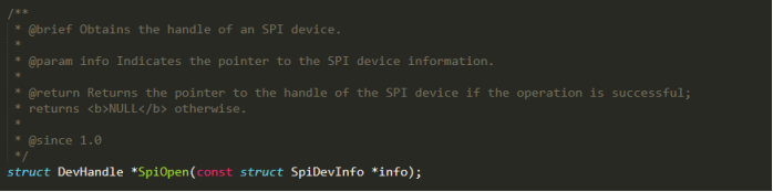
鸿蒙OS中关于spi接口的定义在源码目录: \drivers\hdf\frameworks\include\platform\ \drivers\hdf\frameworks\support\platform\src 下的 spi_if.h和spi_if.c文件中。 1.打开SPI设备
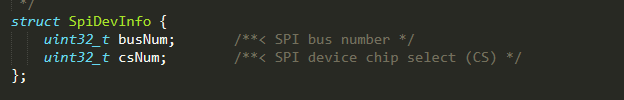
其中info为指向SPI设备信息的指针,其类型在h头文件中有如下定义:
busNum 和 cdNum 分别为SPI设备号和片选号,本次课程中我们使用spi2。 2.关闭SPI设备
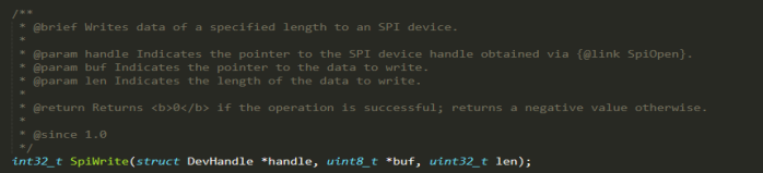
需要关闭spi设备时,调用该接口,传参需要关闭的spi设备句柄即可。 3.SPI写数据接口
该接口用于实现spi写数据操作,其中buf为指向要写入数据的指针,len为写入数据的长度。 4.SPI读数据接口
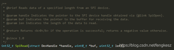
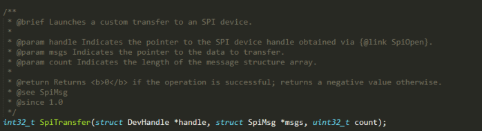
该接口用于实现spi读数据操作,其中buf为指向存储读取数据的指针,len为读取的数据的长度。 5.自定义SPI传输
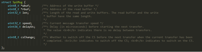
msgs为自定义传输消息结构体,count为消息长度,msgs的类型在头文件中有如下描述:
wbuf为指向写入数据的指针,rbuf为指向存储读取数据的buf的指针,len为读取和写入数据的长度,读写长度一致,speed为数据传输速度,delayUs为数据传输间隔,csChange指定是否在进行下一次传输前关闭片选。 6.SPI设备配置接口
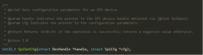
SpiCfg为当前SPI设备配置信息结构体,在头文件中定义如下:
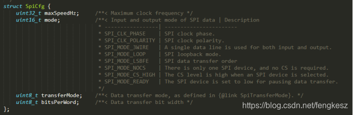
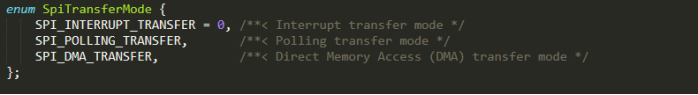
macSpwwdHz为最大SPI通信时钟频率,mode为输入输出通信模式,用预设值时钟极性等信息,transferMode为数据传输模式,在头文件中有定义如下:
bitsPerWord用于设置数据传输位宽。
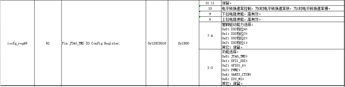
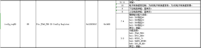
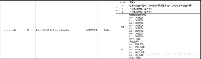
本次课程使用SPI1,其中MOSI管脚为GPIO1_7,SCLK管脚为GPIO1_5,MISO管脚为GPIO1_6,这三个管脚在海思的文档中有如下说明:
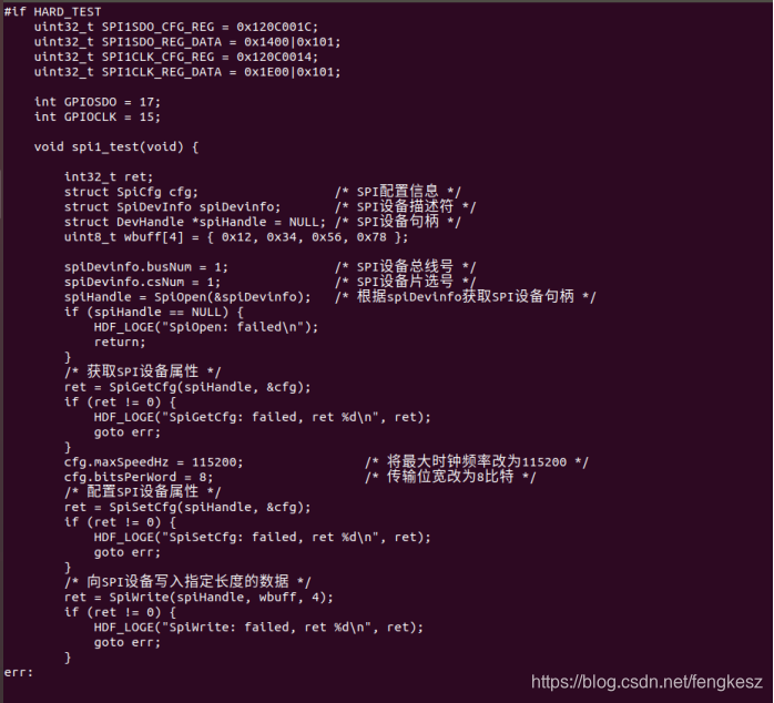
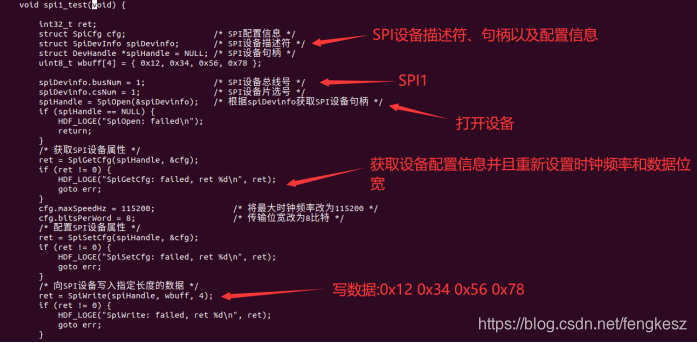
关于GPIO初始化部分的代码和HDF框架的代码本次课程不再做介绍。 对于SPI,驱动修改如下:
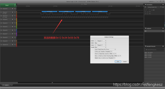
运行结果:
通过逻辑分析仪抓波。 欢迎加入疯壳学习交流QQ群457586268 |
共3条
1/1 1 跳转至页
疯壳-鸿蒙OS-总线驱动开发及实现之SPI
只看楼主 1楼


关键词: 鸿蒙OS 疯壳
共3条
1/1 1 跳转至页
回复
 我要赚赏金打赏帖 我要赚赏金打赏帖 |
|
|---|---|
| 片外存储Flash使用方法(Arduino IDE环境)被打赏¥22元 | |
| 三分钟快速上手ESP-NOW(ArduinoIDE环境)被打赏¥23元 | |
| 【S32K3XX】LPSPI参数配置说明被打赏¥21元 | |
| 在WT9932C61-TINY上实现超声波测距被打赏¥22元 | |
| 基于WT9932C61-TINY的环境构建及OLED屏驱动测试被打赏¥20元 | |
| 【S32K3XX】Core-to-Core 中断使用被打赏¥21元 | |
| 「AI编程记录--含源码」用一晚上的时间写一个esp32的示波器被打赏¥19元 | |
| STM32C0116DK开发探索记(3)被打赏¥30元 | |
| STM32C0116DK开发探索记(2)被打赏¥24元 | |
| STM32C0116DK开发探索记(1)被打赏¥29元 | |
 STM32
STM32 MCU
MCU 通讯及无线技术
 物联网技术
物联网技术 电子DIY
电子DIY 板卡试用
板卡试用 基础知识
基础知识 软件与操作系统
 我爱生活
我爱生活 小e食堂
小e食堂

