
还有要注意的是当两台机器其中1台未通电或双绞线未接通,这时是测试不到输出波形的。
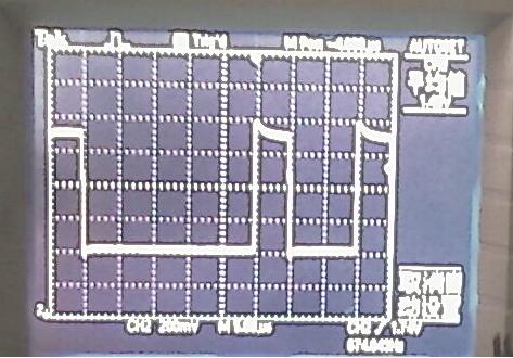
图1 CAN接口正常的波形
一手按快门,一手按发送按键,照片抖动厉害,看不很清楚,示波器放在垂直200mV/格,水平5uS/格。当你能看到这样的波形时,起码刚发送的这台机器发送功能是正常的,且2台机的通信节点也连通了。
ARM DIY进程11:USB虚拟鼠标
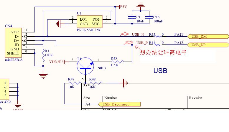
练习利用开发板上的USB接口实现免驱动鼠标功能,免驱动鼠标属于人机交互设备HID。本次练习需要4只按键实现鼠标光标上下左右移动,开发板上的按键接口太少,只好在板外另外搭接4只按键使用,见图1。在开发板上“USB_Disconnect”通过JP2连接到GPIOA_10注明缺省状态为“Open”,此时T1(9013)由于B极0偏置故C-E极截至,USB接口第3脚D+将为0V,PC机将认不到插入的USB设备。所以要么将JP2短接,并在程序中设PA10为输出口并输出高电平,要么直接将R47接JP2端连接到3.3V或干脆将T1的C-E极直接短路来调试(图3)。
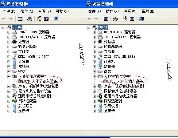
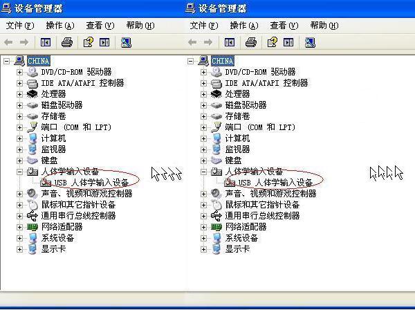
说实在话,这个USB从底层一直到用户层,实在是太复杂了,要弄通它不是几个练习就可以做到的。本次练习只不过是发挥了DIY者的的特长:COPY+PASTE东拼西凑完成的,详细原理在此就不敢班门弄斧了。从ST官方网站下载的MDK例程JoStickMouse在开发板上都无法成功运行。本例程是移植了ST官方IAR的例程的。运行后仿真环境就无法进入DEBUG跟踪、断点了。当虚拟鼠标USB设备被PC识别后,在WindowsXP设备管理器里会增加一个USB人体学输入设备(图4图5),这时按UP、DN、RIGTH、LEFT其中一键屏幕上的鼠标会朝不同方向移动,移动的速度可在"HW_CONFIG.H"头文件的CURSOR_STEP变量中重新定义。有时侯增加的USB人体学输入设备会出现黄色问号警告,只要拔去USB连接线,把这个设备卸载,然后重新插上USB连接线,系统就会自动安装新设备正常工作了。
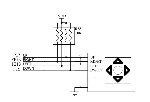
图1
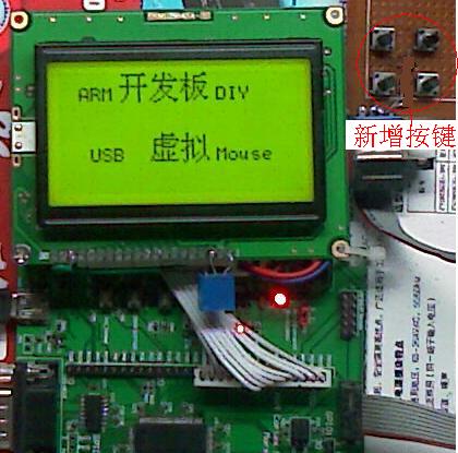
图2
关键代码
"hw_config.c"
#include "STM32Lib\\stm32f10x.h"
#include "hw_config.h"
#include "STM32Lib\\usblib\\usb_lib.h"
#include "usb_desc.h"
#include "platform_config.h"
#include "usb_pwr.h"
ErrorStatus HSEStartUpStatus;
EXTI_InitTypeDef EXTI_InitStructure;
void Set_System(void)
{
GPIO_InitTypeDef GPIO_InitStructure;
SystemInit();
RCC_APB1PeriphClockCmd(RCC_APB1Periph_PWR, ENABLE);
GPIO_AINConfig();
RCC_APB2PeriphClockCmd(RCC_APB2Periph_GPIO_DISCONNECT, ENABLE);
/* USB_DISCONNECT used as USB pull-up */
GPIO_InitStructure.GPIO_Pin = USB_DISCONNECT_PIN;
GPIO_InitStructure.GPIO_Speed = GPIO_Speed_2MHz;
GPIO_InitStructure.GPIO_Mode = GPIO_Mode_Out_PP;
GPIO_Init(USB_DISCONNECT, &GPIO_InitStructure);
/* Enable Joystick GPIOs clock */
RCC_APB2PeriphClockCmd(RCC_APB2Periph_GPIO_JOY_SET1, ENABLE);
RCC_APB2PeriphClockCmd(RCC_APB2Periph_GPIO_JOY_SET2, ENABLE);
/* Configure the JoyStick IOs */这里配置IO口的方法又有新意
GPIO_InitStructure.GPIO_Pin = GPIO_Pin_UP;
GPIO_InitStructure.GPIO_Mode = GPIO_Mode_IPU;
GPIO_Init(GPIO_UP, &GPIO_InitStructure);
GPIO_InitStructure.GPIO_Pin = GPIO_Pin_DOWN;
GPIO_Init(GPIO_DOWN, &GPIO_InitStructure);
GPIO_InitStructure.GPIO_Pin = GPIO_Pin_LEFT;
GPIO_Init(GPIO_LEFT, &GPIO_InitStructure);
GPIO_InitStructure.GPIO_Pin = GPIO_Pin_RIGHT;
GPIO_Init(GPIO_RIGHT, &GPIO_InitStructure);
/* Enable GPIOB & AFIO clocks */
RCC_APB2PeriphClockCmd(RCC_APB2Periph_GPIO_KEY | RCC_APB2Periph_AFIO, ENABLE);
/* Configure the Key pin as input floating */ /* used for remote wakeup */
GPIO_InitStructure.GPIO_Pin = GPIO_Pin_KEY;
GPIO_InitStructure.GPIO_Mode = GPIO_Mode_IN_FLOATING;
GPIO_Init(GPIO_KEY, &GPIO_InitStructure);
GPIO_EXTILineConfig(GPIO_KEY_PORTSOURCE, GPIO_KEY_PINSOURCE); /* Connect EXTI Line9 */
EXTI_InitStructure.EXTI_Line = GPIO_KEY_EXTI_Line; /* Configure EXTI Line9 to generate an interrupt on falling edge */
EXTI_InitStructure.EXTI_Mode = EXTI_Mode_Interrupt;
EXTI_InitStructure.EXTI_Trigger = EXTI_Trigger_Falling;
EXTI_InitStructure.EXTI_LineCmd = ENABLE;
EXTI_Init(&EXTI_InitStructure);
/* used for USB resume interrupt */
EXTI_ClearITPendingBit(EXTI_Line18);
EXTI_InitStructure.EXTI_Line = EXTI_Line18;
EXTI_InitStructure.EXTI_Trigger = EXTI_Trigger_Rising;
EXTI_InitStructure.EXTI_LineCmd = ENABLE;
EXTI_Init(&EXTI_InitStructure);
EXTI_ClearITPendingBit(GPIO_KEY_EXTI_Line);
}
/*******************************************************************************
* Function Name : Set_USBClock
* Description : Configures USB Clock input (48MHz).
* Input : None.
* Output : None.
* Return : None.
*******************************************************************************/
void Set_USBClock(void)
{
/* Select USBCLK source */
RCC_USBCLKConfig(RCC_USBCLKSource_PLLCLK_1Div5);
/* Enable USB clock */
RCC_APB1PeriphClockCmd(RCC_APB1Periph_USB, ENABLE);
}
/*******************************************************************************
* Function Name : GPIO_AINConfig
* Description : Configures all IOs as AIN to reduce the power consumption.
* Input : None.
* Output : None.
* Return : None.
*******************************************************************************/
void GPIO_AINConfig(void)
{
GPIO_InitTypeDef GPIO_InitStructure;
/* Enable all GPIOs Clock*/
RCC_APB2PeriphClockCmd(RCC_APB2Periph_ALLGPIO, ENABLE);
/* Configure all GPIO port pins in Analog Input mode (floating input trigger OFF) */
GPIO_InitStructure.GPIO_Pin = GPIO_Pin_All;
GPIO_InitStructure.GPIO_Mode = GPIO_Mode_AIN;
GPIO_Init(GPIOA, &GPIO_InitStructure);
GPIO_Init(GPIOB, &GPIO_InitStructure);
GPIO_Init(GPIOC, &GPIO_InitStructure);
GPIO_Init(GPIOD, &GPIO_InitStructure);
GPIO_Init(GPIOE, &GPIO_InitStructure);
/* Disable all GPIOs Clock*/
RCC_APB2PeriphClockCmd(RCC_APB2Periph_ALLGPIO, DISABLE);
}
/*******************************************************************************
* Function Name : Enter_LowPowerMode.
* Description : Power-off system clocks and power while entering suspend mode.
* Input : None.
* Output : None.
* Return : None.
*******************************************************************************/
void Enter_LowPowerMode(void)
{
/* Set the device state to suspend */
bDeviceState = SUSPENDED;
/* Clear EXTI Line18 pending bit */
EXTI_ClearITPendingBit(GPIO_KEY_EXTI_Line);
/* Request to enter STOP mode with regulator in low power mode */
PWR_EnterSTOPMode(PWR_Regulator_LowPower, PWR_STOPEntry_WFI);
}
/*******************************************************************************
* Function Name : Leave_LowPowerMode.
* Description : Restores system clocks and power while exiting suspend mode.
* Input : None.
* Output : None.
* Return : None.
*******************************************************************************/
void Leave_LowPowerMode(void)
{
DEVICE_INFO *pInfo = &Device_Info;
/* Enable HSE */
RCC_HSEConfig(RCC_HSE_ON);
/* Wait till HSE is ready */
HSEStartUpStatus = RCC_WaitForHSEStartUp();
/* Enable PLL */
RCC_PLLCmd(ENABLE);
/* Wait till PLL is ready */
while (RCC_GetFlagStatus(RCC_FLAG_PLLRDY) == RESET)
{}
/* Select PLL as system clock source */
RCC_SYSCLKConfig(RCC_SYSCLKSource_PLLCLK);
/* Wait till PLL is used as system clock source */
while (RCC_GetSYSCLKSource() != 0x08)
{}
/* Set the device state to the correct state */
if (pInfo->Current_Configuration != 0)
{
/* Device configured */
bDeviceState = CONFIGURED;
}
else
{
bDeviceState = ATTACHED;
}
}
/*******************************************************************************
* Function Name : USB_Interrupts_Config.
* Description : Configures the USB interrupts.
* Input : None.
* Output : None.
* Return : None.
*******************************************************************************/
void USB_Interrupts_Config(void)
{
NVIC_InitTypeDef NVIC_InitStructure;
/* 2 bit for pre-emption priority, 2 bits for subpriority */
NVIC_PriorityGroupConfig(NVIC_PriorityGroup_2);
/* Enable the USB interrupt */
NVIC_InitStructure.NVIC_IRQChannel = USB_LP_CAN1_RX0_IRQn;
NVIC_InitStructure.NVIC_IRQChannelPreemptionPriority = 1;
NVIC_InitStructure.NVIC_IRQChannelSubPriority = 1;
NVIC_InitStructure.NVIC_IRQChannelCmd = ENABLE;
NVIC_Init(&NVIC_InitStructure);
/* Enable the USB Wake-up interrupt */
NVIC_InitStructure.NVIC_IRQChannel = USBWakeUp_IRQn;
NVIC_InitStructure.NVIC_IRQChannelPreemptionPriority = 0;
NVIC_InitStructure.NVIC_IRQChannelSubPriority = 0;
NVIC_InitStructure.NVIC_IRQChannelCmd = ENABLE;
NVIC_Init(&NVIC_InitStructure);
/* Enable the Key EXTI line Interrupt */
NVIC_InitStructure.NVIC_IRQChannel = EXTI_KEY_IRQChannel;
NVIC_InitStructure.NVIC_IRQChannelPreemptionPriority = 2;
NVIC_InitStructure.NVIC_IRQChannelSubPriority = 0;
NVIC_InitStructure.NVIC_IRQChannelCmd = ENABLE;
NVIC_Init(&NVIC_InitStructure);
}
/*******************************************************************************
* Function Name : USB_Cable_Config.
* Description : Software Connection/Disconnection of USB Cable.
* Input : NewState: new state.
* Output : None.
* Return : None
*******************************************************************************/
void USB_Cable_Config (FunctionalState NewState)
{
if (NewState == DISABLE)
{
GPIO_ResetBits(USB_DISCONNECT, USB_DISCONNECT_PIN);
}
else
{
GPIO_SetBits(USB_DISCONNECT, USB_DISCONNECT_PIN);
}
}
/*******************************************************************************
* Function Name : JoyState.
* Description : Decodes the Joystick direction.
* Input : None.
* Output : None.
* Return value : The direction value.
*******************************************************************************/
uint8_t JoyState(void)
{
/* "right" key is pressed */
if (!GPIO_ReadInputDataBit(GPIO_RIGHT, GPIO_Pin_RIGHT))
{
return RIGHT;
}
/* "left" key is pressed */
if (!GPIO_ReadInputDataBit(GPIO_LEFT, GPIO_Pin_LEFT))
{
return LEFT;
}
/* "up" key is pressed */
if (!GPIO_ReadInputDataBit(GPIO_UP, GPIO_Pin_UP))
{
return UP;
}
/* "down" key is pressed */
if (!GPIO_ReadInputDataBit(GPIO_DOWN, GPIO_Pin_DOWN))
{
return DOWN;
}
/* No key is pressed */
else
{
return 0;
}
}
/*******************************************************************************
* Function Name : Joystick_Send.
* Description : prepares buffer to be sent containing Joystick event infos.
* Input : Keys: keys received from terminal.
* Output : None.
* Return value : None.
*******************************************************************************/
void Joystick_Send(uint8_t Keys)
{
uint8_t Mouse_Buffer[4] = {0, 0, 0, 0};
int8_t X = 0, Y = 0;
switch (Keys)
{
case LEFT:
X -= CURSOR_STEP;
break;
case RIGHT:
X += CURSOR_STEP;
break;
case UP:
Y -= CURSOR_STEP;
break;
case DOWN:
Y += CURSOR_STEP;
break;
default:
return;
}
/* prepare buffer to send */
Mouse_Buffer[1] = X;
Mouse_Buffer[2] = Y;
/*copy mouse position info in ENDP1 Tx Packet Memory Area*/
UserToPMABufferCopy(Mouse_Buffer, GetEPTxAddr(ENDP1), 4);
/* enable endpoint for transmission */
SetEPTxValid(ENDP1);
}
/*******************************************************************************
* Function Name : Get_SerialNum.
* Description : Create the serial number string descriptor.
* Input : None.
* Output : None.
* Return : None.
*******************************************************************************/
void Get_SerialNum(void)
{
uint32_t Device_Serial0, Device_Serial1, Device_Serial2;
Device_Serial0 = *(uint32_t*)(0x1FFFF7E8);
Device_Serial1 = *(uint32_t*)(0x1FFFF7EC);
Device_Serial2 = *(uint32_t*)(0x1FFFF7F0);
if (Device_Serial0 != 0)
{
Joystick_StringSerial[2] = (uint8_t)(Device_Serial0 & 0x000000FF);
Joystick_StringSerial[4] = (uint8_t)((Device_Serial0 & 0x0000FF00) >> 8);
Joystick_StringSerial[6] = (uint8_t)((Device_Serial0 & 0x00FF0000) >> 16);
Joystick_StringSerial[8] = (uint8_t)((Device_Serial0 & 0xFF000000) >> 24);
Joystick_StringSerial[10] = (uint8_t)(Device_Serial1 & 0x000000FF);
Joystick_StringSerial[12] = (uint8_t)((Device_Serial1 & 0x0000FF00) >> 8);
Joystick_StringSerial[14] = (uint8_t)((Device_Serial1 & 0x00FF0000) >> 16);
Joystick_StringSerial[16] = (uint8_t)((Device_Serial1 & 0xFF000000) >> 24);
Joystick_StringSerial[18] = (uint8_t)(Device_Serial2 & 0x000000FF);
Joystick_StringSerial[20] = (uint8_t)((Device_Serial2 & 0x0000FF00) >> 8);
Joystick_StringSerial[22] = (uint8_t)((Device_Serial2 & 0x00FF0000) >> 16);
Joystick_StringSerial[24] = (uint8_t)((Device_Serial2 & 0xFF000000) >> 24);
}
}
"platform_config.h"
#ifndef __PLATFORM_CONFIG_H
#define __PLATFORM_CONFIG_H
used to run the example */
#define USB_DISCONNECT GPIOA
#define USB_DISCONNECT_PIN GPIO_Pin_8
#define RCC_APB2Periph_GPIO_DISCONNECT RCC_APB2Periph_GPIOA
#define RCC_APB2Periph_GPIO_KEY RCC_APB2Periph_GPIOB
#define GPIO_Pin_KEY GPIO_Pin_11 //按键口在这里定义
#define GPIO_Pin_UP GPIO_Pin_6
#define GPIO_Pin_DOWN GPIO_Pin_7
#define GPIO_Pin_LEFT GPIO_Pin_13
#define GPIO_Pin_RIGHT GPIO_Pin_15
#define RCC_APB2Periph_GPIO_JOY_SET1 RCC_APB2Periph_GPIOC
#define RCC_APB2Periph_GPIO_JOY_SET2 RCC_APB2Periph_GPIOB
#define GPIO_RIGHT GPIOC
#define GPIO_LEFT GPIOC
#define GPIO_DOWN GPIOA
#define GPIO_UP GPIOC
#define GPIO_KEY GPIOB
#define GPIO_KEY_PORTSOURCE GPIO_PortSourceGPIOB
#define GPIO_KEY_PINSOURCE GPIO_PinSource7
#define GPIO_KEY_EXTI_Line EXTI_Line7
#define EXTI_KEY_IRQChannel EXTI9_5_IRQn
#define RCC_APB2Periph_ALLGPIO (RCC_APB2Periph_GPIOA \
| RCC_APB2Periph_GPIOB \
| RCC_APB2Periph_GPIOC \
| RCC_APB2Periph_GPIOD \
| RCC_APB2Periph_GPIOE )
#endif /* __PLATFORM_CONFIG_H */
| 有奖活动 | |
|---|---|
| 2026年“我要开发板活动”第三季,开始了! | |
| 硬核工程师专属补给计划——填盲盒 | |
| “我踩过的那些坑”主题活动——第002期 | |
| 【EEPW电子工程师创研计划】技术变现通道已开启~ | |
| 发原创文章 【每月瓜分千元赏金 凭实力攒钱买好礼~】 | |
| 【EEPW在线】E起听工程师的声音! | |
| 高校联络员开始招募啦!有惊喜!! | |
| 【工程师专属福利】每天30秒,积分轻松拿!EEPW宠粉打卡计划启动! | |
 我要赚赏金打赏帖 我要赚赏金打赏帖 |
|
|---|---|
| PTC与NTC功能常规对比被打赏¥14元 | |
| 【分享开发笔记,赚取电动螺丝刀】关于3pin锂电池接口的介绍/使用被打赏¥16元 | |
| 以启明云端ESP32P4开发板实现TF卡读写功能被打赏¥28元 | |
| 【分享开发笔记,赚取电动螺丝刀】树莓派5串口UART0配置被打赏¥25元 | |
| 【STM32F103ZET6】17:分享在Rtos项目中断管理的使用经验被打赏¥23元 | |
| 【STM32F103ZET6】16:分享在中断中恢复串口任务,遇到的问题被打赏¥31元 | |
| 在FireBeetle2ESP32-C5上实现温度大气压检测及显示被打赏¥21元 | |
| 【分享开发笔记,赚取电动螺丝刀】SAME51双串口收发配置被打赏¥27元 | |
| Chaos-nano操作系统在手持式VOC检测设备上的应用被打赏¥37元 | |
| 【分享开发笔记,赚取电动螺丝刀】关于在导入第三方库lib时,wchart类型冲突的原因及解决方案被打赏¥30元 | |
 STM32
STM32 MCU
MCU 通讯及无线技术
 物联网技术
物联网技术 电子DIY
电子DIY 板卡试用
板卡试用 基础知识
基础知识 软件与操作系统
 我爱生活
我爱生活 小e食堂
小e食堂

