
Voyager M3i
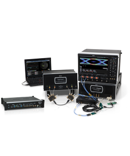
The Voyager M3 is LeCroy’s 6th generation USB protocol verification platform designed for the next evolution of universal serial bus known as SuperSpeed USB. Leveraging LeCroy’s extensive expertise in high-speed serial data analysis, the Voyager provides 100% accurate protocol capture of both USB 2.0 and 3.0 at data rates up to 5 Gb/s.
LeCroy has developed six generations of its industry leading USB protocol verification system since the introduction of USB in 1995. Each successive generation of the LeCroy USB analyzer family has built upon the previous knowledge and expertise. Today, LeCroy offers a broad range of USB test systems with unprecedented functionality, accuracy and user friendliness. The enormous cost of discovering problems after a product is released far outweighs the investment in LeCroy's de-facto standard USB analysis tools. Their use improves the speed and efficiency of the debug, test and verification for USB semiconductor, device, and software vendors. Analyzers or bus "sniffers" also play an essential role in avoiding costly interoperability problems by allowing developers to verify compliance with the USB specification.
Consistent with the growing popularity of digital media, the USB-IF announced USB 3.0 in late 2007 targeting 10X the current USB bandwidth by utilizing two additional high-speed differential pairs for "SuperSpeed" transfer mode. The USB 3.0 specification was released in late 2008 and commercial products began shipping in late 2009. LeCroy has pioneered the development of verifications systems for this new technology. The only company that offers a complete line of USB 3.0 test solutions covering transmitter test to protocol test, and every step in between, LeCroy helps developers achieve their goals of performance, quality, reliability and time-to-market for SuperSpeed technology.
USB Technology Overview:USB, or Universal Serial Bus, is a connectivity standard that enables computer peripherals and consumer electronics to be connected to a computer without reconfiguring the system or opening the computer box to install interface cards. The USB 1.0 specification was introduced in January 1996. The original USB 1.0 specification had a data transfer rate of 12 Mbit/s The first widely used version of USB was 1.1, which was released in September 1998. It provided 12 Mbps data rate for higher-speed devices such as disk drives, and a lower 1.5 Mbps rate for low bandwidth devices such as joysticks. USB 2.0 specification was released in April 2000 and was ratified by the USB-IF at the end of 2001 to develop a higher data transfer rate, with the resulting specification achieving 480 Mbit/s
USB today provides a fast, bi-directional, low-cost, serial interface that offers easy connectivity to PCs. A hallmark for USB operation has been the ability for the host to automatically recognize devices as they are attached and install the appropriate drivers. With features such as backward compatibility with previous devices and hot "plug-ability", USB has become the de-facto standard interface for various consumer and PC peripheral devices. The USB standard allows up to 127 devices connected to a Host System. USB designates low, full, high-speed connectivity between devices compatible with the 2.0 specification. Most full speed devices include lower bandwidth mice, keyboards, printers, and joysticks. The use of high speed USB has exploded with the rapid growth in digital media in the consumer electronics market including media players, digital cameras, external storage and smart phones.
SuperSpeed USB is designator for links operating at the 5 GHz frequency and compatible with the USB 3.0 specification. SuperSpeed USB provides a high performance connection topology for applications that utilize larger files or require higher bandwidth. SuperSpeed USB is backward compatible with USB 2.0, resulting in a seamless transition process for the end user. SuperSpeed USB offers a compelling opportunity for digital imaging and media device vendors to migrate their designs to higher performance USB 3.0 capable interface.
NEC/Renesas was the first chip vendor to introduce host controllers for USB 3.0 (5/18/2009). The first motherboards featuring USB 3.0 ports from Asus and Gigabyte followed in late 2009. In the first half of 2010, dozens of SuperSpeed devices began shipping as vendors rushed to deliver solutions using the 5Gbps signaling speed of USB 3.0. Expect mass adoption into high-bandwidth applications in late 2010.
Why USB?From its emergence in 1995 as a low-cost connection interface for keyboards and mice, USB has steadily expanded its presence in computing and consumer electronics to become the most popular peripheral interconnect in history. USB continues to be dominant for the following reasons:
- Mature, proven technology
- Backward-compatible and low cost
- Easy plug and play operation
- Data transfer speeds suitable for a variety of applications
As evidenced by USB popularity, several extensions of the technology have been introduced to try and capitalize on its installed base/ popularity. An example of this extension, which is supported and approved by the USB Implementers Forum (USB-IF), is USB On-The-Go (OTG). Designed to allow portable computing devices, such as cell phones and digital cameras, the ability to connect to other USB devices as either a host or peripheral, OTG promises improved interoperability for an enormous number of USB enabled devices.
In addition, there are now dozens of USB device classes addressing everything from health care systems to isochronous video applications. Mass storage remains one of the most popular USB applications as consumers have embraced all types of digital media. The T10 committee has now finalized USB Attached SCSI (UAS) protocol which enables several significant improvements over legacy mass storage protocols including command queuing and streamed IO. Of particular interest is the new battery charging specification which provides a standard mechanism allowing devices to draw current in excess of the USB specification when connected to wall chargers or fast charging host controllers. In addition to the traditional data interchange application, the battery charging specification has solidified USB's dominant role as the interface of choice in the portable electronics market.
USB ArchitectureUSB was initially introduced as a host to peripheral interconnect with the goal of putting most of the intelligence on the host-side. The OTG specification added an optional peer-to-peer capability to devices but had limited adoption to date. So the vast majority of USB devices typically fall into 2 categories:
- Hosts
- PCs, Macs and laptops
- Peripherals
- All devices designed to attach to a host (examples)
The role of the host controller (plus software) is to provide a uniform view of IO systems for all applications software. For the USB IO subsystem in particular, the host manages the dynamic attach and detach of peripherals. It automatically performs the enumeration stage of device initialization which involves communicating with the peripheral to discover the identity of a device driver that it should load, if not already loaded. It also provides device descriptor information that drivers can use enable specific features on the device. Peripherals add functionality to the host system or may be standalone embedded operation. When operating as a USB device, peripherals act are slaves that obey a defined protocol. They must react to requests sent from the host. It's largely the role of PC software to manage device power without user interaction to minimize overall power consumption. The USB 3.0 specification redefines power management to occur at the hardware level with multiple power states designed to reduce power usage across the IO system.
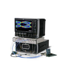
LinksThe Voyager M3 is LeCroy’s 6th generation USB protocol verification system designed for the next evolution of universal serial bus known as SuperSpeed USB. Leveraging LeCroy’s extensive expertise in high-speed serial data analysis, the Voyager provides 100% accurate protocol capture of both USB 2.0 and 3.0 at data rates up to 5 Gb/s.
This multifunction validation platform is available with an integrated exerciser capable of both 2.0 and 3.0 host and device emulation. In addition to error injection and compliance verification, the exerciser provides early adopters with a USB 3.0 link to begin bring-up testing well before commercial hosts are available. Loaded with innovative features that anticipate the needs of early adopters, the Voyager platform is the intelligent choice for "cradle-to-grave" USB 3.0 validation.
Voyager USB 3.0 Introduction series of video demos


Unmatched Accuracy
The Voyager analyzer front-end leverages custom circuitry from LeCroy’s 5Gb/s PCI Express analyzer to provide fast-locking and uncompromised accuracy for USB 3.0 recording. SuperSpeed USB will implement hardware based power management with devices frequently entering power suspend mode. While in-line, the Voyager system will detect and seamlessly recover from electrical idle while accurately showing all bus and power state transitions time-stamped within the display. It includes full support for spread spectrum clocking (SSC) and data scrambling (LFSR) which can be enabled / disabled for silicon bring-up testing.
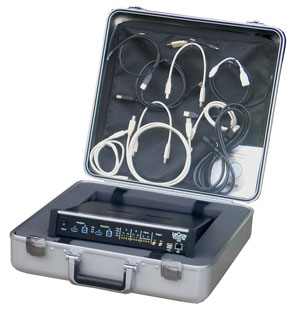
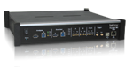
Flexible hardwareThe front end of the Voyager analyzer features native 3.0 connectors that bifurcate USB 2.0 and 3.0 electrical signals to provide loss-less capture of traffic from both links simultaneously. Concurrent high-speed and SuperSpeed recording allows end-to-end viewing of data transfers across a USB 3.0 hub. The system can operate as a USB 2.0/3.0 analyzer; and is also available in a 2.0-only configuration that is upgradeable to 3.0.
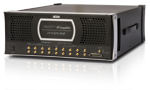
The Voyager M3 platform includes 4GB of recording memory plus USB and Gbe links for uploading recorded traffic to the host PC. Fast access to captured traffic is now possible thanks to sustained data transfers of 600Mbit per second over the Gbe link. Both the analyzer and exerciser can utilize slow clocking (fractional) or external clock sources (as low as 1Mhz) for testing with FPGA-based prototypes or emulators that require ultra low-speed data acquisition. More
The heart of the Voyager verification system is LeCroy’s revolutionary BusEngine? technology. This state-of-the-art protocol processing core incorporates a real-time recording engine and configurable tools to selectively monitor and record SuperSpeed USB traffic. Field upgradeable firmware allows the BusEngine to evolve and support new features or future changes to the USB specification.
Additional innovations include upgradeable hardware components. The USB connectors on the analyzer are mounted on a removable daughter-card allowing the system to be upgraded as improved connectors are available. The analyzer and exerciser also include SMA differential Input/Output lines as an alternate interface for taping between early development boards. This eliminates dependencies on USB 3.0 connectors allowing testing to begin as soon as PHY silicon is available.
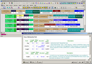
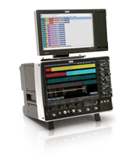
6th Generation Analysis SoftwareThe Voyager utilizes the legendary CATC Trace which has become the industry’s de facto standard for USB 2.0 protocol analysis. The trace viewer software uses colors and patterns to train the eye to understand information faster. When recording mixed traffic upstream from a SuperSpeed hub, Legacy 2.0 and 3.0 packets are labeled and interleaved in a single display. Each event is shown on a separate row with every field labeled and color coded.. Traffic from the logical 2.0 & 3.0 channels can be individually filtered, searched or exported from the trace. The USB Transfer level can be expanded and collapsed to show the packet layer including all link management packets (LMPs) and flow control symbols.
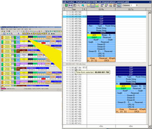
The Voyager includes a special Link Tracker mode that captures every transition and presents raw 10-bit data patterns chronologically with timing resolution of 2ns. Designed to assist with low-level debugging, all ordered sets including training sequences and inter-packet symbols can be displayed in raw 10-bit, 8-bit, scrambled, and unscrambled Hex format. Symbol-to-symbol timing measurements are possible with a single click.
- CATC Trace Analysis Software System ¨C Expand / Collapse transfer layer for faster interpretation of USB traffic
- Capture / Analyze 3.0 & 2.0 traffic concurrently ¨C Record 2.0 and SuperSpeed data path to test & debug USB 3.0 host & hub operation
- Integrated 3.0 analyzer / exerciser (single box) ¨C Multifunction system with 3.0 and 2.0 device or host traffic generation
- 4GB Recording Capacity - Capture long recording sessions for analysis and problem solving
- Raw bit Recording / 10-bit error detection ¨C view and correlate low-level 10-bit symbols to higher-level packet structures
- Detects over 40 Link & Protocol errors ¨C Critical link and timing errors are automatically detected and flagged in the trace
- 2ns timing resolution - extremely accurate timing resolution allows precise measurement of link layer handshaking
- External Trigger In / Out ¨C Use the LeCroy Voyager to identify any packet and toggle a scope or logic analyzer (via SMA connectors)
- Fully supports SSC and Data scrambling - Fast Locking and Accurate capture on 5Gbps signals
- Hardware Triggering ¨C Trigger on both 2.0 or 3.0 protocol events to isolate important traffic, specific errors or data patterns
- Comprehensive Device Decoding - SCSI Mass Storage, 3.0 Hub, PTP/Still Image, Printer, PictBridge, Media Transfer Protocol (MTP), and all popular USB device classes
- Hardware Filtering - Automatically exclude non-essential and redundant symbols including Idles, TS1, TS2, SKPs, and LFPS sequences.
- Intelligent Reporting - Automatically report event metrics and flag over 20 common USB 3.0 protocol errors
- Sophisticated Viewing - View TLP messages and headers, plus logical transaction and transfer layers of the USB protocol
- Gbe or Hi-Speed USB upload ¨C Sustained transfer rates of 600Mbps over Gbe provide instant access to captured data
- SMA-input differential probing - alternate connector interface allows taping between early development boards if native connectors are unavailable More
- Slow clock / External clock Input ¨C Adjustable signal frequencies for synchronizing analyzer timing with prototype & validation boards
- Loopback and Compliance Mode ¨C Exerciser system provides special console for initiating loopback and compliance mode
- Link Training and Timing Views - LTSSM flow diagram and chronological views linked to trace display
- Power Tracker? Option - Graphs Power & Current draw for VBus devices synchronized to the trace data
- 3 Year Hardware Warranty - Protect your investment with industry leading support and warranty
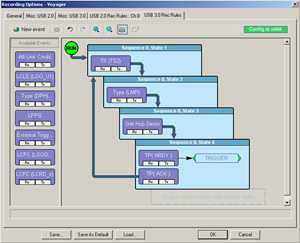
The Voyager provides hardware triggering to pinpoint protocol events of interest. Trigger events can be specified at the lowest levels including bus states and ordered sets (Link up, SKP, etc¡) or header fields including route strings or packet types (ACK, EPRDY, etc¡.). Voyager’s graphical drag-and-drop interface makes setup easy. Users can define trigger logic that monitors multiple sequential event trigger scenarios that include SCSI operations, counters, loops and timers all within a multi-level sequence.
SuperSpeed data transfers at 5 Gb/s can fill memory buffers in an instant making event filtering critical for efficient debug. The Voyager analyzer can filter unwanted traffic from the buffer in real-time by discarding redundant patterns such as SKPs, idles, and training sequences. Filtering logic can also include transaction layer packets with added criteria like direction or port number.
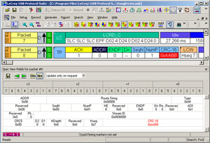
Error DetectionThe LeCroy Voyager can detect and flag real protocol errors including logical link and timing errors. At the lower layers, training sequences and link commands are automatically verified for proper formatting. The Spec View displays header fields in hex or binary and also marks errors in red.
A comprehensive exerciser capability with support for both USB 2.0 and 3.0 traffic generation is built in to the Voyager platform. The exerciser option allows users to transmit custom packets over standard USB cables with low-level control of headers, payloads, timing, and link states. Featuring Voyager ReadyLink? and Transaction Engine? the exerciser includes full function link and transaction layer state machines that automatically handle all USB 3.0 handshakes. ReadyLink maintains link synchronization, flow control and header acknowledgements. The Transaction Engine manages NRDY retry conditions allowing the Voyager to operate at full line rate and correctly respond to the DUT as defined by the specification. . Overrides allow these behaviors to be altered such as shortening LFPS and link training signals, or delaying handshake packets. The Exerciser is seamlessly integrated with the Protocol Analyzer, making the Voyager system a complete test and development solution for engineers validating USB protocol. More
USB Device DecodingThe Voyager software performs full decoding of USB device class traffic with both automatic and manual assignment of decodes to individual endpoints. The Voyager offers full support for Bulk Only Transport and USB Attached SCSI operations including command queuing. From OTG, to CCD, to Video class, Voyager provides the most comprehensive decoding available. It also supports vendor specific decoding for developers interested in automatically showing proprietary commands in the trace view.
Complete list of USB Decodes (Click to Expand ¡ý)- Mass Storage - SCSI (SPC-2)
- Mass Storage - ATAPI (MMC-2)
- Mass Storage - RBC (R10A)
- Hub Class
- Hub Notification
- Printer Class
- Communication Class
- Communication Notification
- Communication Class with AT Command
- Communication Class with PPP
- Bluetooth HCI Command
- Bluetooth HCI Event
- Bluetooth ACL Packet
- Bluetooth SCO Packet
- HID Class
- Audio Class Descriptor
- Audio Class Request
- CCID Class Request
- CCID - Command
- CCID - Event
- CCID - Data/Response
- CDC - HDLC - Command
- CDC - 1430 - Command
- CDC - Q931 - Command
- CDC - Q921M - Command
- CDC - Q921 - Command
- CDC - Trans - Command
- CDC - V.42bis - Command
- CDC - Event
- CDC - Class Descriptor
- CDC - Class Request
- Firmware - Class Request
- Firmware - Class Descriptor
- HID Class Descriptor
- HID Class Request
- Mass Storage Class Request
- MTP - Class Req.
- MTP - Command
- MTP - Data/Resp.
- MTP - Event
- PPP - Ethernet Receive
- PPP - Ethernet Send
- SCSI- MMC4 - Bulk Only
- SCSI - MMC4 - CBI
- SCSI - RBC - CBI
- SCSI - SBC - Bulk Only
- SCSI - SBC - CBI
- SCSI - SPC2- CBI
- SCSI - SPC3 - Bulk Only
- SCSI - SPC3 - CBI
- SCSI - SSC - Bulk Only
- SCSI - SSC - CBI
- Still Image (Cmd.Data. Resp)
- Still Image Class Req.
- Still Image Command
- Still Image Data/Response
- Still Image Event
- USB Attached SCSI Protocol (UASP)
- USBTMC - Command
- USBTMC - Response
- USBTMC - Event
- Video - Cameras Terminal - Class Req.
- Video - Video Streaming - Class Req.
- Video - Descriptor
- Video - Event
- Video Payload Descriptor
- Video Payload
- Video Processing Units - Class Request
- Video Selector Units - Class Req.
- Video Transport
- Video - Video Control Interface - Class Req.
- WUSB - DWA - Descriptor
- WUSB - HWA - Descriptor
- WUSB - HWA - DWA Request
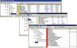
The Voyager software provides many mechanisms to measure and report on USB 2.0 and 3.0 protocol. With the Traffic Summary display, users can evaluate statistical reports at a glance or navigate to individual events. Users may select transaction packets to view ACK/NAK or Device Notification events, then jump to each occurrence with a single keystroke. Reports are available showing link throughput and flow control metrics. Higher level events are also tracked and reported at the logical USB Transfer level. The error report shows a range of protocol violations - from invalid CRCs to framing errors.
The LTSSM View provides an interactive USB 3.0 state machine diagram. Each state change is shown graphically and is hyperlinked to the trace display. The link state timing view shows the same information in a time-line format.
Bus Utilization graphs show data and packet length, bus usage by device in a histogram format. The Bandwidth calculator automatically calculates the time delta between two points in the trace. Fast Search and Find options allow users to navigate to specific packets, errors and any data type within a trace file. The CATC Trace supports filter and hide commands, to temporarily remove irrelevant data from the display for more efficient viewing.

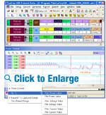
The Voyager M3i Power Tracker option offers a unique monitoring capability for Vbus power draw. Power information is sampled and displayed graphically in a time line format and is synchronized to the trace allowing users to verify power state transitions at the protocol and electrical layers. More
Since 1996, LeCroy has been a key provider of tools for the USB ecosystem. The Voyager system leverages countless hours of research in high-speed serial data analysis to create the most reliable and accurate USB 3.0 analyzer system available. Combined with the exerciser option and the CATC Trace expert software, the Voyager platform alleviates developers from tedious byte-level analysis and lets them focus on quick resolution of protocol layer problems.
 我要赚赏金
我要赚赏金 STM32
STM32 MCU
MCU 通讯及无线技术
 物联网技术
物联网技术 电子DIY
电子DIY 板卡试用
板卡试用 基础知识
基础知识 软件与操作系统
 我爱生活
我爱生活 小e食堂
小e食堂

