
很不错的呀 2013第一天依然在开发进程
43楼
进程17、LCD数字时钟
将1602LCD组合到DS1302数字时钟模块中,实现LCD数字时钟+LED数字时钟。
顶层模块:
module DS1302(
CLK, RSTn,
SEG, DIG,
RST,
SCLK,
SIO,
SEC_Data,
MIN_Data,
HOU_Data,
LED,
YELLOW,
lcd_rs,
lcd_rw,
lcd_en,
lcd_data,
);
input CLK;
input RSTn;
input [7:0]KEY;
output [7:0]SEG;
output [7:0]DIG;
output RST;
output SCLK;
inout SIO;
output [7:0]SEC_Data;
output [7:0]MIN_Data;
output [7:0]HOU_Data;
output [7:0]LED;
output [2:0]YELLOW;
wire [3:0]Data7;
wire [3:0]Data6;
wire [3:0]Data5;
wire [3:0]Data4;
wire [3:0]Data3;
wire [3:0]Data2;
wire [3:0]Data1;
wire [3:0]Data0;
//------------------------------------------------------------
output lcd_rs ;
output lcd_rw ;
output lcd_en ;
output [7:0] lcd_data ;
wire lcd_rs;
wire lcd_rw;
wire lcd_en;
wire [7:0]lcd_data;
lcd1602_module U5
(
.CLK(CLK ),
.RSTn(RSTn ),
.lcd_rs(lcd_rs),
.lcd_rw (lcd_rw),
.lcd_en(lcd_en),
.lcd_data(lcd_data),
.Data7 ( Data7 ),
.Data6 ( Data6 ),
.Data5 ( Data5 ),
.Data4 ( Data4 ),
.Data3 ( Data3 ),
.Data2 ( Data2 ),
.Data1 ( Data1 ),
.Data0 ( Data0 )
);
endmodule
LCD1602模块
module lcd1602_module(CLK ,
RSTn ,
lcd_rs ,
lcd_rw ,
lcd_en ,
lcd_data,
Data7,Data6,Data5,Data4,Data3,Data2,Data1,Data0
);
//输入输出信号定义
input CLK ;//系统时钟输入
input RSTn ;//系统复位信号,低电平有效
output lcd_rs ;//lcd的寄存器选择输出信号
output lcd_rw ;//lcd的读、写操作选择输出信号
output lcd_en ;//lcd使能信号
output [7:0] lcd_data ;//lcd的数据总线(不进行读操作,故为输出)
input [3:0] Data7;
input [3:0] Data6;
input [3:0] Data5;
input [3:0] Data4;
input [3:0] Data3;
input [3:0] Data2;
input [3:0] Data1;
input [3:0] Data0;
//寄存器定义
reg lcd_rs ;
reg clk_div ;
reg [17:0] delay_cnt ;
reg [7:0] lcd_data ;
reg [4:0] char_cnt ;
reg [7:0] data_disp ;
reg [9:0] state ;
parameter idle = 10'b000000000,
clear = 10'b000000001,
set_function = 10'b000000010,
switch_mode = 10'b000000100,
set_mode = 10'b000001000,
shift = 10'b000010000,
set_ddram1 = 10'b000100000,
set_ddram2 = 10'b001000000,
write_ram1 = 10'b010000000,
write_ram2 = 10'b100000000;
assign lcd_rw = 1'b0;
assign lcd_en = clk_div;
always@(posedge CLK or negedge RSTn)
begin
if(!RSTn)
begin
delay_cnt<=18'd0;
clk_div<=1'b0;
end
else if(delay_cnt==18'd249999)
begin
delay_cnt<=18'd0;
clk_div<=~clk_div;
end
else
begin
delay_cnt<=delay_cnt+1'b1;
clk_div<=clk_div;
end
end
always@(posedge clk_div or negedge RSTn) //State Machine
begin
if(!RSTn)
begin
state <= idle;
lcd_data <= 8'bzzzzzzzz;
char_cnt <= 5'd0;
end
else
begin
case(state)
idle: begin state <= clear;
lcd_data <= 8'bzzzzzzzz;
end
clear: begin state <= set_function;
lcd_rs<=1'b0;
lcd_data <= 8'b00000001;
end
set_function: begin
state <= switch_mode;
lcd_rs<=1'b0;
lcd_data <= 8'b00111000;
end
switch_mode: begin
state <= set_mode;
lcd_rs<=1'b0;
lcd_data <= 8'b00001100;
end
set_mode:begin state <= shift;
lcd_rs<=1'b0;
lcd_data <= 8'b00000110;
end
shift: begin state <= set_ddram1;
lcd_rs<=1'b0;
lcd_data <= 8'b0001_0000;
end
set_ddram1:
begin
state <= write_ram1;
lcd_rs<=1'b0;
lcd_data <= 8'b1000_0000;//Line1
end
set_ddram2: begin
state <= write_ram2;
lcd_rs<=1'b0;
lcd_data <= 8'b1100_0000;//Line2
end
write_ram1:
begin
if(char_cnt <=5'd15) //5'd15这个坐标我做了修改
begin
char_cnt <= char_cnt + 1'b1;
lcd_rs<=1'b1;
lcd_data <= data_disp;
state <= write_ram1;
end
else
begin
state <= set_ddram2;
end
end
write_ram2:
begin
if(char_cnt <=5'd30) //5'd30这个坐标我做了修改
begin
char_cnt <= char_cnt + 1'b1;
lcd_rs<=1'b1;
lcd_data <= data_disp;
state <= write_ram2;
end
else
begin
char_cnt <=5'd0;
state <= shift;
end
end
default: state <= idle;
endcase
end
end
always @(char_cnt)
begin
case (char_cnt)
5'd2: data_disp = "D";
5'd3: data_disp = "S";
5'd4: data_disp = "1";
5'd5: data_disp = "3";
5'd6: data_disp = "0";
5'd7: data_disp = "2";
5'd9: data_disp = "C";
5'd10: data_disp = "L";
5'd11: data_disp = "O";
5'd12: data_disp = "C";
5'd13: data_disp = "K";
5'd20: data_disp = Data7+48;
5'd21: data_disp = Data6+48;
5'd22: data_disp = ":";
5'd23: data_disp = Data4+48;
5'd24: data_disp = Data3+48;
5'd25: data_disp = ":";
5'd26: data_disp = Data1+48;
5'd27: data_disp = Data0+48;
default : data_disp =" ";
endcase
end
endmodule
其余代码省略,参考进程10
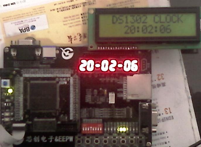
运行结果,可以发现LCD内容要比LED数码管内容显示时间要慢大约0.5秒,可能是因为LCD的是慢扫描器件所致。
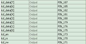
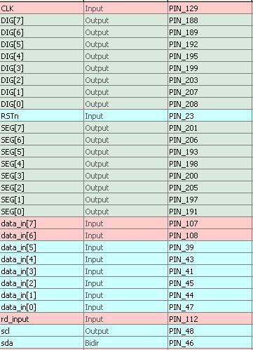
LCD1602 I/O分配图
点击下载DS1302.rar
44楼
进程18、I2C
实验中设置接口板的DIP开关作为I2C“写”数据输入口,按键1执行“读”操作,按键8执行“写”操作。数码LED的高2位显示“读”的十六进制值,最低2位显示“写”的数据十六进制值。运行时拨动DIP开关到欲写入的值,按一下按键8写入,然后按一下按键1读出。
input CLK,RSTn;
output scl;
inout sda;
input[7:0] data_in;//DIP开关
input wr_input;
input rd_input;
reg scl;
reg sda_buf;
reg link;
reg phase0,phase1,phase2,phase3;
//EEPROM操作部分代码
parameter
start=4'b0000, //开始
step1=4'b0001, //第1位
step2=4'b0010,//第2位
step3=4'b0011, //第3位
step4=4'b0100, //第4位
step5=4'b0101, //第5位
step6=4'b0110, //第6位
step7=4'b0111, //第7位
step8=4'b1000, //第8位
ack=4'b1001, //确认位
stop=4'b1010; //结束位
inout sda;//I2C数据线
assign sda=(link)? sda_buf:1'bz;
//读EEPROM
begin
if(phase0)
scl<=1;
else if(phase2)
scl<=0;
case(i2c_state)
ini: begin
case(inner_state)
start: begin
if(phase1) begin
link<=1;
sda_buf<=0;
end
if(phase3&&link) begin
inner_state<=step1;
sda_buf<=1;
link<=1;
end
end
step1:
if(phase3) begin
sda_buf<=0;
link<=1;
inner_state<=step2;
end
step2:
if(phase3) begin
sda_buf<=1;
link<=1;
inner_state<=step3;
end
step3:
if(phase3) begin
sda_buf<=0;
link<=1;
inner_state<=step4;
end
step4:
if(phase3) begin
sda_buf<=0;
link<=1;
inner_state<=step5;
end
step5:
if(phase3) begin
sda_buf<=0;
link<=1;
inner_state<=step6;
end
step6:
if(phase3) begin
sda_buf<=0;
link<=1;
inner_state<=step7;
end
step7:
if(phase3) begin
sda_buf<=0;
link<=1;
inner_state<=step8;
end
step8:
if(phase3) begin
link<=0;
inner_state<=ack;
end
ack: begin
if(phase0)
sda_buf<=sda;
if(phase1) begin
if(sda_buf==1)
main_state<=2'b00;
end
if(phase3) begin
link<=1;
sda_buf<=addr[7];
inner_state<=step1;
i2c_state<=sendaddr;
end
end
endcase
end
//数码LED部分代码
output[7:0] DIG;//数码管使能
output[7:0] SEG;//数码管段数据
reg[7:0] SEG;
reg[7:0] DIG;
reg[15:0] cnt_scan;
reg[5:0] SEG_buf;
always @(cnt_scan)
begin
case(cnt_scan[15:13])
3'b000 : DIG = 8'b1111_1110;
3'b001 : DIG = 8'b1111_1101;
3'b010 : DIG = 8'b1111_1011;
3'b011 : DIG = 8'b1111_0111;
3'b100 : DIG = 8'b1110_1111;
3'b101 : DIG = 8'b1101_1111;
3'b110 : DIG = 8'b1011_1111;
3'b111 : DIG = 8'b0111_1111;
default :DIG = 8'b1111_1110;
endcase
end
always@(DIG)
begin
case(DIG)
8'b11111101: SEG_buf=writeData_reg[7:4];
8'b11111110: SEG_buf=writeData_reg[3:0];
8'b10111111: SEG_buf=readData_reg[3:0];
8'b01111111: SEG_buf=readData_reg[7:4];
default: SEG_buf=9'h10;
endcase
end
always@(SEG_buf)
begin
case(SEG_buf)
4'b0000:SEG=8'b1100_0000;
4'b0001:SEG=8'b1111_1001;
4'b0010:SEG=8'b1010_0100;
4'b0011:SEG= 8'b1011_0000;
4'b0100:SEG=8'b1001_1001;
4'b0101:SEG=8'b1001_0010;
4'b0110:SEG=8'b1000_0010;
4'b0111:SEG=8'b 1111_1000;
4'b1000:SEG=8'b1000_0000;
4'b1001:SEG=8'b1001_0000;
4'b1010:SEG=8'b1000_1000;
4'b1011:SEG=8'b1000_0011;
4'b1100:SEG=8'b1100_0110;
4'b1101:SEG=8'b1001_0001;
4'b1110:SEG= 8'b1000_0110;
4'b1111:SEG=8'b1000_1110;
default:SEG=8'hff;
endcase
end
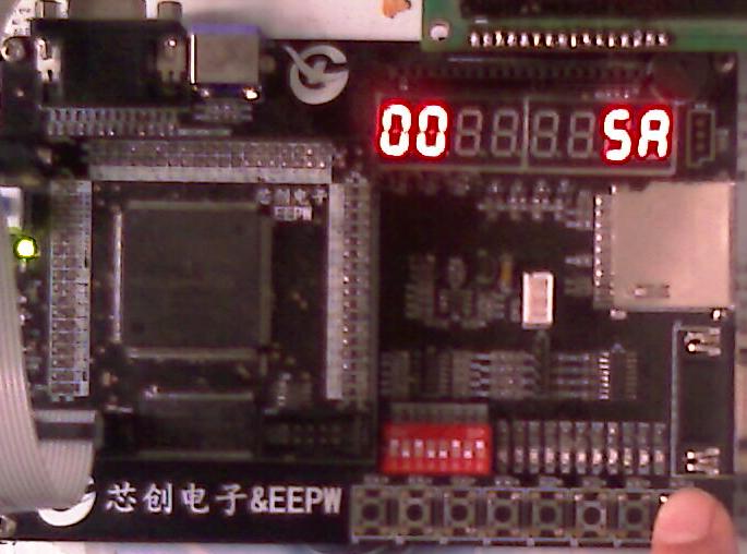
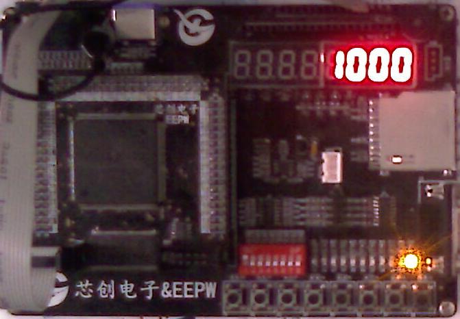
写入5AH
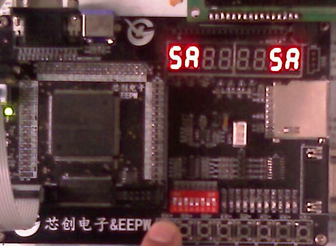
读出写入的数据
I/O分配表
点击下载i2c.rar
45楼
进程19、数字频率计
门控信号发生器从50M时钟分频出门控信号gate_out,在gate_out的时间间隔内对信号频率的变化次数FQ_in进行计数,则信号频率f=FQ_in/gate_out.这里设定门控信号时间为1秒,在gate_out的上升沿开始对FQ_in计数,在gate_out的下降沿将7位的计数值锁存,然后送LED数码管显示。LED数码显示已经考虑到高位无用零消隐的功能。接口板上LCD1602的RS引脚用来作为外部待测信号输入端。要求输入的信号是TTL电平方波。黄色LED用来监视gate_out状态。
//部分代码
module frequ(
CLK,
RESET,
FQ_in,
sm_seg,
sm_bit,
YELLOW
);
input CLK;
input RESET;
input FQ_in;
output YELLOW;
//门控信号
reg gate_out;
reg gate;
always @(posedge gate or negedge RESET)
begin
if(!RESET )
gate_out <=0;
else
gate_out<=~gate_out;
end
//---------------------------------
always @(posedge clk_1khz or negedge RESET)
begin
if(!RESET)
gate<=0;
else
gate<=clk_1hz;
end
assign YELLOW=gate_out;
//----------------------------------------
//频率计数
reg [3:0]FqCount0,FqCount1,FqCount2,FqCount3,FqCount4,FqCount5,FqCount6;
reg [3:0] Fqout0,Fqout1,Fqout2,Fqout3,Fqout4,Fqout5,Fqout6;
reg[2:0]counter6;
always @(posedge FQ_in or negedge RESET)
begin
if(!RESET)
begin
FqCount0<=4'b0000;FqCount1<=4'b0000;FqCount2<=4'b0000;FqCount3<=4'b0000;
FqCount4<=4'b0000;FqCount5<=4'b0000;FqCount6<=4'b0000;
Fqout0<=4'b0000;Fqout1<=4'b0000;Fqout2<=4'b0000;Fqout3<=4'b0000;
Fqout4<=4'b0000;Fqout5<=4'b0000;Fqout6<=3'b000;
end else begin if(gate_out==1) begin
counter6<=0;
if((FqCount5==4'b1001)&&(FqCount4==4'b1001)&&(FqCount3==4'b1001)
&&(FqCount2==4'b1001)&&(FqCount1==4'b1001)&&(FqCount0==4'b1001)) begin
FqCount0<=4'b0000;FqCount1<=4'b0000;FqCount2<=4'b0000;FqCount3<=4'b0000;
FqCount4<=4'b0000;FqCount5<=4'b0000;FqCount6<=FqCount6+4'b0001; end else begin
if((FqCount4==4'b1001)&&(FqCount3==4'b1001)&&(FqCount2==4'b1001)
&&(FqCount1==4'b1001)&&(FqCount0==4'b1001)) begin
FqCount0<=4'b0000;FqCount1<=4'b0000;FqCount2<=4'b0000;FqCount3<=4'b0000;
FqCount4<=4'b0000;FqCount5<=4'b0001+FqCount5;FqCount6<=FqCount6;
end else begin if((FqCount3==4'b1001)&&(FqCount2==4'b1001)&&(FqCount1==4'b1001)
&&(FqCount0==4'b1001)) begin
FqCount0<=4'b0000;FqCount1<=4'b0000;FqCount2<=4'b0000;FqCount3<=4'b0000;
FqCount4<=4'b0001+FqCount4;FqCount5<=FqCount5;FqCount6<=FqCount6;
end else begin
if((FqCount2==4'b1001)&&(FqCount1==4'b1001)&&(FqCount0==4'b1001))begin
FqCount0<=4'b0000;FqCount1<=4'b0000;FqCount2<=4'b0000;FqCount3<=4'b0001+FqCount3;
FqCount4<=FqCount4;FqCount5<=FqCount5;FqCount6<=FqCount6;
end else begin if((FqCount1==4'b1001)&&(FqCount0==4'b1001))begin
FqCount0<=4'b0000;FqCount1<=4'b0000;FqCount2<=4'b0001+FqCount2;FqCount3<=FqCount3;
FqCount4<=FqCount4;FqCount5<=FqCount5;FqCount6<=FqCount6;
end else begin if(FqCount0==4'b1001) begin
FqCount0<=4'b0000;FqCount1<=4'b0001+FqCount1;FqCount2<=FqCount2;FqCount3<=FqCount3;
FqCount4<=FqCount4;FqCount5<=FqCount5;FqCount6<=FqCount6;
end else begin
FqCount0<=4'b0001+FqCount0;FqCount1<=FqCount1;FqCount2<=FqCount2;FqCount3<=FqCount3;
FqCount4<=FqCount4;FqCount5<=FqCount5;FqCount6<=FqCount6;
end end end end end end end else begin
if(counter6==2'b01) begin
FqCount0<=4'b0000;FqCount1<=4'b0000;FqCount2<=4'b0000;FqCount3<=4'b0000;
FqCount4<=4'b0000;FqCount5<=4'b0000;FqCount6<=4'b0000;
end else begin
counter6<=counter6+1;Fqout0<=FqCount0;Fqout1<=FqCount1;Fqout2<=FqCount2;Fqout3<=FqCount3;
Fqout4<=FqCount4;Fqout5<=FqCount5;Fqout6<=FqCount6;
end end end end
//---------------------------------------------------
//显示
output [7:0] sm_seg;
output [7:0] sm_bit ;
reg [7:0] sm_seg;
reg [7:0] sm_bit ;
reg[7:0] dataout_buf;
always @(counter4)
begin
case(counter4[12:10])
3'b000 : sm_bit = 8'b1111_1110;
3'b001 : sm_bit = 8'b1111_1101;
3'b010 : sm_bit = 8'b1111_1011;
3'b011 : sm_bit = 8'b1111_0111;
3'b100 : sm_bit = 8'b1110_1111;
3'b101 : sm_bit = 8'b1101_1111;
3'b110 : sm_bit = 8'b1011_1111;
3'b111 : sm_bit = 8'b1111_1111;
default : sm_bit = 8'b1111_1110;
endcase
end
//-----------------------------
always@(sm_bit)
begin
case(sm_bit)
8'b1111_1110: dataout_buf=Fq_data0;
8'b1111_1101: begin
if(Fq_data6==0 && Fq_data5==0 && Fq_data4==0 && Fq_data3==0 && Fq_data2==0 && Fq_data1==0)
dataout_buf=10;
else
dataout_buf=Fq_data1;
end
8'b1111_1011: begin
if(Fq_data6==0 && Fq_data5==0 && Fq_data4==0 && Fq_data3==0 && Fq_data2==0 )
dataout_buf=10;
else
dataout_buf=Fq_data2;
end
8'b1111_0111: begin
if(Fq_data6==0 && Fq_data5==0 && Fq_data4==0 &&Fq_data3==0)
dataout_buf=10;
else
dataout_buf=Fq_data3;
end
8'b1110_1111: begin
if(Fq_data6==0 && Fq_data5==0 && Fq_data4==0)
dataout_buf=10;
else
dataout_buf=Fq_data4;
end
8'b1101_1111: begin
if(Fq_data6==0 &&Fq_data5==0)
dataout_buf=10;
else
dataout_buf=Fq_data5;
end
8'b1011_1111: begin
if(Fq_data6==0)
dataout_buf = 10;
else
dataout_buf=Fq_data6;
end
default:
dataout_buf=10;
endcase
end
//-------------------
always@(dataout_buf)
begin
case(dataout_buf)
4'h0 : sm_seg = 8'hc0;
4'h1 : sm_seg = 8'hf9;
4'h2 : sm_seg = 8'ha4;
4'h3 : sm_seg = 8'hb0;
4'h4 : sm_seg = 8'h99;
4'h5 : sm_seg = 8'h92;
4'h6 : sm_seg = 8'h82;
4'h7 : sm_seg = 8'hf8;
4'h8 : sm_seg = 8'h80;
4'h9 : sm_seg = 8'h90;
4'ha : sm_seg = 8'hff;
endcase
end
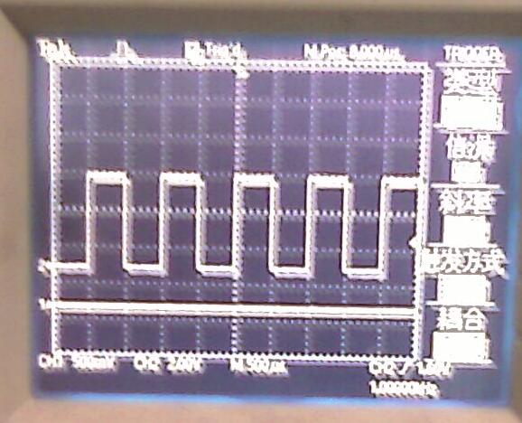
从示波器标准信号输入信号频率为1000HZ的方波
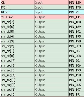
I/O分配图
点击下载frequ.rar
回复
| 有奖活动 | |
|---|---|
| 硬核工程师专属补给计划——填盲盒 | |
| “我踩过的那些坑”主题活动——第002期 | |
| 【EEPW电子工程师创研计划】技术变现通道已开启~ | |
| 发原创文章 【每月瓜分千元赏金 凭实力攒钱买好礼~】 | |
| 【EEPW在线】E起听工程师的声音! | |
| 高校联络员开始招募啦!有惊喜!! | |
| 【工程师专属福利】每天30秒,积分轻松拿!EEPW宠粉打卡计划启动! | |
| 送您一块开发板,2025年“我要开发板活动”又开始了! | |
 我要赚赏金打赏帖 我要赚赏金打赏帖 |
|
|---|---|
| Chaos-nano操作系统在手持式VOC检测设备上的应用被打赏¥37元 | |
| 【分享开发笔记,赚取电动螺丝刀】关于在导入第三方库lib时,wchart类型冲突的原因及解决方案被打赏¥30元 | |
| 在FireBeetle2ESP32-C5上实现温湿度检测和显示被打赏¥20元 | |
| 在FireBeetle2ESP32-C5上实现光照强度检测及显示被打赏¥21元 | |
| 以FireBeetle2ESP32-C5实现数据识读播报被打赏¥19元 | |
| 【STM32F103ZET6】14:实测STM32F1的串口输出任务的挂起与恢复功能被打赏¥27元 | |
| Chaos-nano在压力容器监控系统中的项目应用被打赏¥23元 | |
| 基于FireBeetle2ESP32-C5的WS2812B彩色灯带控制被打赏¥21元 | |
| SWM221CBT7显示开发板驱动TFT显示屏被打赏¥19元 | |
| SWM221CBT7显示开发板驱动OLED屏显示被打赏¥19元 | |
 STM32
STM32 MCU
MCU 通讯及无线技术
 物联网技术
物联网技术 电子DIY
电子DIY 板卡试用
板卡试用 基础知识
基础知识 软件与操作系统
 我爱生活
我爱生活 小e食堂
小e食堂

