
计算延时线的最高工作频率
摘要:延迟线在应用中要求一个(纳秒),或者增量时间更正为系统正常工作所需的几纳秒信号延迟。 This application note discusses the maximum frequency that the input signal could have, and the maximum delay that can be obtained. 本应用指南讨论了最高频率的输入信号可以,最大的延迟可以得到。
A similar version of this article was published on February 24, 2009 on the Industrial Control DesignLine website.这个类似文章发表在2009年2月24日在工业控制DesignLine网站。
Calculating Maximum Input Frequency计算最大输入频率
When calculating the maximum input frequency, the critical parameter to consider is the minimum pulse width of the input signal.当计算的最大输入频率,最重要的参数要考虑的是输入信号的最小脉冲宽度。 For periodic signals with a 50% duty cycle, the minimum pulse width would be half the period of the signal.对于具有50%的占空比,最小脉宽周期信号将一半的一段期间的信号。 This value, in turn, determines the maximum possible delay.此值,从而决定了最大可能延误。 Sometimes the input is periodic with a low frequency, but with a duty cycle of less than 50%.有时,是周期性的输入与低频,但低于50%的占空比。 In this case, the width of the minimum duration between transitions (t WI ) on the input determines the minimum pulse width ( Figure 1 ).在这种情况下,之间的转换(吨威斯康星州 )最短的输入宽度确定最小脉宽( 图1)。 In a number of devices, the minimum-input pulse width possible is specified as 100% of the maximum output delay desired (if not explicitly specified).在许多设备,最小输入脉冲宽度可能被指定为100%,最高产量所需的延迟(如果没有明确规定)。 The maximum output delay for these devices is, therefore (conversely), the same as the minimum-input pulse width.这些器件的最大输出延迟,因此(反过来),在相同的最低输入脉冲宽度。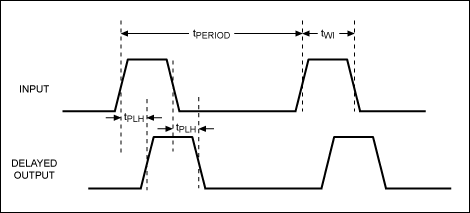
Figure 1. 图1。 Illustration shows how the minimum duration between transitions (t WI ) of the input signal determines the maximum possible delay. 图显示与输入信号的转换(吨威斯康星州 )最低期限确定最大的延误。
Maximum Input Frequency for Programmable Delay Lines最大输入频率为可编程延时线
The specifications to consider for programmable delay lines are found in the product data sheet:这些规范考虑可编程延时线是在产品数据表中:- Zero-step delay (t PHL_MIN or t PLH_MIN )零延迟步(吨PHL_MIN或t PLH_MIN)
- Minimum-input pulse width (t WI_MIN )最小输入脉冲宽度(吨WI_MIN)
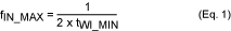
Table 1 gives some examples of the maximum allowable frequency for various devices. 表1给出了最高频率的各种设备允许的一些例子。
Table 1. 表1。 Maximum Input Frequencies for Programmable Delay Lines 最大输入频率为可编程延时线
| Part Number零件编号 | Description描述 | Minimum or Zero-Step Delay, t PHL_MIN or t PLH_MIN (ns)最低或零延迟步,吨PHL_MIN或吨PLH_MIN(NS)的 | Maximum Zero-Step Delay (ns)最大零延迟步(NS)的 | Minimum Pulse Width t WI_MIN (ns)最小脉宽吨WI_MIN(NS)的 | Maximum Input Frequency (MHz)最大输入频率(MHz) | |
| DS1020-100 DS1020 - 100 | 8-bit silicon delay line 8位硅延迟线 | 10 ± 2 10 ± 2 | 12 12 | 100% of output delay 100%的输出延迟 | 12 12 | 41.67 41.67 |
| DS1020-25 DS1020 - 25 | 8-bit silicon delay line 8位硅延迟线 | 10 ± 2 10 ± 2 | 12 12 | 100% of output delay 100%的输出延迟 | 12 12 | 41.67 41.67 |
| DS1021-25 DS1021 - 25 | 8-bit silicon delay line 8位硅延迟线 | 10 ± 2 10 ± 2 | 12 12 | 100% of output delay 100%的输出延迟 | 12 12 | 41.67 41.67 |
| DS1023-25 DS1023 - 25 | 8-bit timing element 8位定时元件 | 16.5 16.5 | 22 22 | 20 20 | 20 20 | 25 25 |
| DS1023-500 DS1023 - 500 | 8-bit timing element 8位定时元件 | 16.5 16.5 | 22 22 | 50 50 | 50 50 | 10 10 |
| DS1045-3 DS1045 - 3 | 4-bit dual delay line 4位双延迟线 | 9 ± 1 9 ± 1 | 10 10 | 100% of output delay 100%的输出延迟 | 10 10 | 50 50 |
Maximum Input Frequency for Nonprogrammable Delay Lines最大输入频率为不可编程延时线
For nonprogrammable delay lines, the specifications to consider are also found in the product data sheet:对于不可编程延时线,规格也考虑在产品数据表中:- Delay at maximum tap position在最大延迟抽头位置
- Minimum-input pulse width (t WI_MIN )最小输入脉冲宽度(吨WI_MIN)
Table 2 shows some examples of the maximum allowable frequency for various nonprogrammable devices. 表2显示了不同的最高允许的频率不可编程器件的一些例子。
Table 2. 表2。 Maximum Input Frequencies for Nonprogrammable Delay Lines 最大输入频率为不可编程延时线
| Part Number零件编号 | Description描述 | Delay at Maximum Tap Position在最大延迟抽头位置 | Maximum Delay at Max Tap Position最大的最大延迟抽头位置 | Minimum Pulse Width, t WI_MIN (ns)最小脉宽,吨WI_MIN(NS)的 | Maximum Input Frequency (MHz)最大输入频率(MHz) | |
| DS1110LE-200 DS1110LE - 200 | 3V, 10-tap silicon delay line 3V的,10抽头硅延迟线 | 200 200 | 200 200 | 10% of tap 10 delay 10%的自来水10延误 | 20 20 | 25 25 |
| DS1110LE-500 DS1110LE - 500 | 3V, 10-tap silicon delay line 3V的,10抽头硅延迟线 | 500 500 | 500 500 | 10% of tap 10 delay 10%的自来水10延误 | 50 50 | 10 10 |
| DS1135-6 DS1135 - 6 | 3-in-1 high-speed silicon delay line 3合1高速硅延迟线 | 6 ± 1 6 ± 1 | 7 7 | 100% of tap delay 100%的节拍延迟 | 7 7 | 71.43 71.43 |
| DS1135-30 DS1135 - 30 | 3-in-1 high-speed silicon delay line 3合1高速硅延迟线 | 30 ± 1.5 30 ± 1.5 | 31.5 31.5 | 100% of tap delay 100%的节拍延迟 | 31.5 31.5 | 15.87 15.87 |
Calculating Maximum Frequency for an Application计算应用程序最大频率
For programmable delay lines : if a delay higher than the minimum delay is required, then the minimum pulse width allowable is calculated as:对于可编程延时线 :如果拖延高于最低延迟要求较高,则允许的最小脉冲宽度计算公式为:Minimum Pulse Width = Maximum Step-Zero Delay + Programmed Delay.最小脉冲宽度=最大步零延迟+程序延迟。
The maximum allowable frequency can then be calculated using Equation 1.最大允许的频率可以被计算公式1。
Example for Programmable Delay Lines 示例可编程延时线
- Device used: DS1020-100设备使用:DS1020 - 100
Desired delay: 25ns期望延迟时间:25ns
Minimum pulse width = 25ns + 12ns = 37ns最小脉冲宽度= 25ns的+ 12ns = 37ns
Maximum allowable input frequency = 1/(2 × 37ns) = 18.52MHz最大允许输入频率= 1 /(2 × 37ns)= 18.52MHz - Device used: DS1023-500设备使用:DS1023 - 500
Desired delay: 60ns期望延迟:60纳秒
Minimum pulse width = 22ns + 60ns = 82ns最小脉冲宽度= 22ns + 60纳秒= 82ns
Maximum allowable input frequency = 1/(2 × 82ns) = 6.1MHz最大允许输入频率= 1 /(2 × 82ns)= 6.1MHz
 我要赚赏金
我要赚赏金 STM32
STM32 MCU
MCU 通讯及无线技术
 物联网技术
物联网技术 电子DIY
电子DIY 板卡试用
板卡试用 基础知识
基础知识 软件与操作系统
 我爱生活
我爱生活 小e食堂
小e食堂

