
RTC实时时钟的实验本来是非常简单的,但是这次版主花掉了不少的时间,而且是在认真的阅读了官方的数据手册才debug出来问题的所在。在一定程度上浪费了时间。
版主也本着分享与节省各位网友时间的前提下,将本次“失败”的编程经验帖出来。
本次实验的目的就是实现GD32F130的RTC外设;
实验的内容是利用GD32F130C-Start开发板上自带的32.768KHz的晶振来产生实时时钟所需要外置低速时钟源。
由于版主之前并没有接触过芯片的实时时钟配置(版主之前使用DS1302),因此,版主从网上下载了一些demo示例来移植的。虽然版主没有编写过RTC的程序,但是GD32简单的应用感觉工作也不会太难。
可是,问题恰恰就发生在网上下载的demo示例里。
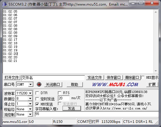
版主的想法是,将RTC时钟初始化为1点2分3秒,但是移植后实验结果就是失败。无论如何设置时间均以失败告终。通过查询库函数文件,发现仅通过RTC_SetTime函数即可,但是结果却是不同。
开始怀疑是芯片的不同造成的,查询数据手册后发现,并无特殊配置要求,这里再将返回源代码进行debug发现,demo示例里居然将时间设置函数优先于RTC实时初始化之前了。
RTC实时时钟能没有开启,又如何能设置时间啊~~
轻信网上的demo示例损坏2天的时间,怒!!!
版主将调试成本的源代码分享如下:
/**
  * @brief  RTCconfig
  * @param
  * @retval
  * @date   2015-04-01
  * @note
  */

void RTCconfig(void)
{
  ErrorStatus RTCstatus;
  RTC_InitTypeDef  RTC_InitStructure;
  RTC_TimeTypeDef  RTC_TimeStruct;
  uint8_t TimeOut = 0xFF;

  /* Enable the PWR clock */
  RCC_APB1PeriphClockCmd(RCC_APB1Periph_PWR, ENABLE);

  /* Allow access to RTC */
  PWR_BackupAccessCmd(ENABLE);

  /* Reset RTC Domain */
  RCC_BackupResetCmd(ENABLE);
  RCC_BackupResetCmd(DISABLE);

  /* Enable the LSE OSC */
  RCC_LSEConfig(RCC_LSE_ON);

  /* Wait till LSE is ready */
  while(RCC_GetFlagStatus(RCC_FLAG_LSERDY) == RESET)
  {}

  /* Select the RTC Clock Source */
  RCC_RTCCLKConfig(RCC_RTCCLKSource_LSE);

  RTC_WriteProtectionCmd(DISABLE);

  /* Configure the RTC data register and RTC prescaler */
  /* ck_spre(1Hz) = RTCCLK(LSI) /(AsynchPrediv + 1)*(SynchPrediv + 1)*/
  RTC_InitStructure.RTC_AsynchPrediv = 0x7F;
  RTC_InitStructure.RTC_SynchPrediv  = 0xFF;
  RTC_InitStructure.RTC_HourFormat   = RTC_HourFormat_24;
  RTC_Init(&RTC_InitStructure);

  RCC_RTCCLKCmd(ENABLE);
  RTC_WaitForSynchro();

  /* Set the time to 00h 00mn 00s AM */
  RTC_TimeStruct.RTC_H12     = RTC_H12_AM;
  RTC_TimeStruct.RTC_Hours   = 0x01;
  RTC_TimeStruct.RTC_Minutes = 0x02;
  RTC_TimeStruct.RTC_Seconds = 0x03;
  do
  {
    RTCstatus = RTC_SetTime(RTC_Format_BCD, &RTC_TimeStruct);
    TimeOut--;
  }while((RTCstatus == ERROR) & (TimeOut > 0));
  if(RTCstatus == ERROR)
  {
    while(1)
    {
      ;
    }
  }

//  RCC_RTCCLKCmd(ENABLE);  /*!< 网上示例在此初始化 */
//  RTC_WaitForSynchro();
}


/**
  * @brief  key check
  * @param
  * @retval
  * @date   2015-03-28
  * @note
  */

void KeyCheck(void)
{
  bool KeyStatus;
  KeyStatus = KeyScan(0);

  switch(gKeyStatus)
  {
    case 0:  /*!< 空闲状态 */
    {
      if(KeyStatus == true)
      {
        gKeyStatus = 1;
      }
      else
      {
        gKeyStatus = 0;
        LedOff(0);
        gSendCmdStatus = 0;
      }
      break;
    }
    case 1:  /*!< 消抖状态 */
    {
      if(KeyStatus == true)
      {
        gKeyCnt = 5;
        gKeyStatus = 2;
      }
      else
      {
        gKeyCnt = 0;
        gKeyStatus = 0;
      }
      break;
    }
    case 2:  /*!< 按下状态 */
    {
      if(KeyStatus == true)
      {
        if(gKeyCnt == 0)
        {
          //按键按下执行内容
          LedOn(0);
          gSendCmdStatus |= 0x0F;
        }
        else
        {
          gKeyStatus = 2;
        }
      }
      else
      {
        gKeyCnt = 0;
        gKeyStatus = 0;
      }
      break;
    }
    case 3:  /*!< 确认按下 */
    {
      LedOn(0);
      break;
    }
    default: gKeyStatus = 0;
  }

}

/**
  * @brief  uart_int
  * @param
  * @retval
  * @date   2015-03-29
  * @note   发送使用DMA方式,接收使用中断
  */

void UartConfig(uint32_t band)
{
  USART_InitTypeDef USART_InitStructure;
  GPIO_InitTypeDef  GPIO_InitStructure;
  NVIC_InitTypeDef NVIC_InitStructure;
  DMA_InitTypeDef  DMA_InitStructure;

  RCC_AHBPeriphClockCmd(RCC_AHBPeriph_GPIOA, ENABLE);
  RCC_APB2PeriphClockCmd (RCC_APB2Periph_USART1, ENABLE);
  RCC_AHBPeriphClockCmd(RCC_AHBPeriph_DMA1, ENABLE);


  /* Connect pin to Periph */
  GPIO_PinAFConfig(GPIOA, GPIO_PinSource9, GPIO_AF_1);
  GPIO_PinAFConfig(GPIOA, GPIO_PinSource10, GPIO_AF_1);

  /* Configure pins as AF pushpull */
  GPIO_InitStructure.GPIO_Pin     = GPIO_Pin_9 | GPIO_Pin_10;
  GPIO_InitStructure.GPIO_Mode    = GPIO_Mode_AF;
  GPIO_InitStructure.GPIO_Speed   = GPIO_Speed_50MHz;
  GPIO_InitStructure.GPIO_OType   = GPIO_OType_PP;
  GPIO_InitStructure.GPIO_PuPd    = GPIO_PuPd_NOPULL;

  GPIO_Init(GPIOA, &GPIO_InitStructure);

  USART_InitStructure.USART_BaudRate = band;
  USART_InitStructure.USART_WordLength = USART_WordLength_8b;
  USART_InitStructure.USART_StopBits = USART_StopBits_1;
  USART_InitStructure.USART_Parity = USART_Parity_No;
  USART_InitStructure.USART_HardwareFlowControl = USART_HardwareFlowControl_None;
  USART_InitStructure.USART_Mode = USART_Mode_Rx | USART_Mode_Tx;

  USART_Init(USART1, &USART_InitStructure);

  /* NVIC configuration */
  /* Enable the USARTx Interrupt */
  NVIC_InitStructure.NVIC_IRQChannel = USART1_IRQn;
  NVIC_InitStructure.NVIC_IRQChannelPriority = 0;
  NVIC_InitStructure.NVIC_IRQChannelCmd = ENABLE;
  NVIC_Init(&NVIC_InitStructure);

  USART_ITConfig(USART1, USART_IT_RXNE, ENABLE);

  DMA_InitStructure.DMA_PeripheralDataSize = DMA_PeripheralDataSize_Byte;
  DMA_InitStructure.DMA_MemoryDataSize = DMA_MemoryDataSize_Byte;
  DMA_InitStructure.DMA_PeripheralInc = DMA_PeripheralInc_Disable;
  DMA_InitStructure.DMA_MemoryInc = DMA_MemoryInc_Enable;
  DMA_InitStructure.DMA_Mode = DMA_Mode_Normal;
  DMA_InitStructure.DMA_M2M = DMA_M2M_Disable;

  DMA_DeInit(DMA1_Channel2);
  DMA_InitStructure.DMA_PeripheralBaseAddr = USART1_TDR_ADDRESS;
  DMA_InitStructure.DMA_BufferSize = (uint16_t)256;
  DMA_InitStructure.DMA_MemoryBaseAddr = (uint32_t)(&gSendBuf[0]);
  DMA_InitStructure.DMA_DIR = DMA_DIR_PeripheralDST;
  DMA_InitStructure.DMA_Priority = DMA_Priority_VeryHigh;

  DMA_Init(DMA1_Channel2, &DMA_InitStructure);

  USART_DMACmd(USART1, USART_DMAReq_Tx, ENABLE);
  USART_Cmd(USART1, ENABLE);
}

void main(void)
{
  uint16_t i;
  RTC_TimeTypeDef  RTC_TimeStruct;

  int8_t Str[] = "hello EEPW\r\n";
  gKeyStatus = 0;
  bspInit();
  gCntLed[0] = 500;
  gCntLed[1] = 500;
  TxIndex = 0;
  gSendCnt = 12;
  for(i = 0; i < gSendCnt; i++)
  {
    gSendBuf[i] = Str[i];
  }
  UartConfig(115200);
  if (SysTick_Config(48000)) //参数为系统时钟的向上溢出值,此配置为48000,即1ms中断一次
  {
    /* Capture error */
    while (1);
  }

  RTCconfig();

  while(1)
  {
    if(gCntLed[1] == 0)
    {
      LedToggle(1);
      gCntLed[1] = gRcvBuf[0] * 4;
    }
    KeyCheck();

    if(gSendCmdStatus > 0)
    {
      if(gSendCmdStatus < 0x10)
      {
        RTC_GetTime(RTC_Format_BCD, &RTC_TimeStruct);
        gSendBuf[0] = RTC_TimeStruct.RTC_Hours / 10 + '0';
        gSendBuf[1] = RTC_TimeStruct.RTC_Hours % 10 + '0';
        gSendBuf[2] = ':';
        gSendBuf[3] = RTC_TimeStruct.RTC_Minutes / 10 + '0';
        gSendBuf[4] = RTC_TimeStruct.RTC_Minutes % 10 + '0';
        gSendBuf[5] = ':';
        gSendBuf[6] = RTC_TimeStruct.RTC_Seconds / 10 + '0';
        gSendBuf[7] = RTC_TimeStruct.RTC_Seconds % 10 + '0';
        gSendBuf[8] = '\r';
        gSendBuf[9] = '\n';

        DMA_Cmd(DMA1_Channel2, DISABLE);
        DMA_SetCurrDataCounter(DMA1_Channel2, 10);
        DMA_Cmd(DMA1_Channel2, ENABLE);
        gSendCmdStatus |= 0xF0;
      }
    }

  }
}

/**
  * @brief  SysTick_Handler的中断入口函数
  * @param
  * @retval
  * @date   2014-11-23
  * @note
  */

void SysTick_Handler(void)
{
  if(gCntLed[0] > 0)
  {
    gCntLed[0]--;
  }
  else
  {
    gCntLed[0] = 0;
  }

  if(gCntLed[1] > 0)
  {
    gCntLed[1]--;
  }
  else
  {
    gCntLed[1] = 0;
  }

  if(gKeyCnt > 0)
  {
    gKeyCnt--;
  }
  else
  {
    gKeyCnt = 0;
  }
}

/**
  * @brief  USART1_Handler的中断入口函数
  * @param
  * @retval
  * @date   2015-03-29
  * @note
  */

void USART1_IRQHandler(void)
{
  if (USART_GetITStatus(USART1, USART_IT_RXNE) == SET)
  {
    gRcvBuf[0] = USART_ReceiveData(USART1);
  }
}
工程如下:
 我要赚赏金
我要赚赏金 STM32
STM32 MCU
MCU 通讯及无线技术
 物联网技术
物联网技术 电子DIY
电子DIY 板卡试用
板卡试用 基础知识
基础知识 软件与操作系统
 我爱生活
我爱生活 小e食堂
小e食堂

