这些小活动你都参加了吗?快来围观一下吧!>>
电子产品世界 » 论坛首页 » 嵌入式开发 » STM32 » 余弦的STM32 L053开发板试用记录贴【更新中】

共18条 1/2 1 2 跳转至

余弦的STM32 L053开发板试用记录贴【更新中】

工程师
2016-01-21 13:49:33     打赏

感谢萌主给了我这个开发板试用的机会。

因为时间原因,板子收到吃了一段时间灰,没有及时写测评,在此感到对不起盟主,不知道有没有被拉黑


下面进入正题:。。。。。。。。。。。。。。。。


菜鸟
2016-01-21 15:35:17     打赏
2楼

助工
2016-01-21 17:05:04     打赏
3楼
正题呢。。。

工程师
2016-01-21 22:03:52     打赏
4楼
你已经进入黑名单了

高工
2016-01-22 00:28:51     打赏
5楼

都申请快2个月了........................


工程师
2016-02-20 10:37:53     打赏
6楼
来了来了

工程师
2016-02-20 10:38:16     打赏
7楼
最近有空了,走起。。。。。。。。。。。。。。。。。。。。。

工程师
2016-02-20 10:48:47     打赏
8楼

开发方式

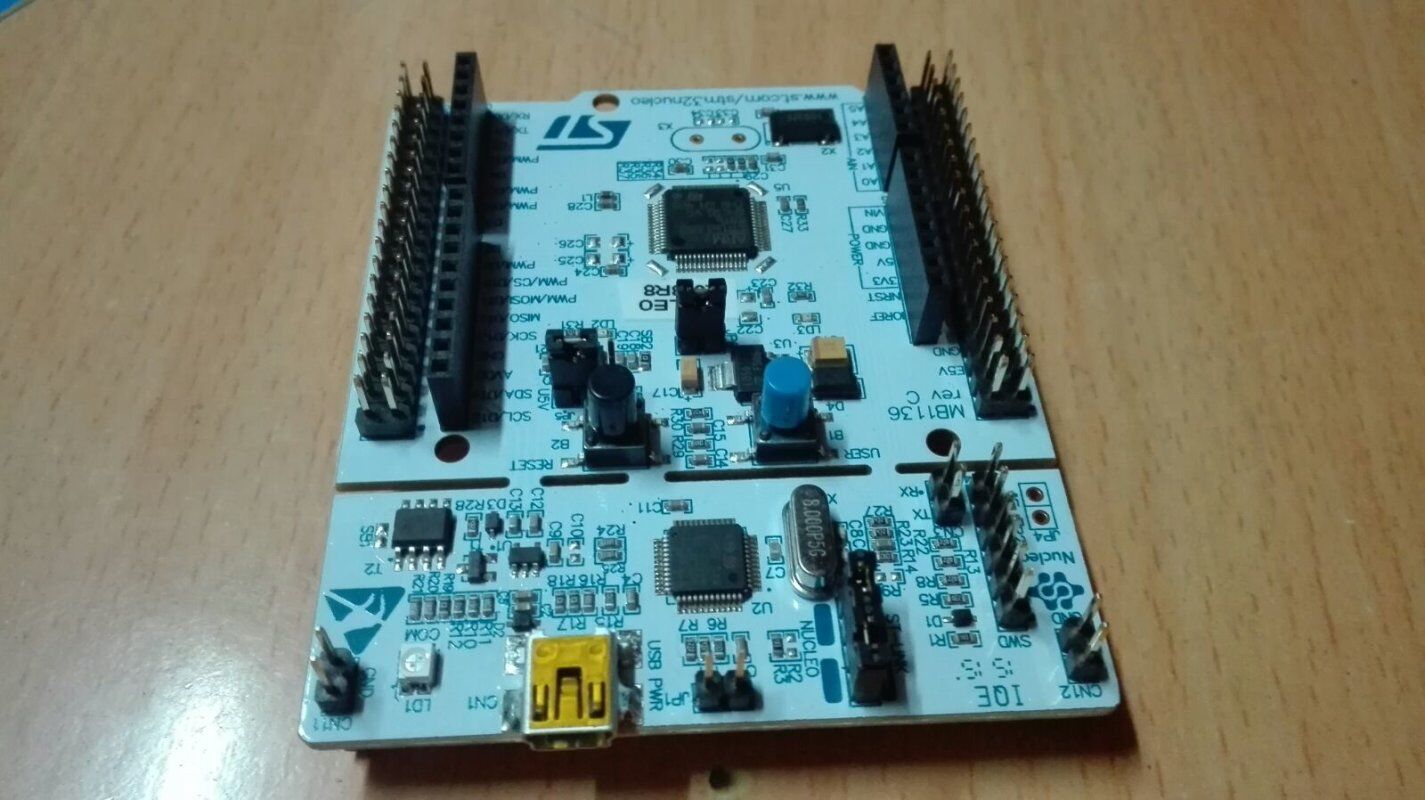
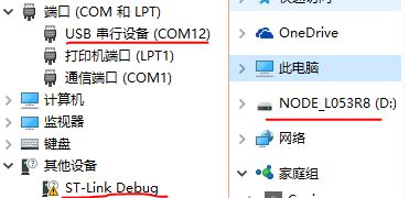
nucleo(下称核板)开发板果然与众不同,通过usb链接PC后,出现三个设备,从上到下分别是串口、储存设备、link Debug设备,最后一个设备需要驱动才能使用。

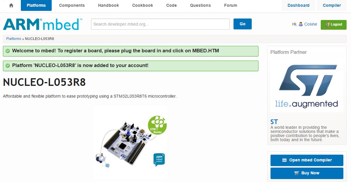
那么集成开发环境呢,找了一圈才知道,原来就是磁盘里那个网页文件跳转后的STM Mbed平台。

打开网页能自动进入平台,注册新账号即可添加开发板到你的账号里,然后就能使用这个在线的集成开发环境了。

右上角的"Compiler"进入IDE

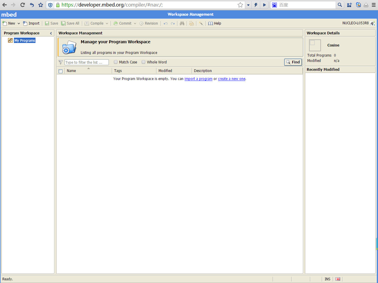
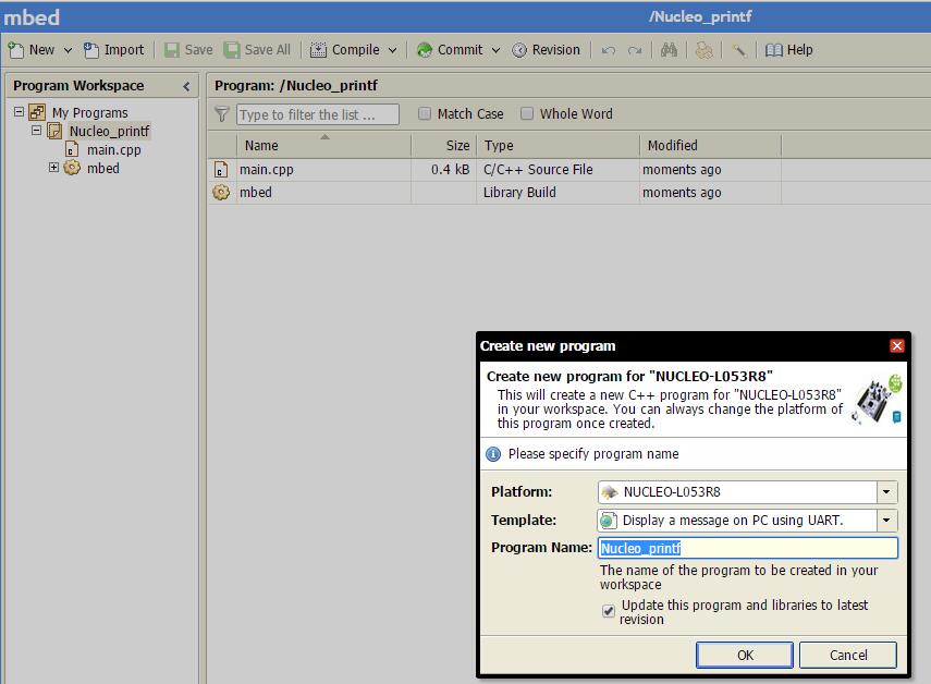
这时可以创建新程序,还有一些模板可以选择

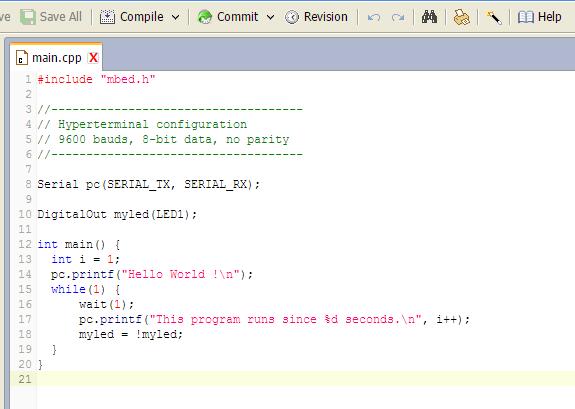
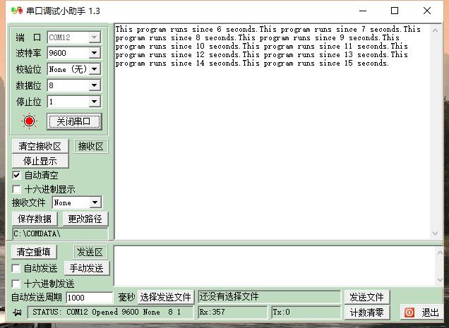
这时点 编译 就能编译出.bin可执行文件,然后下载到 核板 的磁盘就能自动运行

真的很容易上手,感觉和Arduino有异曲同工之妙
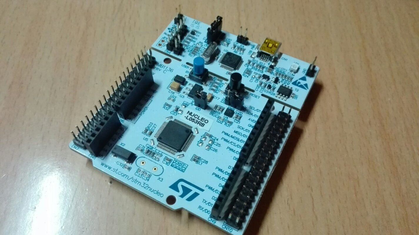

工程师
2016-02-20 11:24:44     打赏
9楼

了解核板

前面提到了Link Debug,这是什么功能呢。

于是我在这里找到了很多核板的参数:

https://developer.mbed.org/platforms/ST-Nucleo-L053R8/


下面是摘抄:


MCU特点
  • STM32L053R8T6 in LQFP64 package
  • ARM®32-bit Cortex®-M0+ CPU
  • 32 MHz max CPU frequency
  • VDD from 1.65 V to 3.6 V
  • 64 KB Flash
  • 8 KB SRAM
  • GPIO (51) with external interrupt capability
  • 12-bit ADC with 16 channels
  • 12-bit DAC with 1 channel
  • RTC
  • Timers (5)
  • I2C (2)
  • USART (3)
  • SPI (2)
  • USB 2.0 full-speed


核板特点

  • Two types of extension resources
    • Arduino Uno Revision 3 connectivity
    • STMicroelectronics Morpho extension pin headers for full access to all STM32 I/Os
  • On-board ST-LINK/V2-1 debugger/programmer with SWD connector
    • Selection-mode switch to use the kit as a standalone ST-LINK/V2-1
  • Flexible board power supply
    • USB VBUS or external source (3.3 V, 5 V, 7 - 12 V)
    • Power management access point
  • User LED (LD2)
  • Two push buttons: USER and RESET
  • USB re-enumeration capability: three different interfaces supported on USB
    • Virtual Com port
    • Mass storage (USB Disk drive) for drag'n'drop programming
    • Debug port


UART 共用到在 D0、 D1 脚

These pins are shared with the PC Serial connection via STLink. If you need to use these pins independently, see this page:https://developer.mbed.org/teams/ST/wiki/Use-of-D0D1-Arduino-pins


引脚使用提示

Only the labels written in blue/white or green/white (i.e. PA_4, PB_5, A0, D14, LED1...) must be used in your code. The other labels are given as information (alternate-functions, power pins, ...). You can also use these additional labels:

SERIAL_TX=PA_2  I2C_SCL=PB_8  SPI_MOSI=PA_7  PWM_OUT=PB_3
SERIAL_RX=PA_3  I2C_SDA=PB_9  SPI_MISO=PA_6
                              SPI_SCK =PA_5
                              SPI_CS  =PB_6


扩展板使用提示

  • (1) - This shield requires SPI pins remapping because it uses a non-standard 6 pin SPI connector. Please refer to the shield page on mbed for more information.
  • (2) - To use this shield with ST Nucleo platforms you will need to remove SB13 and SB14 then bridge SB62 and SB63. This will enable the processor to communicate with the shield using the default serial connection, but will stop the comms going via the ST-Link and USB. Alternatively you could use other serial-enabled pins, which have to be connected to D0/D1 pins on the shield. Please refer to the the Nucleo pinout image for options.
  • (3) - This shield uses I2C on A4/A5 pins and requires bridging of A4D14 and A5D15.
  • (4) - To boot on external power, the PWR jumper (near the reset button) has to be switched to E5V position.


最后,就是 Link Debug 使用驱动和 固件升级


  • Install the ST-LINK/V2 driver before connecting the Nucleo board to your PC the first time. Follow this LINK for all details.
  • For optimum performances, ensure that the Nucleo ST-LINK/V2 firmware is upgraded to the latest version. Follow this LINK for all details.


工程师
2016-02-20 11:26:55     打赏
10楼
至于Mbed的更多功能,就要慢慢探索了,先写到这

共18条 1/2 1 2 跳转至

回复

匿名不能发帖!请先 [ 登陆 注册 ]