
class xxxx {
int cnt;
void fun();
}
然后我想
attachInterrupt(PIN11, fun, CHANGE);
然后在
void fun()
{
cnt++;
}
实现类似这样效果
发现只能绕路实现,直接实现不了的
程序写好了

#define LW_PWM 3
#define LW_IN1 2
#define LW_IN2 4
#define LW_ECA A1
#define LW_ECB A0

#define RW_PWM 5
#define RW_IN1 7
#define RW_IN2 6
#define RW_ECA A3
#define RW_ECB A2

#define CW 0
#define CCW 1

#include "balance_car.hpp"

void setup() {
  Serial.begin(9600);

  BL_CAR.setup_motor(balance_car::LW, LW_PWM, LW_IN1, LW_IN2, LW_ECA, LW_ECB);
  BL_CAR.setup_motor(balance_car::RW, RW_PWM, RW_IN1, RW_IN2, RW_ECA, RW_ECB);
}

void loop() {
  delay(2000);
  BL_CAR.show_pos();
  BL_CAR.run(80, CW, 80, CW);
  delay(2000);
  BL_CAR.show_pos();
  BL_CAR.run(80, CCW, 80, CCW);
  delay(2000);
  BL_CAR.show_pos();
}
调换了一下6,7口,发现接线不对
程序功能为了测试连线和编码器
左右轮顺时针转一会,显示编码器值
再逆时针转一会,显示编码器值
经测试,连线没问题,编码器正常工作
http://playground.arduino.cc/Main/RotaryEncoders
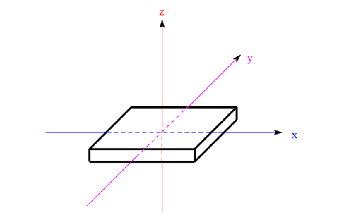
主要理论如下图:

代码参考网站的例子:
/* read a rotary encoder with interrupts
   Encoder hooked up with common to GROUND,
   encoder0PinA to pin 2, encoder0PinB to pin 4 (or pin 3 see below)
   it doesn't matter which encoder pin you use for A or B

   uses Arduino pullups on A & B channel outputs
   turning on the pullups saves having to hook up resistors
   to the A & B channel outputs

*/

#define encoder0PinA  2
#define encoder0PinB  4

volatile unsigned int encoder0Pos = 0;

void setup() {


  pinMode(encoder0PinA, INPUT);
  digitalWrite(encoder0PinA, HIGH);       // turn on pullup resistor
  pinMode(encoder0PinB, INPUT);
  digitalWrite(encoder0PinB, HIGH);       // turn on pullup resistor

  attachInterrupt(0, doEncoder, CHANGE);  // encoder pin on interrupt 0 - pin 2
  Serial.begin (9600);
  Serial.println("start");                // a personal quirk

}

void loop(){
// do some stuff here - the joy of interrupts is that they take care of themselves
}

void doEncoder() {
  /* If pinA and pinB are both high or both low, it is spinning
   * forward. If they're different, it's going backward.
   *
   * For more information on speeding up this process, see
   * [Reference/PortManipulation], specifically the PIND register.
   */
  if (digitalRead(encoder0PinA) == digitalRead(encoder0PinB)) {
    encoder0Pos++;
  } else {
    encoder0Pos--;
  }

  Serial.println (encoder0Pos, DEC);
}
偷偷告诉你,例子有bug,你能发现不?
读取CurieIMU的加速度计和陀螺仪数据
参考API:
https://www.arduino.cc/en/Reference/CurieIMUreadMotionSensor
Description
Reads the raw values of the motion sensor (accelerometer + gyro).
SyntaxCurieImu.readMotionSensor(int ax, int ay, int az, int gx, int gy, int gz)
Parameters
ax: a variable in which the accelerometer's value along x will be stored.
ay: a variable in which the accelerometer's value along y will be stored.
az: a variable in which the accelerometer's value along z will be stored.
gx: a variable in which the gyro's value along x will be stored.
gy: a variable in which the gyro's value along y will be stored.
gz: a variable in which the gyro's value along z will be stored.
以上数据为原始数据。
转换方法:
To convert the raw value into mg use the following formula:
float g = (gRaw/32768.0)*getAccelerometerRange()
where gRaw is either ax, ay or az.
来自:https://www.arduino.cc/en/Reference/CurieIMUreadAccelerometer
To convert any of the raw values in angular velocity (°/s) use the following formula:
float av = ( avRaw/32768.9)*getGyroRange()
where avRaw is either gx, gy or gz.
来自:https://www.arduino.cc/en/Reference/CurieIMUreadGyro
有关自动校正:
https://www.arduino.cc/en/Reference/CurieIMUautoCalibrateAccelerometerOffset
https://www.arduino.cc/en/Reference/CurieIMUreadGyro
float conv_g(int gRaw) {
  // 转换成标准重力加速度
  return (gRaw/32768.0)*CurieIMU.getAccelerometerRange() ;
}

float conv_av (int avRaw) {
  return (avRaw/32768.0)*CurieIMU.getAccelerometerRange() ;
}

void balance_car::showIMU()
{
   readIMU();
   char buf[100];
   sprintf(buf, "IMU data: %d, %d, %d, %d, %d, %d", _ax, _ay, _az, _gx, _gy, _gz);
   Serial.println(buf);

   sprintf(buf, "IMU data: %f, %f, %f, %f, %f, %f", conv_g(_ax), conv_g(_ay), conv_g(_az), conv_av(_gx), conv_av(_gy), conv_av(_gz));
   Serial.println(buf);
}
部分测试代码如上:
小车直立放置后,输出结果如下:
LW:0 RW:0
LW:0 RW:0
IMU data: 4, -25, 16301, -15, -4, -10
IMU data: 0.000244, -0.001526, 0.994934, -0.000916, -0.000244, -0.000610
LW:0 RW:0
LW:0 RW:0
LW:0 RW:0
IMU data: -4, 17, 16296, -4, -7, 7
IMU data: -0.000244, 0.001038, 0.994629, -0.000244, -0.000427, 0.000427
LW:0 RW:0
LW:0 RW:0
LW:0 RW:0
IMU data: 34, -8, 16347, -6, 0, 0
IMU data: 0.002075, -0.000488, 0.997742, -0.000366, 0.000000, 0.000000
模仿别人写了个角度计算的函数
float balance_car::Angle_Calcu(void)
{
    readIMU();
    float angleA= atan(conv_g(_ay)/ conv_g(_az))* (180)/ 3.1415926;
    return angleA;
}
然后loop中输出角度
这个角度基本上准确
用串口绘图软件看,虽然角度基本正确,但是运动的时候,图像有锯齿
网上说要滤波,回头研究一下咋滤波呢
 我要赚赏金打赏帖 我要赚赏金打赏帖 |
|
|---|---|
| 片外存储Flash使用方法(Arduino IDE环境)被打赏¥22元 | |
| 三分钟快速上手ESP-NOW(ArduinoIDE环境)被打赏¥23元 | |
| 【S32K3XX】LPSPI参数配置说明被打赏¥21元 | |
| 在WT9932C61-TINY上实现超声波测距被打赏¥22元 | |
| 基于WT9932C61-TINY的环境构建及OLED屏驱动测试被打赏¥20元 | |
| 【S32K3XX】Core-to-Core 中断使用被打赏¥21元 | |
| 「AI编程记录--含源码」用一晚上的时间写一个esp32的示波器被打赏¥19元 | |
| STM32C0116DK开发探索记(3)被打赏¥30元 | |
| STM32C0116DK开发探索记(2)被打赏¥24元 | |
| STM32C0116DK开发探索记(1)被打赏¥29元 | |

 STM32
STM32 MCU
MCU 通讯及无线技术
 物联网技术
物联网技术 电子DIY
电子DIY 板卡试用
板卡试用 基础知识
基础知识 软件与操作系统
 我爱生活
我爱生活 小e食堂
小e食堂

